Jump to content
 
  • entries
    172
  • comments
    1,473
  • views
    376,511

Round and Round, and Up and Down – the pictures


Silver Sidelines

2,096 views

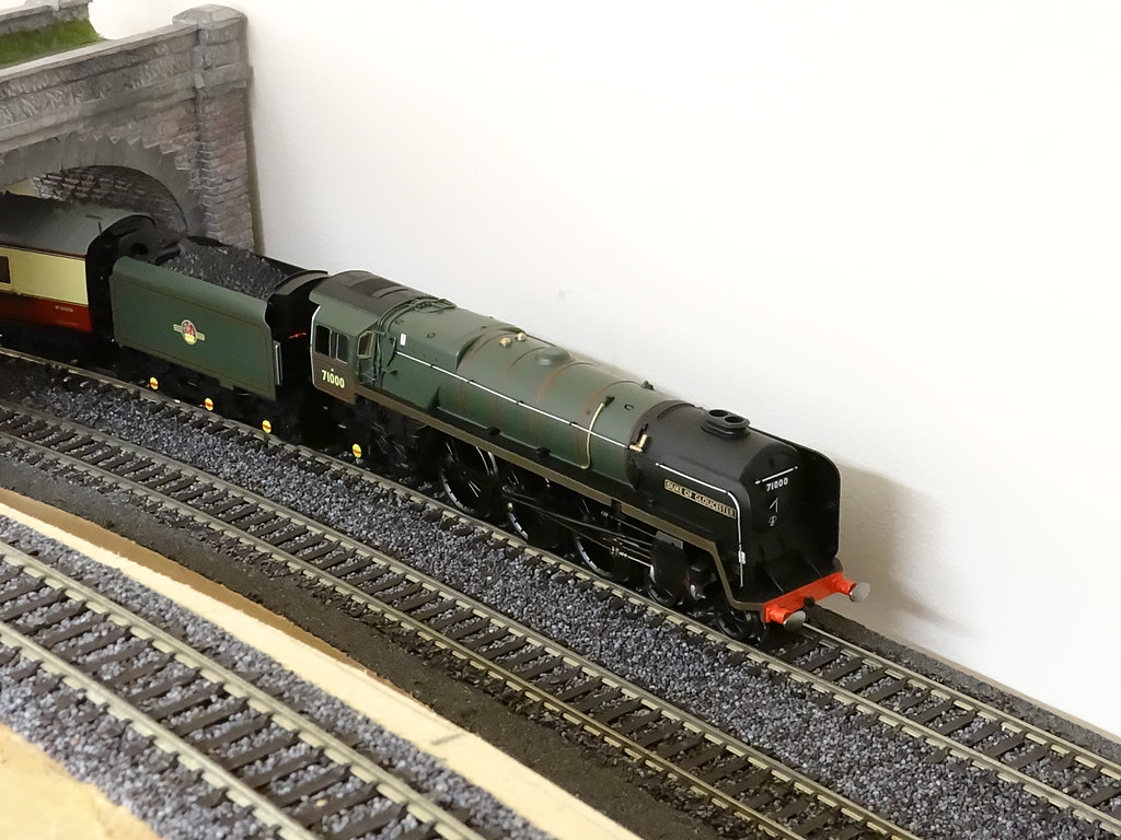
This Post is a direct follow up to my previous post and provides some illustrations of the mid level ‘round and round’ (the continuous run), and the low level reversing loop. The pictures also feature Hornby R3191 which has recently taken up a lot of my time. It is getting to be quite an expensive engine – well if I had to charge for the time I have spent fettling it.

13042180625_733c5b2bd3_b.jpg

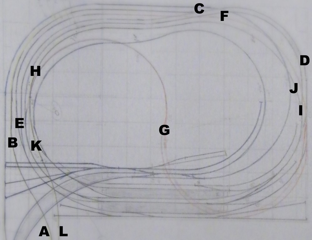
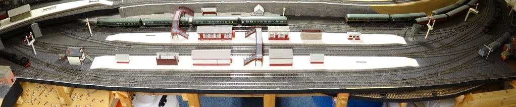
The Grand Plan – with photo locations

As planned and initially constructed the layout was to be ‘Out and Back’ with a Main Terminus, a double track mainline leading to ‘the Main Junction’ and then heading off to a return loop with storage sidings.

I have annotated the track plan above to show where the pictures were taken. The locations are labelled A to L in exactly the order that trains travel around the layout.

13040936763_9288d02d3d_b.jpg

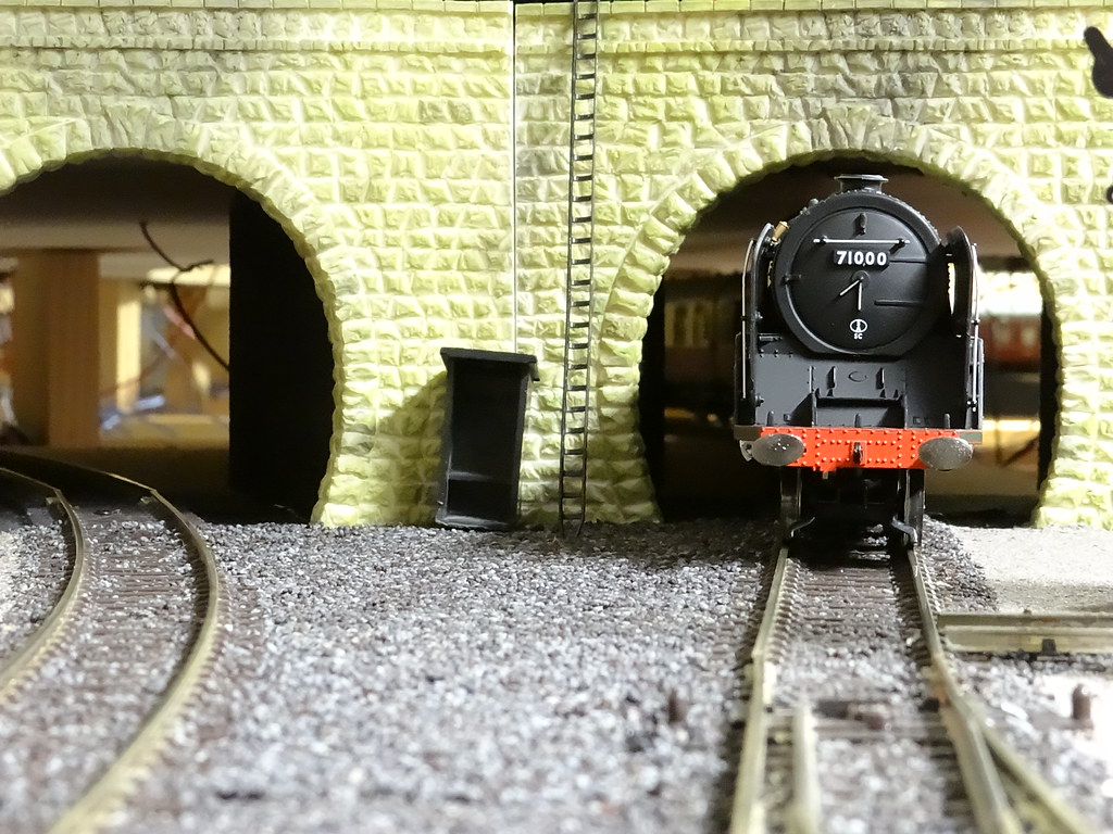
Location A Starting out – the double track main line from the Terminus Station

The double track main line from the Terminus Station starts out at the lowest level. This allows the ‘double track’ to pass beneath the Main Junction Station (and the Branch Junction Station at the higher level above).

13040758005_da9e849347_b.jpg

Location B – Starting the climb to the mid level

Passing beneath the Main Junction Station the double track splits into ‘up’ and ‘down’ lines that rise up to the mid level ‘round and round’ track. To try and make life easier for climbing trains, the ‘up’ line has a shallower gradient than the ‘down’ line.

13040725955_a35747369e_b.jpg

Location C – the ‘up’ Main Line from the Low Level joining the ‘round and round’

The ‘round and round’ was installed so that I could simply sit and watch trains go by. I would say that it is almost essential to have a continuous run for test purposes.

13041056634_a2d2ca1d80_b.jpg

Location D – the ‘round and round’ (continuous run) approaching the Main Junction

At the planning stage the arrangements for the reversing loop were deemed to be behind the scenes and hence would not be ballasted. However as the layout has progressed it is apparent that some locations are suitable to be scenically developed and some ballasting has crept in.

10563008215_1095d5edac_b.jpg

A reminder - the Main Junction

The ‘round and round’ from the Main Junction passes beneath the high level Branch Junction.

13040662055_ab9b6d3212_b.jpg

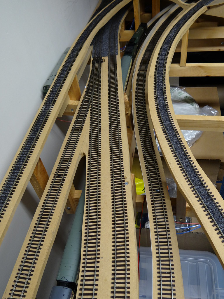
Location E – leaving the ‘round and round’ to start the descent to the low level Reversing Loop

After passing under the Branch Junction there are the two connections to the Reversing Loop, one down and one back up.

13040762453_e3f241f881_b.jpg

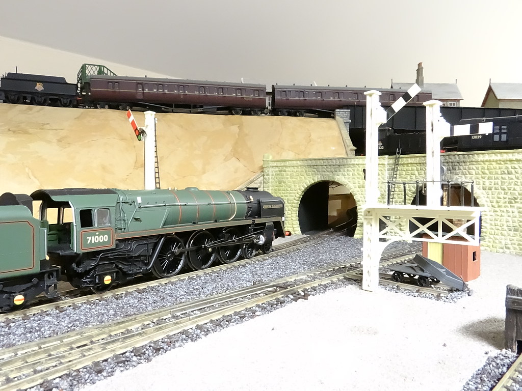
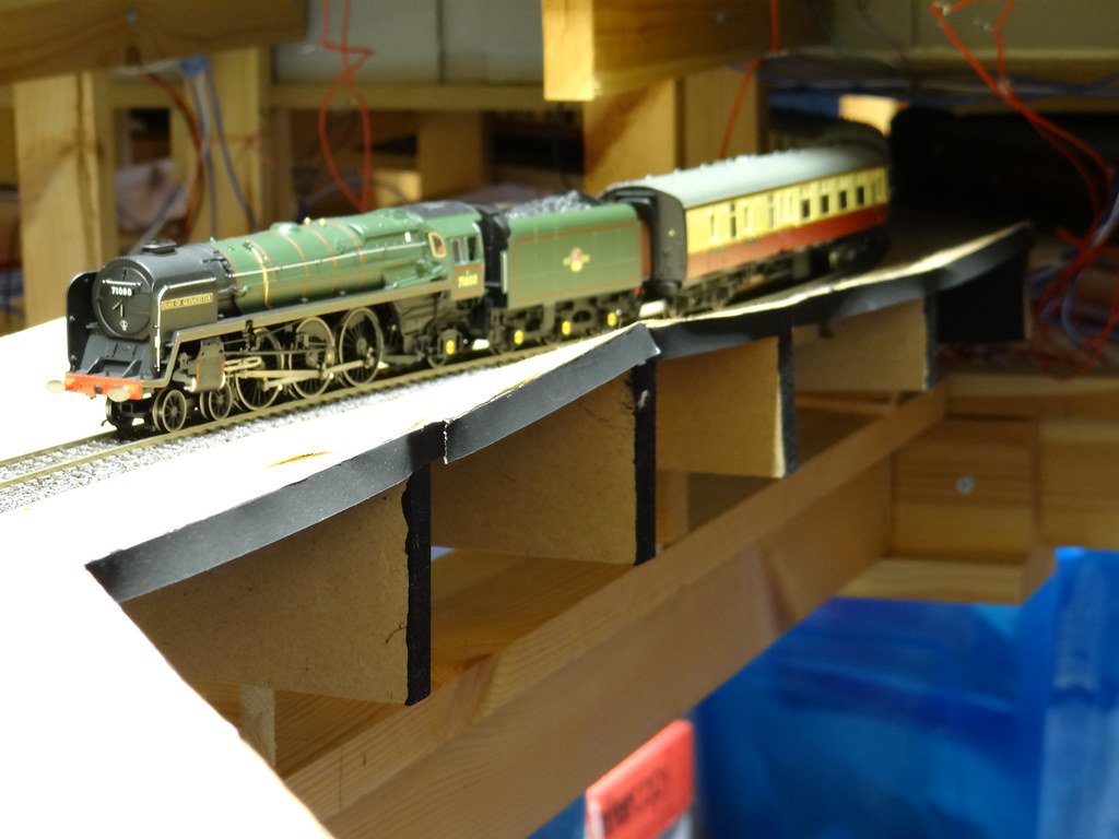
Location F –the low level Reversing Loop passing beneath the ‘round and round, note the Connecting Line at the extreme right ’

Trains travelling down from the ‘round and round’ on the low level reversing loop always travel in the same direction and hence the descent can be made relatively steeply, enabling the descending tack to pass beneath the ‘round and round’ (continuous run).

13040560235_d9bb9875a1_b.jpg

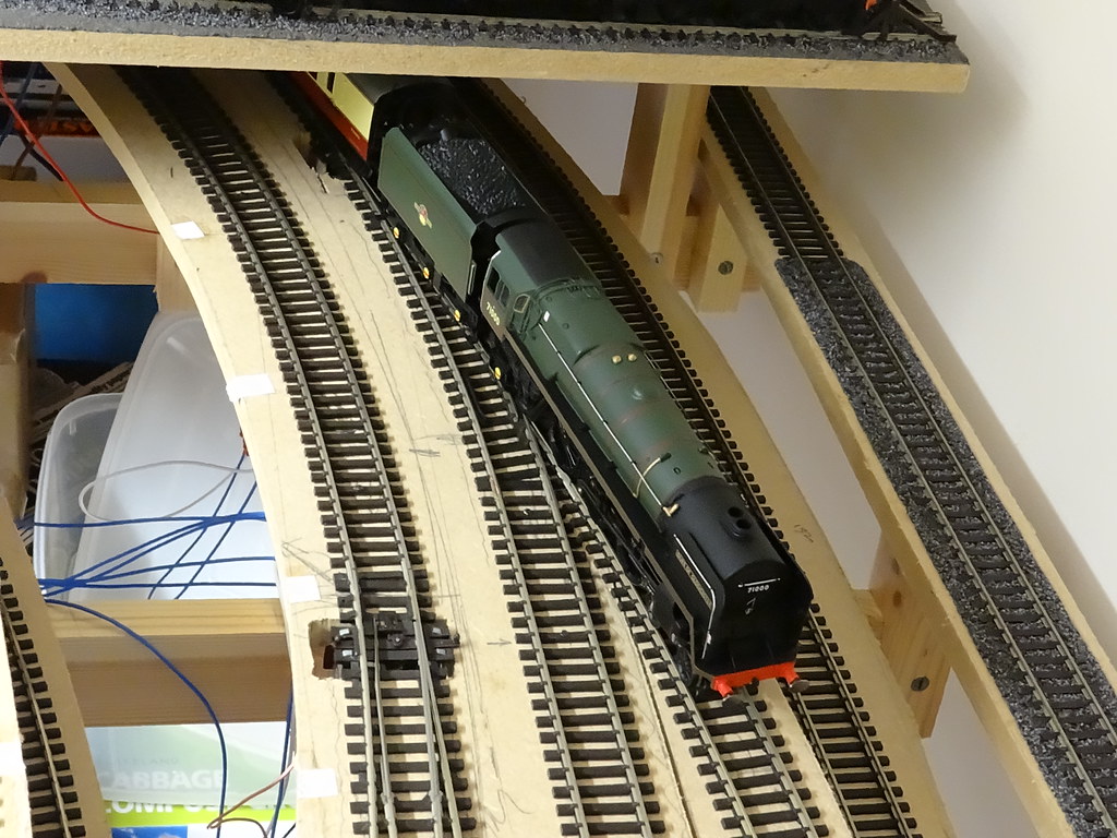
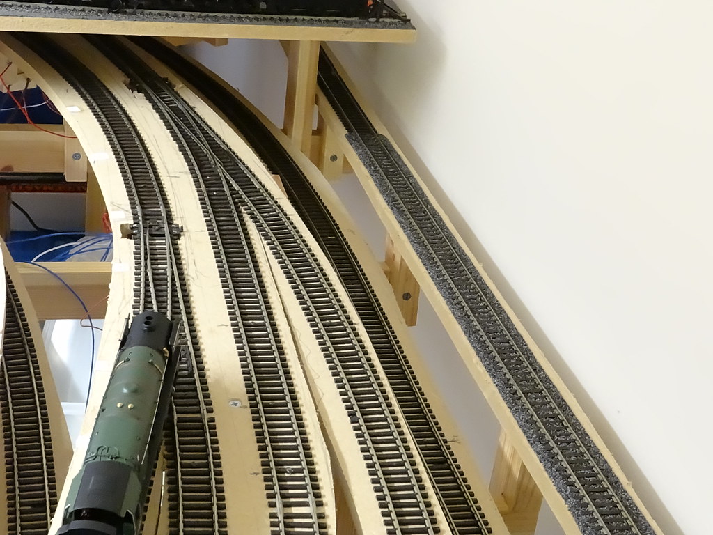
Location G –emerging from the low level reversing loop

The climb back up from the reversing loop is the most severe on the layout. As well as being on a 3ft radius curve there is the added complication that the track has to pass beneath the Connecting Line from the Main Junction up to the Branch Junction (the ex LNWR line) visible at Location F above. In theory the line would be 1 in 60 but I think the reality is that it is nearer 1 in 56.

13040525575_cbabbc31ac_b.jpg

Location H –rejoining the ‘round and round’ from the reversing loop

After exiting the Reversing Loop trains pass back under the Branch Junction and emerge again at the Main Junction.

13040854004_b242ce85f4_b.jpg

Location I –exiting the ‘round and round’

The turnout from the continuous run back down to the double track Main Line is hidden visually from the front of the layout by a signal box. The location close to the Main Junction station was dictated by the requirement to use 3ft radius curves.


13040826674_6f261b15ac_b.jpg

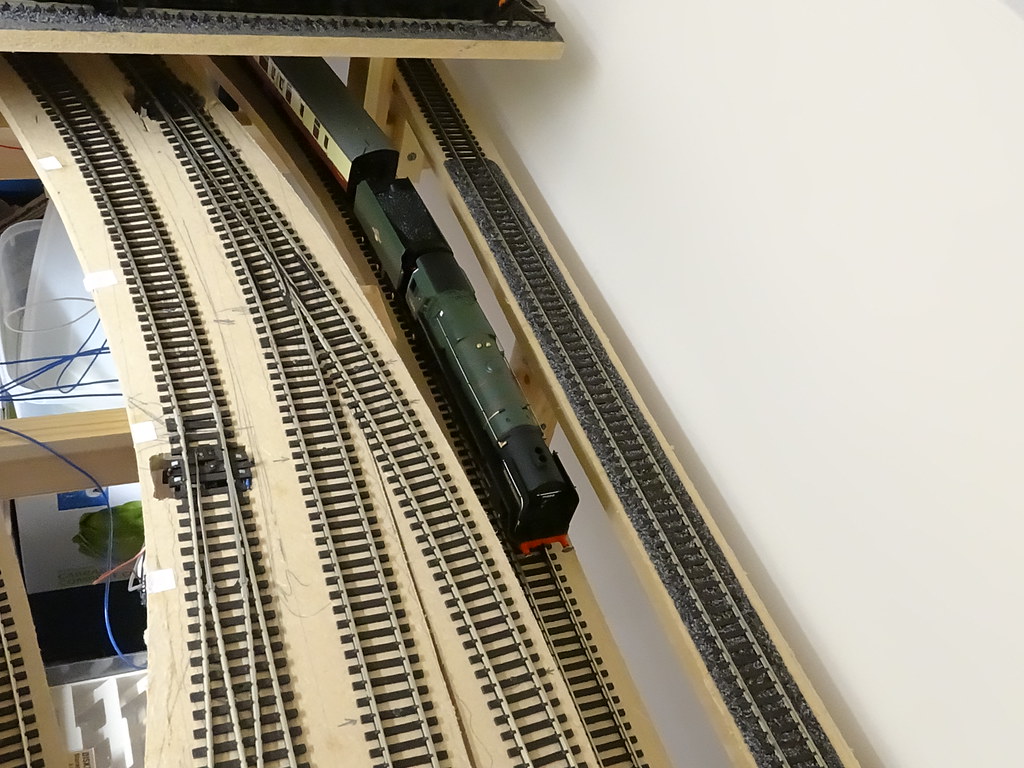
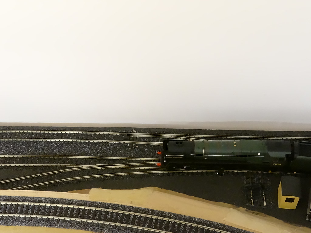
Location J–starting the descent to the low level double track Main Line – note the low level reversing loop at the bottom of the picture


13040433925_75c0a70da0_b.jpg

Location K –back to the low level

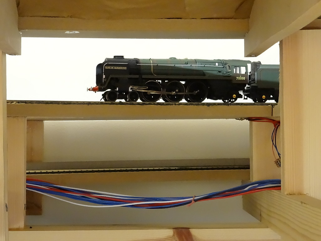
Finally a view of the ‘down’ line with a train emerging from beneath the Main Junction on the double track Main Line.

13040536023_6bc8de99fd_b.jpg

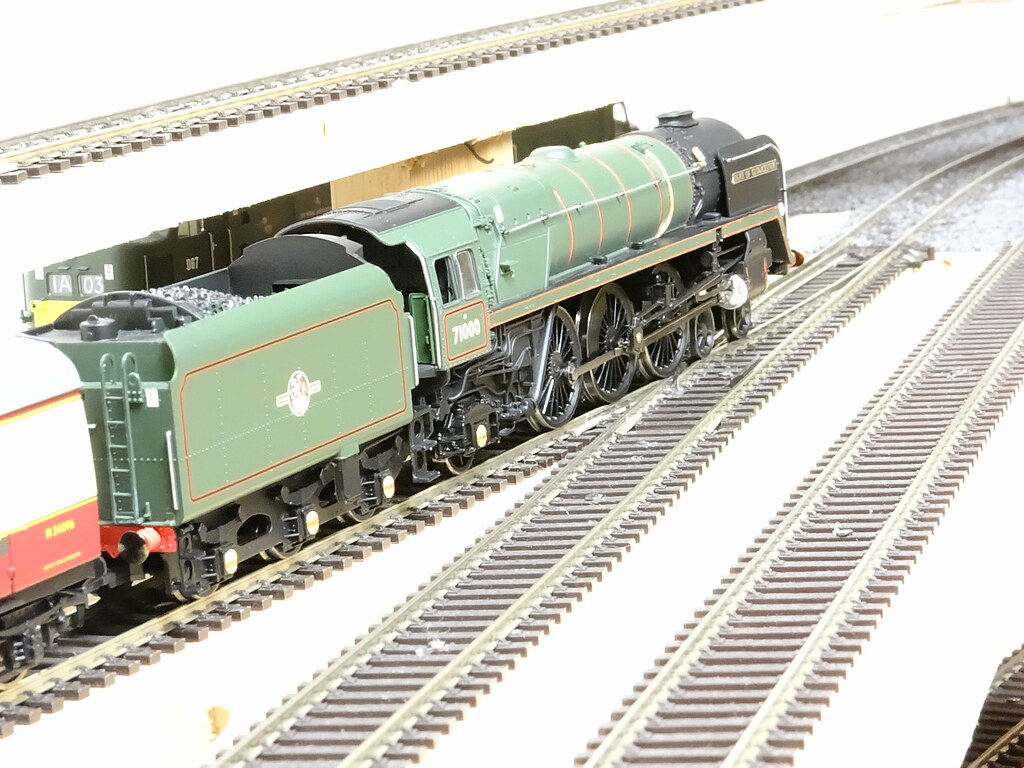
Location L –returning home

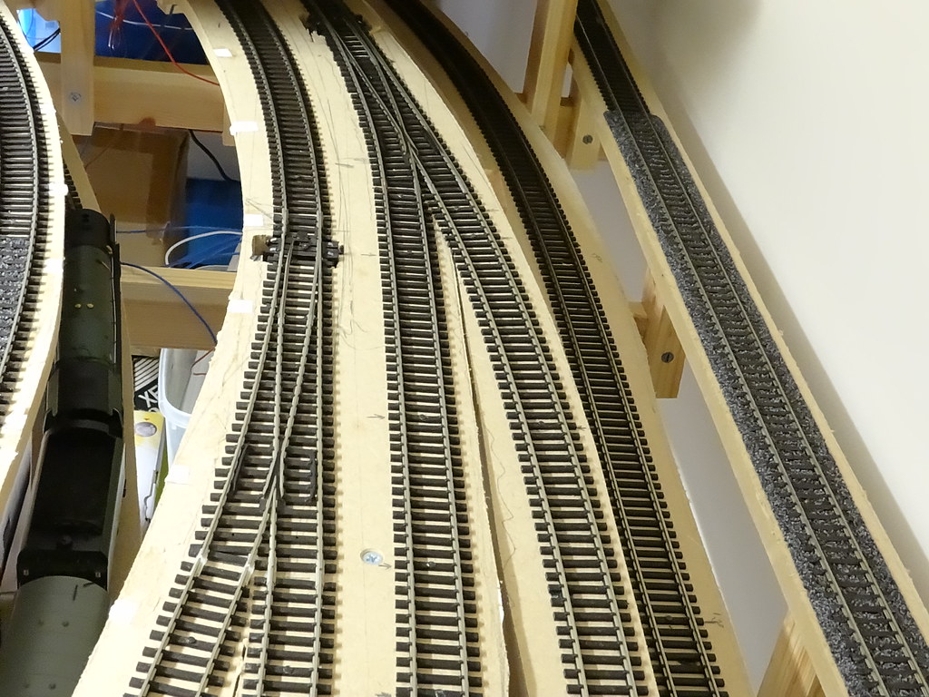
Close up pictures are really quite unnerving. After viewing the above picture I had to inspect the rail joint at the toe of the point on the left. Visually all appears satisfactory although looking at the picture I suspect that the gauge has spread at the toe of the Peco large radius point.

After the pictures there is

. As you will see I need to practice holding the camera steady!
  • Like 6

11 Comments


Recommended Comments

Hi there,

I've been looking with interest at your various topics and thoroughly enjoying the progress.

Having got to that stage of finally ? planning my own layout and watched other excellent videos of "roundy roundy" types I have decided to keep it on the level.

I notice with a reasonably long train there are the inherent problems with wheel spin on an incline ( using 4-4-0's especially ) and without the room to get a decent run at an scale incline, and also considered using the DCC Systems magnetic solution. May I ask, do you find many problems with yours when pulling a decent length train.

Keep up the good work and happy modelling.

Link to comment

Thank you for the interest.  This is the third proper layout that I have constructed - you learn a little bit more each time.  The gradients are about 1 in 60 and the curves are minimum 3ft radius.  From my experience this track combination allows me to run seven coach trains.  Hornby Britannias (and  DoG), Bachmann Evening Star, and most Bachmann and Heljan Diesels are well capable of hauling such trains.  Other models of express engine such as Hornby Castles, Cities, Princesses, and Bachmann A1s, and A4s will probably need the addition of some extra lead ballast.  My layout is not digital, I use Gaugemaster Inertia controllers.  This means that I can utilise the space for the Digital Control Chip for adding lead. I really do not see the need for digital control but then that might just show my age.


Speak again


Regards


Ray

Link to comment

Hi Ray,

Sorry you had to explain all again ( I read your reply on the YouTube vid to another interested modeller re: gradients ).

During my "experiments" I have made a simple helix, which actually doesn't go anywhere! , however it was useful for the purposes of testing loco' s whether they be steam or diesel on the min. 3 ft radius, and true to form the diesels would usually outperform ( no real surprises there then!).

I do use dcc however, I was referring to the DCC Concepts Powerbase system which uses magnets attached to the base of a loco being pulled ( if that's the right explanation) up an incline. Search Installing DCC Concepts Powerbase on the inter web and it makes for an interesting watch.

No, I don't think it's an age thing, just what we are happiest with and enjoy.


Kind regards


Grahame

Link to comment

Ray


What a brilliant video, certainly a layout to be proud of, one question though, are you softening towards the DoG???

Link to comment

Good Morning Paul

.. are you softening towards the DoG???

Yes - it has a good 'shape'.  My example was not put together correctly and simple things like the shape of handrails can make or mar a model.  Paying Hornby a significant premium for the Special Edition with plastic 'etched plates' was not a good idea!


Regards


Ray 

Link to comment

Hi bgman

. Search Installing DCC Concepts Powerbase on the inter web and it makes for an interesting watch. ..

I will go and look, thanks, Ray

Link to comment

Hello again

.. the DCC Concepts Powerbase system which uses magnets attached to the base of a loco being pulled ..

You are right, there is a lot written on RMweb and similar places about steel plates and magnets.  Tri-ang Magnadesion comes to mind.  If I read the reports correctly the smaller the gap between the magnets on the engines, and the plates beneath the rails, the better the performance.  For 00 gauge, engines with small diameter wheels running on Code 75 rail would appear to benefit more than engines sat up high running on Code 100 rail.   I guess sticking magnets beneath engines is no more fiddly than packing the body with lead - but together with the steel plates might be more costly.  I shall await to hear more.


Regards


Ray

Link to comment

Graham, Sorted

..re: gradients ...

You need a 'banker' -
of even the ex LMS 4-4-0 on the local train needing the help of a Jinty to get it up the 1 in 37 gradient.


In fact in the early days before I had added any lead I used to send a banking engine back down the reversing loop to 'double head' back up. The 'banking' engines were stored in the siding at the end of the platform between the up and down roads.  A major disadvantage was the need for the train engine to have a front coupling.

10885124754_4068fd351c_b.jpg

Link to comment

Glad to see you follow '' the old ways" i'm certain others may agree, well done. 

Link to comment

Create an account or sign in to comment

You need to be a member in order to leave a comment

Create an account

Sign up for a new account in our community. It's easy!

Register a new account

Sign in

Already have an account? Sign in here.

Sign In Now
×
×
  • Create New...