

Mind the Gap
.thumb.jpg.60c53fcbcaa34017b05b8919d1a9e6d2.jpg)
Entry posted by Silver Sidelines
3,098 views
A change of scenery, well a change from running trains. There has been a gap between the two baseboards ever since the layout was started and it was time to block up the opening:
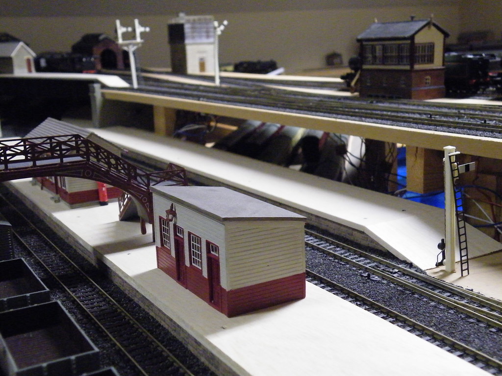
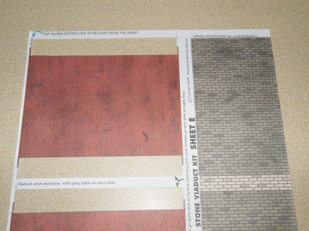
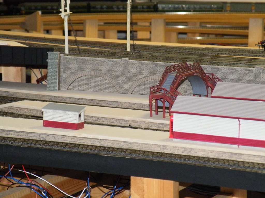
I wanted an arched retaining wall. Time and economy are important and I favour the use of card kits. In this instance I decided to make the wall using parts from the Metcalfe Two track Viaduct Kit (PO241).
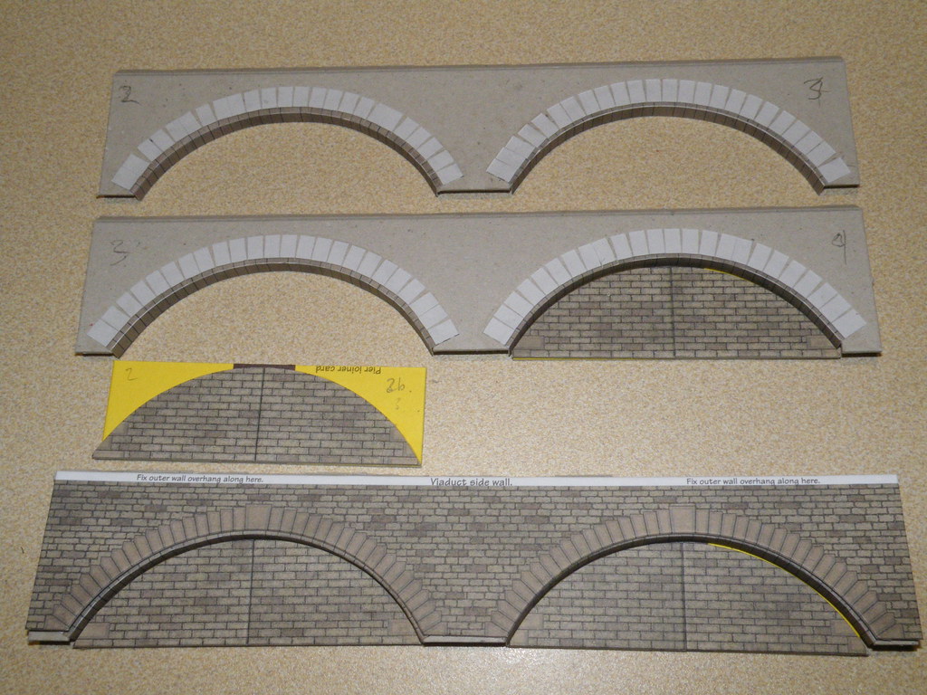
The first task was to form the arches. The picture above shows how parts of the internal viaduct supports from the kit were used to shape and form the internal arch walls. The underside of the arch ring being cut from the 'brick' paper provided with the kit.
More by good luck, than by design, I found that the height between my platform and the underside of the upper baseboard was almost exactly the height of the top part of the arches from the kit. Time then for a dry run:
Once I had established that everything was going to fit the arch parts of the walls were glued top and bottom and pushed in place between the upper board and the platform. It was then a relatively quick job to stick the facings to the arches and to glue the top brick wall in place. The 'devil' was then in the detail.
Metcalfe recommend 'impact' adhesive. I find such glue messy and instead use PVA.
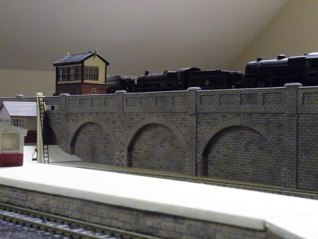
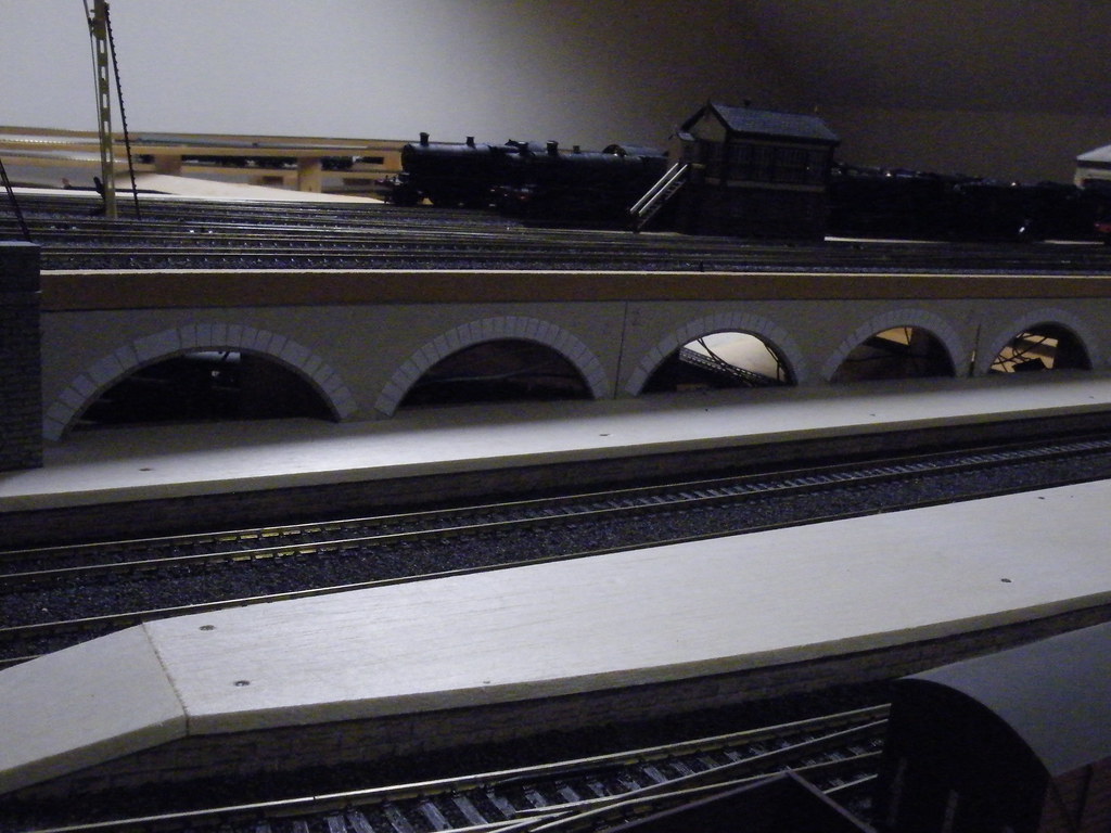
At the end of the platform the arches had to be carried down to the top of the lower baseboard. I also needed to fabricate a 'third' arch. The Metcalfe kit assumes that the arches will be made up two at a time. The length of wall needed here meant that I would have to make a single arch. I must have been losing concentration because it took three attempts to get the heights of adjacent arches to match each other whilst at the same time remaining vertical. (I am sure you will be familiar with the situation where baseboards are not quite as level as first imagined.) Finally this end of the wall was finished with a shorter plain section of wall with a triangular tapered section to connect up to the approach embankment.
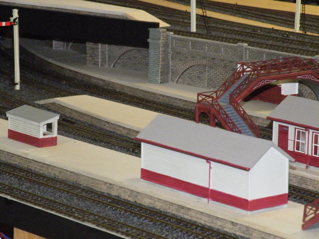
There was then the small matter of what to do under the girder bridge at the opposite end. Waste not want not. I was able to reuse the two arches previously discarded for being the wrong height. These were glued in place, beneath the bridge, around a dummy pillar to give some semblance of support for the overlying bridge structure.
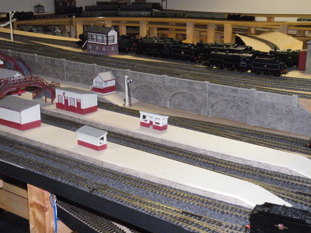
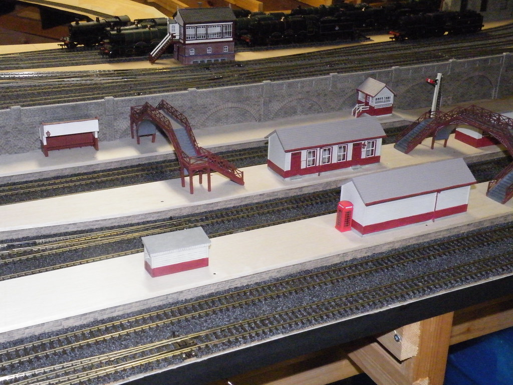
Finally a general shot of the finished wall.
-
 5
5

4 Comments
Recommended Comments
Create an account or sign in to comment
You need to be a member in order to leave a comment
Create an account
Sign up for a new account in our community. It's easy!
Register a new accountSign in
Already have an account? Sign in here.
Sign In Now