

A Cheap and Cheerful Turntable
.thumb.jpg.60c53fcbcaa34017b05b8919d1a9e6d2.jpg)
Entry posted by Silver Sidelines
11,825 views
A model railway friend has recently upgraded and motorised his kit built turntable. He has used parts formed with a 3D Printer - real cutting edge technology. As a result I have been shamed into refurbishing my hand operated turntable made in the 1980s.
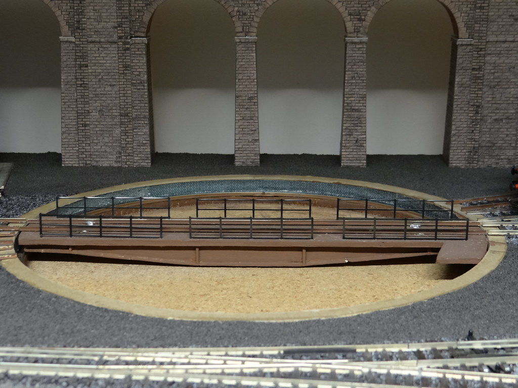
Turntable prior to refurbishment
In the 1980s there was the Airfix turntable, now marketed by Dapol. This was a plastic kit for an above ground turntable. At the time I thought it a disappointment as it was particularly flimsy and I could not figure out how to make it into a working model. Having discarded the Airfix model, what next? Well there was the Hornby / Triang turntable with its X04 Triang motor. It perhaps lost marks for lack of detail but it did work. Well it moved in fits and starts – and made lots of noise, something my now married daughter is still keen to remind me about! As a child she was lucky enough to have the bedroom right next to the railway room.
I would build my own turntable – with a proper well. It was assembled in the days before digital cameras so we will have to make do with pictures of the finished product.
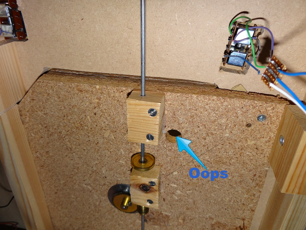
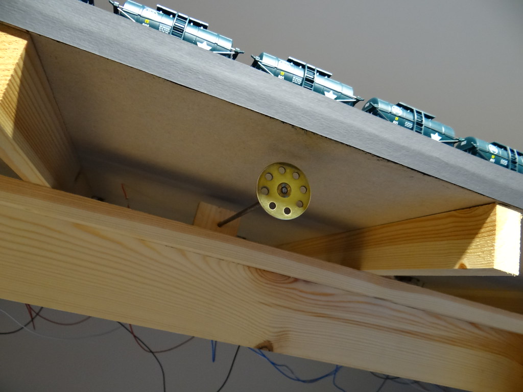
A view of the turntable unit from below
The turntable unit was assembled from three identically sized pieces of 1/2 inch board which would be slotted into the existing baseboard structure. The base of the turntable was chipboard. Above this were two pieces of 1/2 inch plywood which had a circular hole cut into them to form the walls of the well. The holes were cut with a jigsaw and I would have started the cutting by drilling a 1/2 inch hole with a ‘zip’ drill. I tend to rush at jobs and it has been evident for a number of years that I had drilled the initial 1/2 inch starter hole through all three pieces of board – including the base!
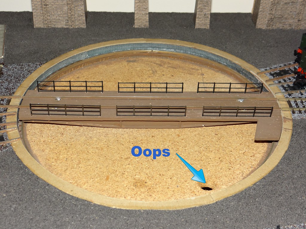
A mistake during construction 30 years ago
The hole in the middle piece of plywood was made a smaller diameter to form a step on which to carry the circular track for the turntable deck to run on.
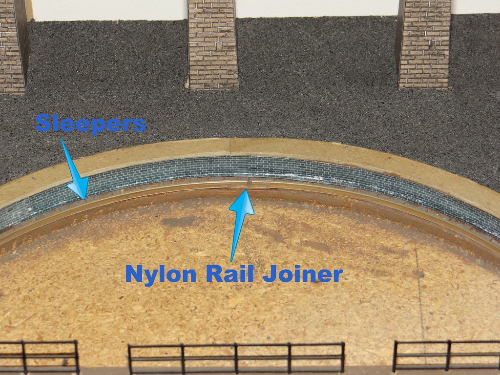
Close up of turntable track
The circular track inside the turntable well was formed from something flexible like Code 75 Bullhead Rail and is used to provide current to the tracks on the rotating deck. Short lengths of cardboard sleeper were glued around the outside of the turntable well to assist in positioning the circle of nickel silver rail. The circle of track was made in two sections fastened with nylon rail joiners – to provide the necessary change in polarity when rotating the deck.
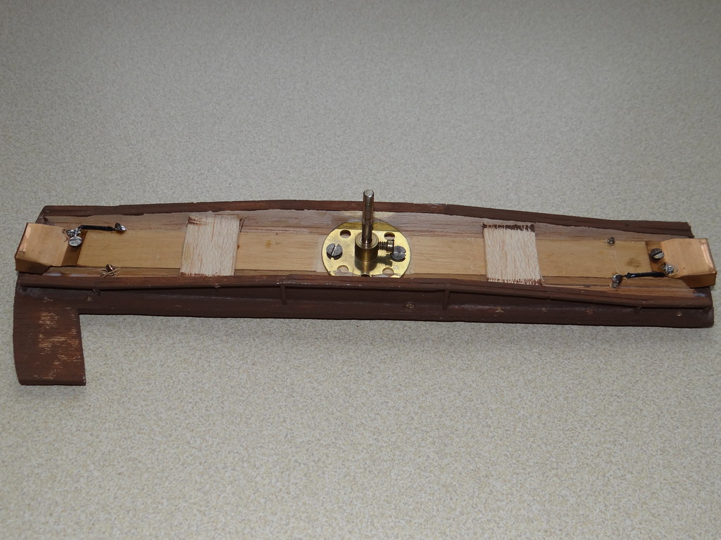
Underside of Deck
The dimensions of the turntable deck have a close similarity to the Airfix model – including the provision of a platform at one end for the dummy hand operating gear. I used 1/4 inch plywood for the top of the deck which was then reinforced underneath with a 1/4 inch strip of hardwood. The dummy side girders were constructed with 1/8 inch balsa wood, the over wide spacing being necessary to enclose the brass wheel from Meccano used to connect to the mechanism below. The ends of the deck were each carried on pieces of bent brass, or was it copper sheet, as manufactured in the 1960s as draft excluder for fitting round doors and windows. As well as providing support the copper sheet provided an electrical connection between the circular rails in the well and the rails on the deck.
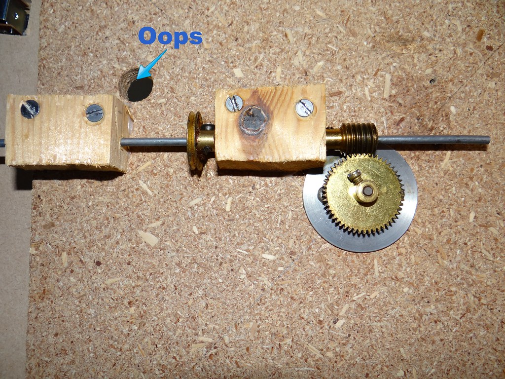
The Mechanism
The mechanism started life as pure Meccano. I forget why but the brass wheel for the centre pivot was replaced a long time ago with a purpose made ‘bush’ turned by a colleague at work. I have in my mind that the orginal Meccano item had too much play in it and that in the 1980s it was difficult to source a replacement item.
The Hand Wheel
The turntable is operated by a hand wheel under the edge of the baseboard – ideally this should have been made more ‘hand friendly’.
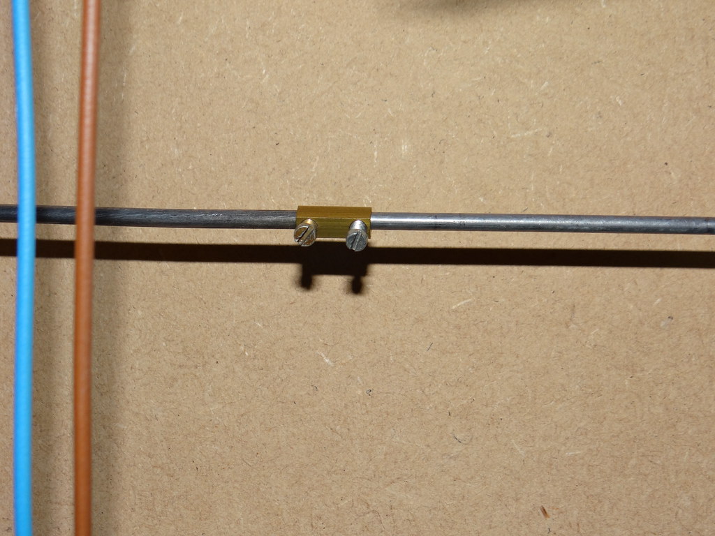
The Joiner
For the first location for the turntable on the Park View Layout the drive rod to the edge of the baseboard was formed from the remains of a wire coat hanger. In the turntable’s most recent location the drive has had to be extended. This was achieved using a length of suitable diameter welding rod and joined with a brass connector taken from inside an electrical ‘chocolate block’ type fitting.
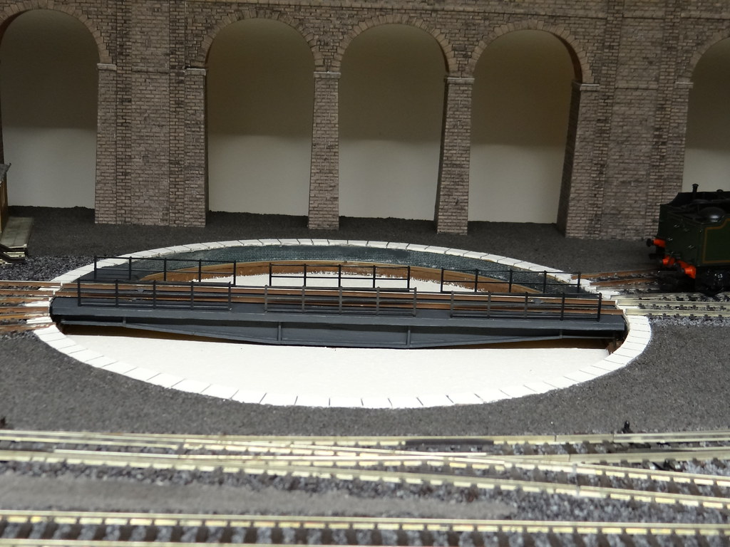
Refurbished
Finally a view of the refurbished turntable. The sections of handrail were left over from my first Hornby turntable. The ‘magnolia’ paint used for the stone edging and the concrete base is obviously over bright and will need some suitable weathering!
-
 1
1

4 Comments
Recommended Comments
Create an account or sign in to comment
You need to be a member in order to leave a comment
Create an account
Sign up for a new account in our community. It's easy!
Register a new accountSign in
Already have an account? Sign in here.
Sign In Now