

Entry posted by SouthernRegionSteam
638 views
 I'm really sorry for the title... OK, maybe not that sorry!
Welcome to the blog outlining my plans for a new layout based off of the old AGWI refinery railway(s) of Fawley.
If you are a member of NGRM-online, there is also a thread for this layout there, or alternatively I have my external blog here if you so fancy!
Hello! You may or may not have seen my old layout "Calshot". Well this project is the follow up to Calshot, and I hope it will give me my much needed modelling mojo back! I decided to settle on the NG lines at Fawley oil refinery based off of my diorama I created for the 2011 RMweb challenge. I really enjoyed building that, and so I thought it would be a good place to start. This layout will also have some interesting and rarely modelled features to boot - such as the aerial ropeway and conveyor belt. All which explain my reasons for deciding to try and model part of this interesting site. Once again, I have decided to base my layout off of a real location, let's hope it pays off again!
(Scroll all the way down if you just want to see my initial 3D sketch and plan!)
Brief History
- Permission granted for a refinery to be built at Fawley on marshland.
- Construction commenced on 10th August, 1920 using temporary railway tracks.
- October, 1920 - Ashlett Creek (directly south) repaired by local council for refinery use.
- 5 ton standard gauge travelling steam crane installed on the creek quay to un/load materials.
- 2 foot gauge line built from the quay to the refinery site to haul construction materials.
- Asphalt plant built 1923 (cost £24 000). Produced a lot of railway traffic - 150 tons daily.
- AGWI Jetty built in the late 1920s for Asphalt and oil traffic. Ashlett Creek used less.
- Decline in use of the narrow gauge railway from 1937 as locomotives slowly sold off.
- The 1939-1945 war mostly shut down the refinery. One train on duty for fire-fighting.
- Narrow gauge railway rarely used up until 1957 where one loco remained to help demolition.
- H17 - last engine, stayed to help partially demolish the old jetty, sold in '61 for preservation.
- Huge expansion of the refinery between '50 and '51 carried out by road vehicles.
Early Days of the Railway
- Line operated at first by a Decauville 0-4-0 loco and 23 tipper wagons.
- Materials such as piling, steel sheets (for the storage tanks), pipes, and gravel.
- Filling of bulk materials onto railway wagons was done by hauling wagons onto the barge with the steam crane, loading them, and lifting them back onto the other track (there were 2 sidings on the quay).
- Trains were propelled on the way to the quay and hauled on the way back as there was no run-around loop at Ashlett Creek.
Traffic
Asphalt was the main traffic for the narrow gauge railway. Drums were taken from the storage/filling area either by railway or the aerial ropeway to the intermediate storage area. I believe this was a raised platform a new hundred meters from the end of the jetty, located where an angle station was for the aerial ropeway. This meant barrels could be stored on this platform until a vessel docked at the jetty. The drums were again either taken by the aerial ropeway or by rail. Two trains were usually used for this task - having to pass on the two sidings at the ABH (Asphalt Bag House??).
Other traffic included (but not limited to):
- Coke from vessels at Ashlett Creek to Coke Retorts (until around 1922/23)
- Other materials such as ballast from Ashlett Creek
- Asphalt in drums or otherwise to vessels at Ashlett Creek
- Acid Tar from the Continuous Naptha Treating Plant to the jetty (in 2x small tank wagons)
- Fire fighting trains (3-4 flat cars with equipment) stationed at strategic points
- Items to and from the workshops
- People (on a 4 wheeled wagon with 2 park benches back to back) from the workshops to jetty
- Rigging equipment, stores, pipework, plates and tanks
- Refuse to the drum area, earth, and grass cuttings
Locomotive Timeline
-
1922 - The only steam engines; Wren 0-4-0T and Decauville 0-4-0T No. 123 arrived
-
1922 - Motor Rail 40HP loco arrived (Named "Greenfly" by staff)
-
1926 - Second 40HP Motor Rail arrived (Original WDLR number 2184 kept)
-
1927 - Both remaining steam locos sold off.
-
1927 - 4x Motor Rail 20HP locos arrived (Given AGWI nos. H.5, H.6, H.7, H.13)
-
1928 - 4x Motor Rail 20HP locos arrived (Given AGWI nos. H.10, H.11, H.12, H.14)
-
1937 - Motor Rail 20HP loco arrived (Given AGWI no. H.15)
-
1937 - Locomotive numbers H.5, H.6 & H.7 written off.
-
1938 - Motor Rail 20HP loco arrived (Given AGWI no. H.16)
-
1939 - Motor Rail 20HP loco arrived (Given AGWI no. H.17)
-
1943 - Locomotive no. H.10 written off.
-
By 1946, only locomotives H.11 - H.17 remained.
-
1948 - H.11 written off. | 1950 - H.16 written off.
-
1957 - Locomotives H12 - H15 written off.
-
Remaining loco H17 used to dismantle the old jetty. Loco sold for preservation in 1961.
H17 was sold to the Hampshire Narrow Gauge Railway Society where it was restored, given a cab, and renamed "AGWI PET"
My Initial Layout Plan
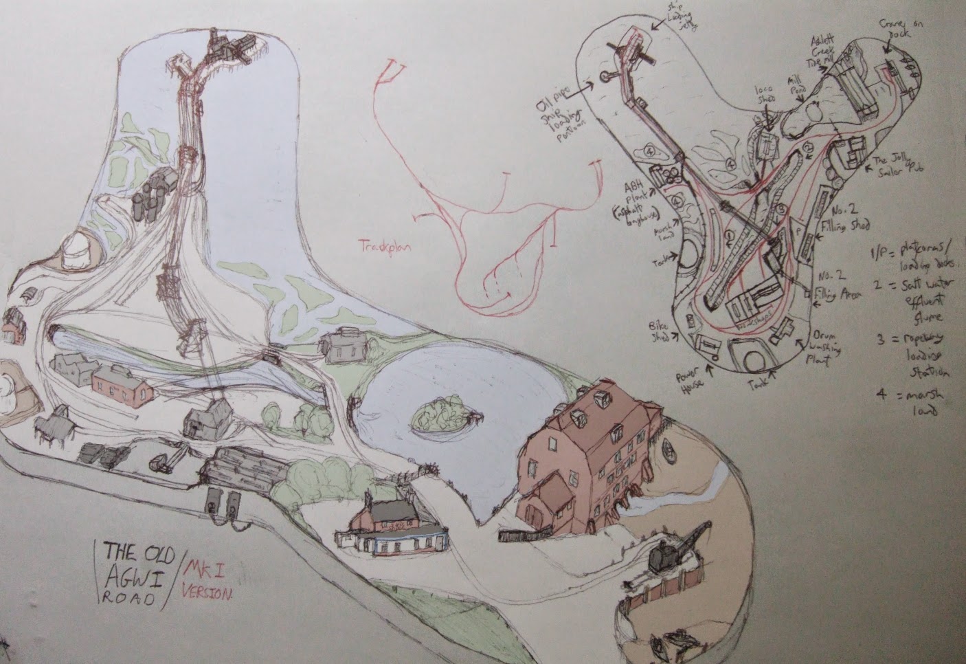
This is my initial (badly drawn!) plan for the layout. I am not happy with some parts of the plan (i.e. the bottom segment of the plan view) as it is too crowded on the board edge. Looking at the 3D sketch, on the right is Ashlett Creek (the mill, steam crane, pub, and mill pond can be seen). To the top middle you can see the loco shed on its own peninsula. The jetty at the top with its aerial ropeway running down the majority of the layout to the asphalt filling area by the controllers. The workshops can be seen below the salt water effluent flume (the stream!), with the power house (brick, far left) sandwiched between two small tanks. There is also a bike shed if you look close enough! Finally you can just about see the A.B.H siding and associated plant buildings (4 small silos and corrugated building at the beginning of the jetty). I have forgotten to show the aerial ropeway angled station which would be located around that area, roughly by the ropeway pylons in the middle of the layout.
Notes:
-
No indication has been given for the size of this layout - this is because I'm not 100% of that myself. But if I had to guess, imagine a circle of radius approx 3ft from the centre point of the layout?
-
Why have I gone for such a weird propeller shape? Firstly because I don't like boring rectangles, and secondly, I thought it a fitting tribute to my first layout based on the seaplane base at "Calshot"!
Things I plan to/might change from that above plan:
-
Adding an aerial ropeway angular station in the middle
-
Reducing the amount of buildings on the left hand side (in the 3D view), or maybe just rearranging it to look more pleasing to the eye!
-
Maybe add in a little bit of standard gauge...
If you got through all that, well done!
I'd highly appreciate any suggestions, comments or general feedback.
Don't forget the layout topic on NGRM-online
here for those of you that would rather follow a topic than a blog.
Thanks for reading!
Jam.
-
 2
2

3 Comments
Recommended Comments
Create an account or sign in to comment
You need to be a member in order to leave a comment
Create an account
Sign up for a new account in our community. It's easy!
Register a new accountSign in
Already have an account? Sign in here.
Sign In Now