

Series 252 on the banco de trabajo – Part 1

Entry posted by NGT6 1315
270 views
Evening all!
On Monday, I finally was able to submit to my long-prepared plan for tweaking the Renfe Series 252 electric which I originally presented in this thread.
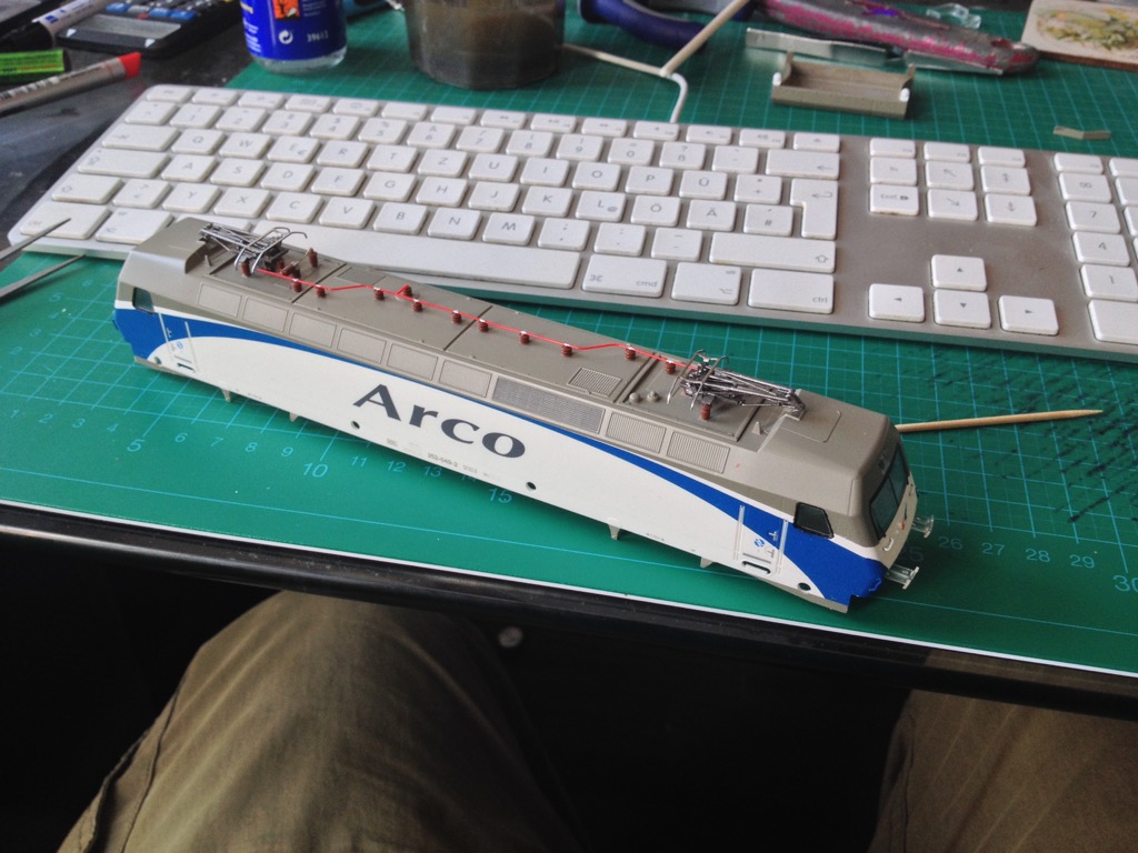
To refresh your memory: This is what I started with – 252-049 with the "Grandes Líneas" livery, which railfans sometimes refer to as the "Danone" livery, and billboard "Arco" lettering on the body sides...
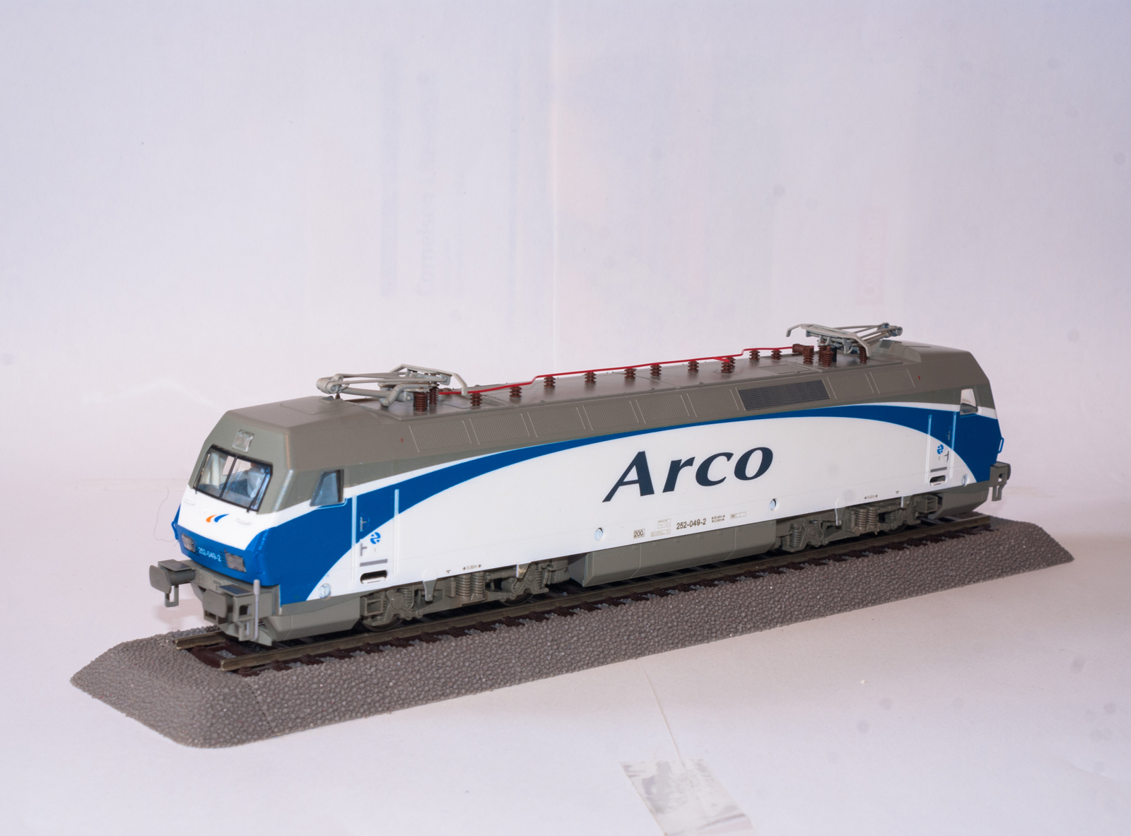
…and this should highlight those items I am planning to address:


But, in fact, I already deviated from that plan slightly!
Having checked the remains of a cannibalised Roco Schunk WBL85 pan from my scrapbox for possibilities of fitting, I noticed that Roco's pan represents a slightly different version with one straight control arm – the part connecting the front of the base frame to the upper arm ahead of the knuckle joint – in lieu of the Y-shaped control arm as utilised on the variant chosen by Renfe.
So, I remembered the pantographs being provided on the various Bombardier TRAXX models by Italian producer ACME having become much more prototypical over the years the company has been active – and that ACME do, in fact, carry the correct Schunk pantograph variant.
They do, however, not carry a version readily outfitted with the head used in Spain. Yet, I decided I could modify the Polish version easily enough to resemble the Spanish pan head...
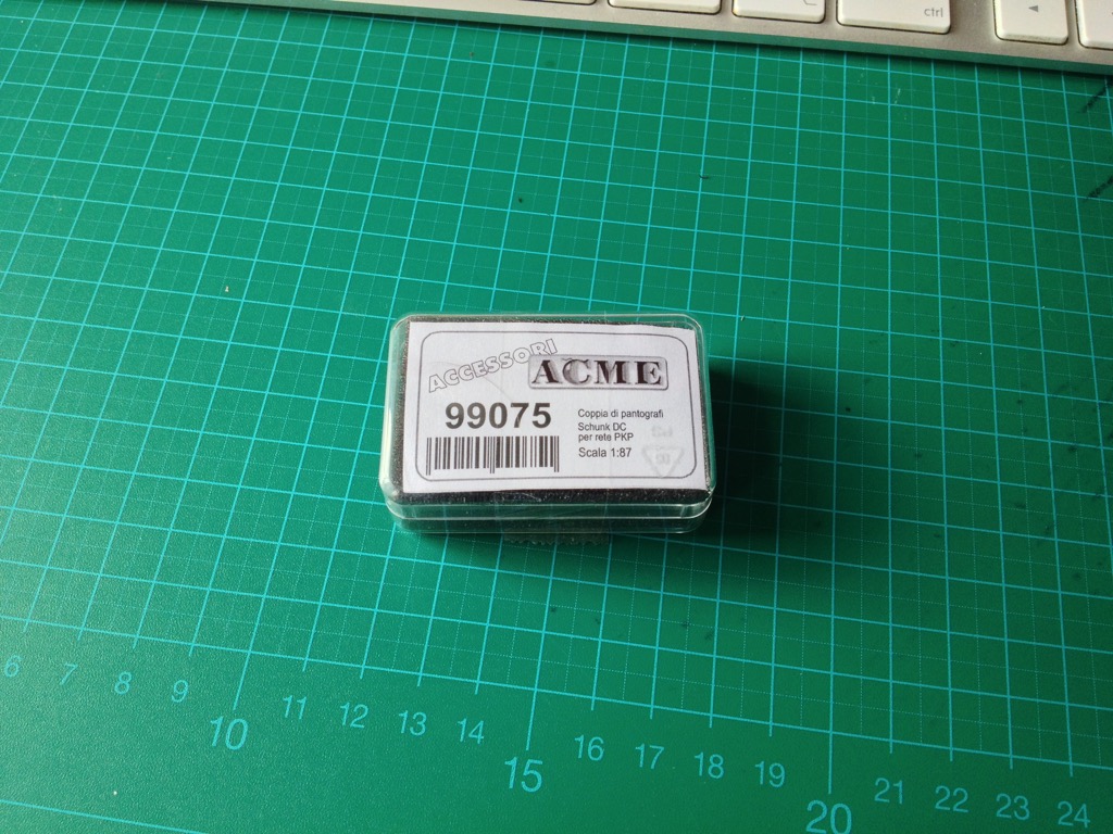
…so I ordered a set of Polish Schunk WBL pans from them.
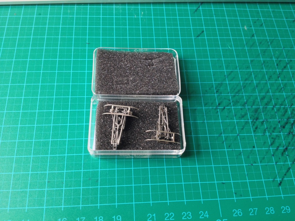
You can see that out of the box, the Polish pan heads have downward-curved guide horns which makes them easily recognisable. However, the Spanish Schunk pans have straight, downward-angled guide horns, as evidenced by, for example, this photo:
 Estrella 252-023 Renfe by Juanjo Rodríguez, auf Flickr
And for comparison, a closer look at the factory-fitted pans, which not only are devoid of any recognisable prototype but quite clunky as well:

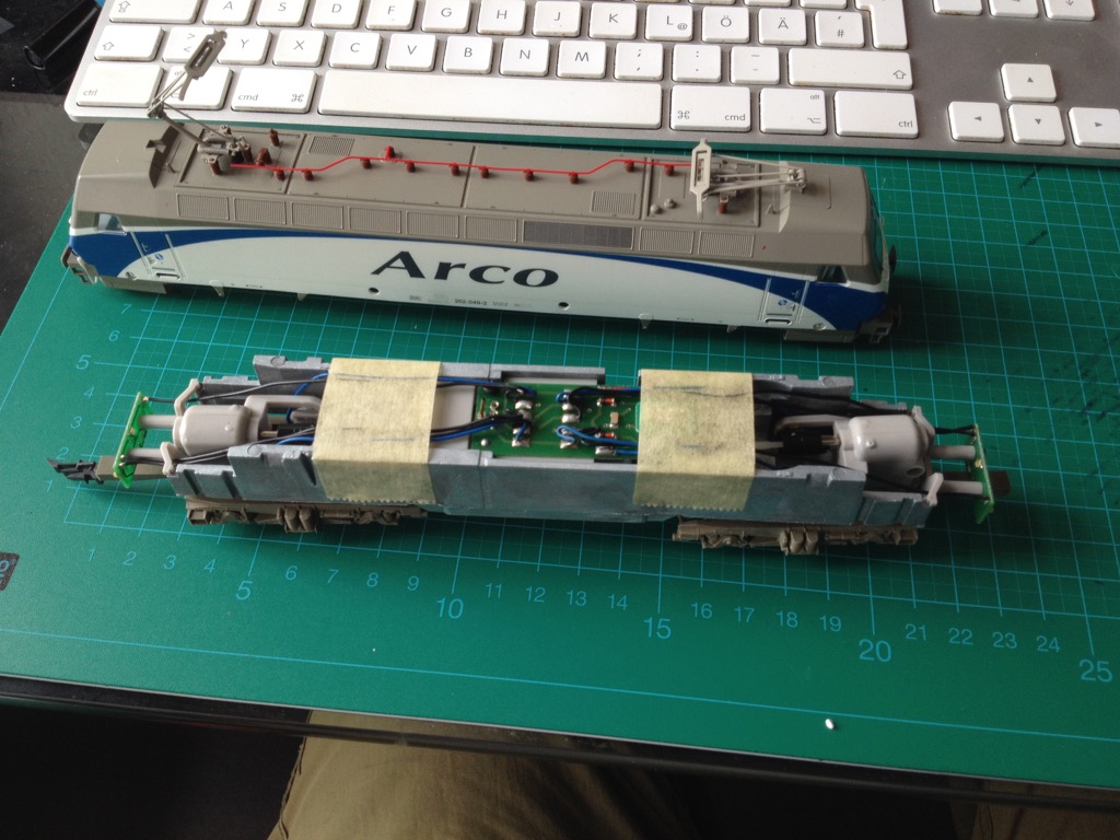
Pretty much all further modding work on this model is better carried out with the body shell removed. You can tell that the Mehano 252 really is a fairly simple model out of the box.
Most recently, I found myself considering fitting the loco with coupler extension mechanisms in lieu of the simplistic "drawbar" style coupler pockets attached to the outer ends of the bogies. To that end, I can tell I'd have to furnish an attachment base plate of some description. These would have to be glued in place on the outer ends of the chassis, below the outriggers holding the headlight PCBs in place. I do think this should be doable...
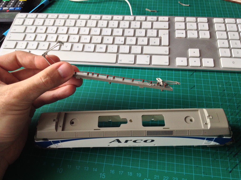
The rooftop element actually is an insert held in this recess by three screws, and must be unfastened in order to remove the pantographs.
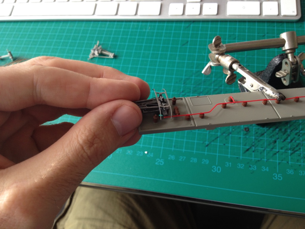
I had already realised that I would have to relocate the lateral attachment arms on the pantographs' base frames a bit to match the supporting insulators, which are arranged in a triangle with the centre apex pointing towards the loco's centre. The rear end of said frames would, as I decided, go directly on top of the inner insulator.
I determined that the lateral attachments would have to be shifted towards the cabs by 7 mm. Now, another reason why I chose ACME pans paid off: The base frames are actually made of plastic, so the attachment arms could be removed with a razor saw easily enough, and glued back on with CA. Any possible gaps would be filled by the glue itself, and sufficiently concealed by a bit of aluminium paint.
I then drilled small holes in the top sides of the lateral supporting insulators, widening them further by way of wiggling the drill bit slightly and the tip of a scalpel.
I had noticed it would be easier to first glue the lateral attachment arms to the insulators and only then basically "insert" the pan for fine adjustment. Only after that did I glue the pan to the attachment arms, relying on capillary action for the CA to seep in.
I don't claim to have been able to adjust the pans with micro-millimetre accuracy which I guess will barely be possible in any case, but I think good enough is good enough.
So, that would, basically, have been the first bits of modding I carried out on this model. Further additions are likely to follow in a while, so do stay tuned for follow-up postings!
-
 2
2

0 Comments
Recommended Comments
There are no comments to display.
Create an account or sign in to comment
You need to be a member in order to leave a comment
Create an account
Sign up for a new account in our community. It's easy!
Register a new accountSign in
Already have an account? Sign in here.
Sign In Now