

Infrastructure Showcase, Part 1: Pointwork and point signalling for trams

Entry posted by NGT6 1315
353 views
Evening all!
I originally posted the following text on my "Bw Leipzig Hbf West" blog in April but, in light of, shall we say, personal professional experience collected since that time, I thought it might be worthwhile reposting and amending it on here!
In any case, I suppose a bit of a preface should be sensible
German trams most commonly run under what could be called line-of-sight operating conditions, meaning that cars proceed on sight from one signal to the next, and that no train protection systems as would be present on railways are available. Such systems generally are installed only on grade-separated routes of various light rail networks throughout the country, such as those in Hanover, Frankfurt or Stuttgart.
That, of course, means drivers must generally observe regular traffic rules on street-bound routes, and trams must be outfitted with the same basic arrangement of headlights, brake lights and turn signals as automobiles. Obviously, trams must, given their weight, also be outfitted with highly effective brakes to be able to operate safely under these conditions and among automobiles. This is why they are generally outfitted with magnetic track brakes to allow for very short emergency stopping distances.
Generally, tram and other light rail systems are subject to the regulations laid out in what is colloquially called "BOStrab" in German, which is shorthand for "Bau- und Betriebsordnung für Straßenbahnen" and best translated as "Tram Construction and Operating Ordinance." This is a set of regulations completely separate from the "Eisenbahn-Bau- und Betriebsordnung" (Railway Construction and Operating Ordinance), abbreviated "EBO" and applicable to all "heavy rail" systems in Germany.
Most commonly, rail vehicles comply to only EBO or only BOStrab but not both at the same time. Exceptions to that rule can be found, for example, on the suburban network in the Karlsruhe area or on the Saarbahn network, either of which constitutes a tram-train system. Basically, these tram-trains must therefore, among other parameters, meet railway crashworthiness and impact resistance norms, and be outfitted with wheelsets suitably profiled for both railway and tram track geometries.
That, however, is a subject worthy of separate coverage, and if you speak German and can also handle technical vocabulary, I recommend you have a look at https://www.vdv.de/bostrab.aspx where the Association of German Transport Operators offers various official guidelines for practical applications of BOStrab standards for download. This includes a paper on track and wheel geometry, titled "Technische Regeln für die Spurführung von Schienenbahnen nach der BOStrab."
Let us begin with this photo…
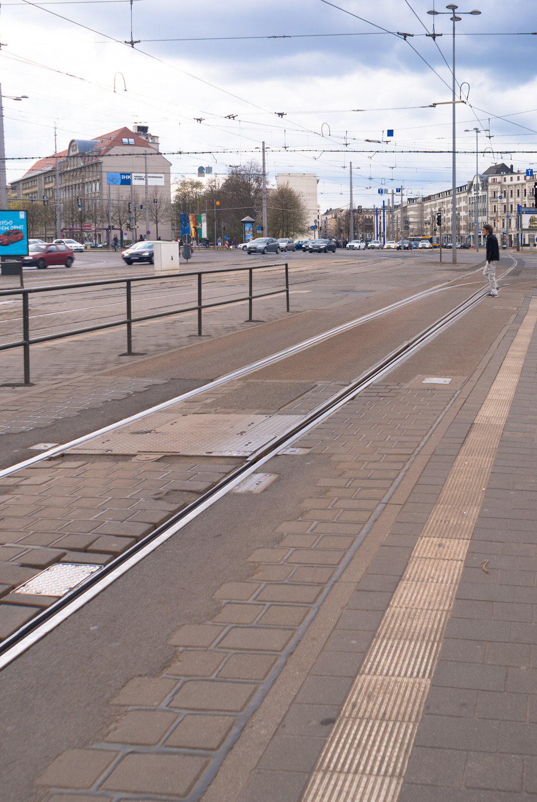
Paved-in track is generally built with grooved rails while grade-separated tracks can be built with either Vignoles or grooved rails. On paved-in routes, points therefore differ a bit from regular points, which I'll get back to in a few moments.
In order to increase route capacity at intersections or other key locations, it is now quite common to provide what is commonly called "sorting points." Technically, these are, basically, very long points with the point blades being placed far ahead of the diverging track. Assuming two cars following each other but working different lines, this allows for either car to be properly routed in advance of passing an intersection in order to maximise throughput for each signal cycle.
Taken at the Goerdelerring intersection, the straight track proceeds into Jahnallee and is used by Lines 3, 4, 7 and 15, while the diverging track turns onto Pfaffendorfer Straße and is for Line 12. Similar sorting points, some even longer, also exist in other locations in the city but some can be photographed safely only aboard trams.
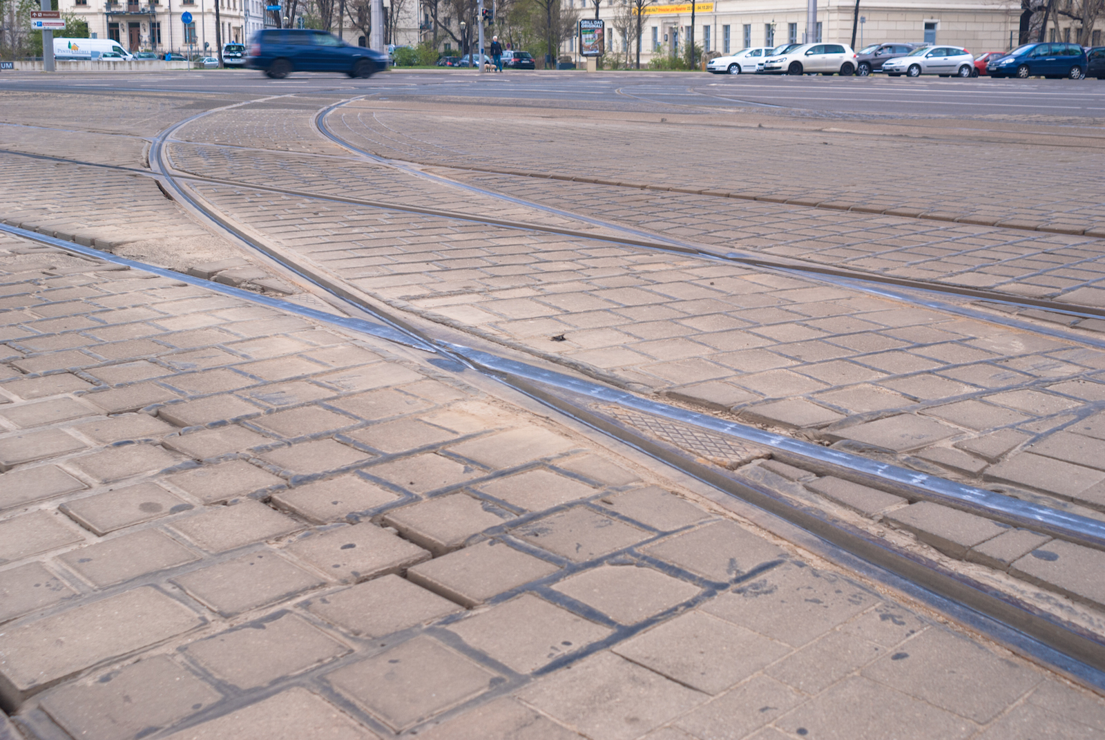
While no sensible alternative to grooved rails exists for paved-in track, this type of rail does, technically, entail an increased risk of stones, snow, ice or other materials getting stuck in the grooves. On points in particular, this could result in derailments, so in order to counter this risk, the rail elements utilised for points are fabricated with much shallower grooves.
As you can see in the above photo, also taken at Goerdelerring, this configuration is most prominently evident at the common crossings. Looking closely, you can also spot the stock rail grooves varying in depth in between the common crossings, where they are most shallow. This also means that effectively, the common crossings are flange bearing, so that the wheel flanges rather than the treads carry the car weight. I understand this also has the additional effect of extending the common crossings' lives.
*************
One remark which I think I should make up front is that while the Tram Construction and Operating Ordinance does outline a common framework of guidelines as to the purpose and appearance of tram signals which is valid throughout Germany, the Technical Supervision Authorities ("Technische Aufsichtsbehörden", TAB) in the individual states as well as the operating companies themselves are at liberty to request and implement adaptations to suit specific requirements posed by local conditions which the general BOStrab framework could not cover.
Such individual adaptations which are specific for one particular tram system are outlined in local application guidelines usually designated "DFStrab", spelt out as "Dienstordnung für den Fahrbetrieb – Straßenbahn" and suitably translated as "Operational Tram Service Regulation." Ours at LVB looks like this:

…and consists of a 74-pages main part and several appendices for signalling, depot and shunting operations, as well as operating manuals for the four car types currently in our inventory.
Fundamentally, tram signals should be understood largely as pure route signals, as opposed to German railway signals which generally imply specific running speed information as well.
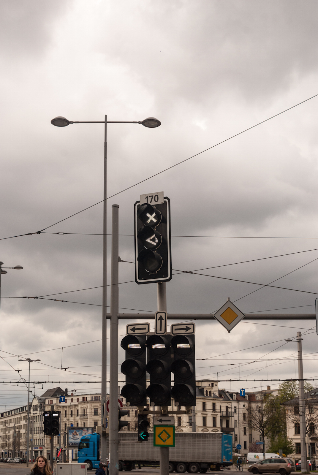
These route signals are generally referred to as "F signals", spelt out as "Fahrsignale" and extended to the individual aspects. On multi-route junctions such as this one, there is generally one signal screen for each route which can be set from this location, and indeed relevant only to that individual route. This, of course, means you must observe the screen relevant for the direction you need to take. In a sense, this makes them very similar in principle to traffic lights.
I will, however, further outline these principal route signals in a different posting!
Also take note of the screen set atop the cluster of three "F" signal screens, and lettered to refer to the point from the first photo, 170. This is, essentially, a point signal, obviously useful to inform drivers whether the proper route for their turn has indeed been set.
As tram points must no longer be set by way of OHLE current sensing contacts (which were disallowed in the mid-1990s), route setting is now commonly performed automatically through induction-based telemetry with transmitter units on cars and ground-mounted transceiver circuits. These transmitters are tied to the Integrated Onboard Information System – "Integriertes Bordinformationssystem" or "IBIS" in German – so that as a driver, you need to enter the line and turn number through a cab terminal for the car to be properly routed for the duration of the shift.
The transceiver circuit is placed sufficiently far ahead of the point, and marked with the St 2 plate:
If, for some reason, the proper route was not set automatically, you can manually set points either by way of corresponding buttons on the IBIS terminal or control desk while within transmitting distance of the ground-based transceivers – or by way of a simple lever carried in each cab and actually referred to as a "spear" in operating parlance.
This also means it is essential for drivers to approach points only at such speeds that they can come to a halt ahead of the point blades with a standard service brake application. Generally, in Leipzig, we must observe the following speed limits for passing points:
-
Manual point, facing: 15 kph
-
Manual point, trailing: 25 kph
-
Powered point, facing and trailing: 25 kph
…with the official reason for this procedure being that it shall enable drivers to positively ascertain correct route setting and point blade alignment prior to passing any point. There is no possibility for Control to interact with any points on the routes under this kind of decentralised point setting. Light rail systems, such as those mentioned further up, do generally have centralised point control, and thus are much more similar to railways and their signal boxes in this respect.
For us, it's also essential to know what to do when a powered point has failed, which is usually recognisable when the point signal – or "register", as we call it – has turned completely dark or shows an erratic aspect. First of all, it is not permitted to simply proceed across a "dark point" without authorisation.
What we should always try to do when stood ahead of a dark point is to try manually setting it with the lever we carry aboard, or, if necessary, clean out the rail grooves around the point blades with a broom which we also have aboard. In many cases, this will allow the point to achieve proper alignment and locking, as it will often just be some dirt to have fouled the blade alignment sensors and/or the point blades. In this case, the register will light up anew, confirming successful setting and locking.
If a manual reset and cleaning does not establish a lit register but the blades are properly aligned, we are to notify Control accordingly, who may then authorise us to proceed with proper caution – which comprises walking speed until the point has been completely passed. It is also possible, and indeed common practice, for Control to summarily authorise all turns having to pass a dark point accordingly once it has been reported and repair measures have been ordered, so as to keep radio communication clear.
At this point, I should also mention another important item to keep in mind when passing points – especially those points we summarily call "left-hand points." Put simply, this is any non-locked point where the diverging branch intersects the opposite track and which would therefore entail colliding with an oncoming service if it should be falsely set, or indeed reset itself while passing. This interpretation thus also applies to any failed powered point where the diverging branch intersects the opposite track.
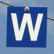
Consequently, it is generally forbidden to pass a non-locked left-hand point simultaneously with an oncoming service, which in practice means that the service to perform a facing point movement must wait ahead of the point until the opposite service has passed. However, such points may be signed to allow simultaneous passing, utilising the W 22 plate, as it is called in Leipzig:
And there is even more to observe with regards to manually set points!

Generally, manual points do not have to be reset to any specific position unless this plate, called W 21, is present. Of course, this is another reason why you should adjust your speed such that you can check for proper point alignment prior to passing, and come to a safe halt and reset it if necessary. The arrow on the W 21 plate will always point in the direction defined as the standard route for that specific point, and means that if you needed to pass it on the non-standard route, you must stop and reset it immediately upon passing.
As for the point signal in the earlier example, the variety used in Leipzig is, actually, an example for how individual operators may implement modifications to the general BOStrab framework.
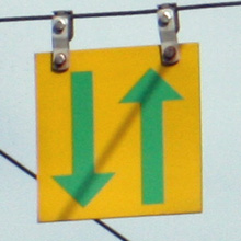
But, first of all, take note of the "X" symbol lit up at the top of the screen. This is the "W 0" aspect indicating that the points are currently electronically locked for the next tram to pass it and that none of the following trams can reset the points until they have been cleared. To that end, a magnetic resonance circuit is placed beyond the point blades to detect the large lump of ferromagnetic metal that is a tram, and which re-enables the setting circuit once the point has been cleared.
Now, looking at the first image in this posting, you will notice that the point in question has a straight branch and a right hand branch. However, the indicator in this example is equipped with aspects for left and right hand branch.
While BOStrab does specify an aspect for the straight branch, LVB have chosen to normally utilise only the aspects for left and right on point indicators, so that in this example, the "left" branch actually refers to the straight route.
The standard aspect for the straight route would appear as an upward pointing arrowhead. Exceptions to this rule exist only in four specific locations where we have Consecutive Point Control implemented, which I will illustrate at a later time.
It is also important to keep in mind that there are actually two variations for each of the point indicator aspects: Without the straight "bar" at the open end of the arrowhead, the point is indicated to not be mechanically locked in position, imposing a 15 kph speed limit. When the bar does display, the point is mechanically locked, allowing regular running speed.
This means there are the following point aspects as per BOStrab:
W 1 – straight, not locked
W 2 – right, not locked
W 3 – left, not locked
W 11 – straight, locked
W 12 – right, locked
W 13 – left, locked
At this time, we only have powered points with mechanical lock in Leipzig, so only the W 11 through W 13 aspects apply.
Let us also have a look at this signal board atop the ear end of 1331 (but actually above the opposite track):
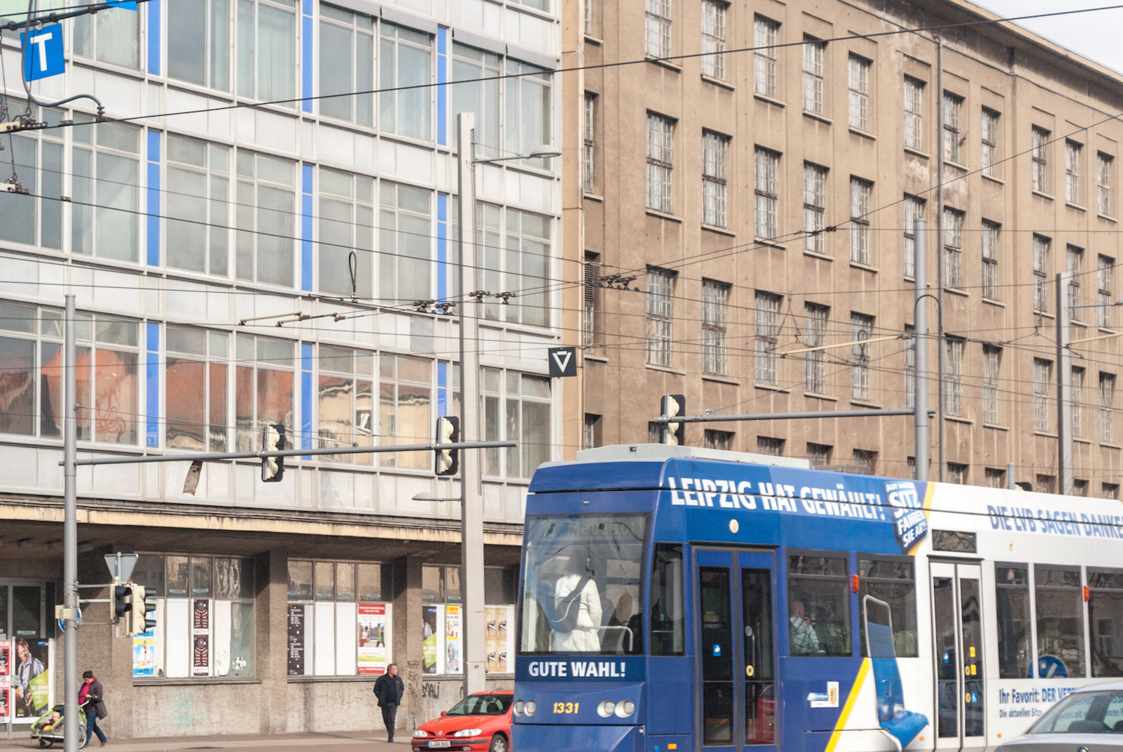
This board, designated W 14, indicates that the point thus signed is powered and may not be split from the trailing end, so that if for any reason you need to reverse through this point, you must, if necessary, manually reset it prior to passing it. Obviously, the W 14 plate is only visible as such from the rear end of the car.
I think this will be it for the moment, but do ask if you have any questions!
-
 1
1

0 Comments
Recommended Comments
There are no comments to display.
Create an account or sign in to comment
You need to be a member in order to leave a comment
Create an account
Sign up for a new account in our community. It's easy!
Register a new accountSign in
Already have an account? Sign in here.
Sign In Now