

Entry posted by londonbus
1,232 views

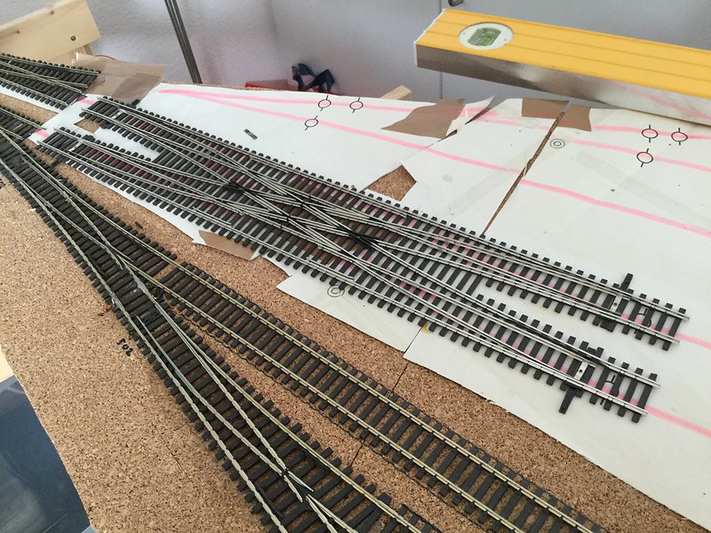
Wife's gone away to help out with little ones, leaving her other infant alone in the railway room. Attention turns to the Shinohara Double Crossover, Code 100, No.6. I bought this recently from Scalelink and it fits the purpose of the Northern Bay Crossover nicely. Peco quality it is not, however with some experimenting i've got it do do what I want. The option of butchering 4 points and a crossover would have just been too time consuming and fiddly, and probably no cheaper.
The first thing I noticed with my continuity meter is that the entire frog and full length of the switch blades are live. The polarity is supposed to change by using a quite flimsy connector under the end of the switch blade. To add to the potential for failure the fishplates between the frog and the switchblades don't appear to give a completely satisfactory connection. Although I should point out that the crossover works fine out of the box, in my view it's only a matter of time until it doesn't. So I set about a belt and braces solution.
The points are not self-latching, i.e. they don't click shut like the PECO ones do. This is not a problem for me anyway as i'll be using COBALT stall motors. The additional benefit of the Cobalts (and probably the Tortoise, although i've never used these) is that you have output to change the polarity of the frog a the motor switched the points.
The points are nicely insulated where they need to be and this means I can incorporate the four occupancy detection zones with little bother. I just have to make one cut on the black line (as the red is common), otherwise the "Up" direction (The top line in the above picture) would join the two detection zone. This would have the unwanted result of showing the "Up" throat pointwork as occupied if there was a Loco or coach / wagon drawing a current in Bay 1. It's taken forever to understand this. But now it has sunk in.
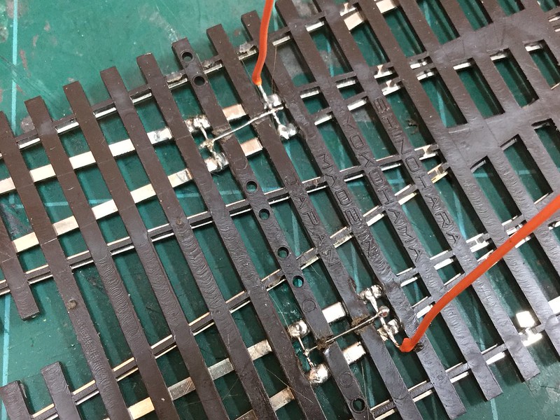
In the image above you can see how i've connected the frog rails together and also made a connection over the joint where the fishplate was the only way of conducting power. So that the wire (Excess wire supplied with the Peco three way point!) that makes a more secure connection doesn't sit proud of the sleepers I cut HALF WAY through the plastic to create a small channel. Dremel on low and very careful not to cut completely through the sleeper. The wire will then go to one of the four Cobalts to received the correct polarity power when the points change.
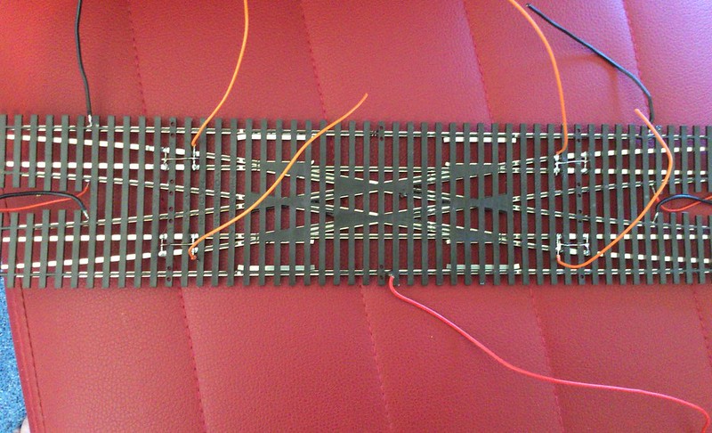
I quickly clipped the sleepers where you attach point motor as they are not flush with the sleepers (just as on the PECO points too). Lastly I soldered on the droppers, gapped the rail (in the middle / top black) and stuck it down with Copydex. Hopefully it'll work and I won't have to take it up again. All in all about 2 hour work with tea breaks. Lunch break over - back to work.
-
 3
3

4 Comments
Recommended Comments
Create an account or sign in to comment
You need to be a member in order to leave a comment
Create an account
Sign up for a new account in our community. It's easy!
Register a new accountSign in
Already have an account? Sign in here.
Sign In Now