
Peckett "Y" Class - Starting to come together

Entry posted by 2mmMark
659 views
The previous instalment finished with the motor about to undergo some surgery to shorten the shaft. Motor shafts are almost always hardened steel so regular wire cutters will make very little impression on them but the shaft will certainly leave an impression on the cutters. The best way to trim the shaft is with a cutting disc in a minidrill. This is a little risky so sensible safety precautions are strongly recommended. Eye protection just in case the disc breaks up is required and definitely think about a safe way to hold the motor during the process. In this case, the photo below shows how I did it, by holding the other end of the shaft in a pin chuck, which has the benefit of allowing the cut end of the shaft to be give a slight bevel to tidy up the cut. The cut end is simply rotated while gently touching the cutting disk at an angle. Fingers are safely out of the way of the disc.

Note that the disc isn't spnning when I took the picture. Even I'm not mad enough to try that! In this case, I'm using a carborundum disc as I beleive they give a neater cut. Diamond discs are an alternative but they seem to "bounce" a little bit and in my hands at least, don't cut so nicely. In the previous instalment, I mentioned a flywheel, which I turned up on the lathe. It's just a piece of brass rod, nothing fancy. Alternatively, nicely made flywheels are available off the shelf from Tramfabriek or N-Brass.

The other end of the motor had the work affixed. For this I used Granville thread-locking fluid from Halfords, as recommended to me by Sven van der Hart of Tramfabriek. The bond is good but can be broken if required for dismantling. Some of the Loctite compounds I've used in the past are quite permanent.

At this point, the power unit comprising motor, bracket, worm and flywheel is ready to use. The next thing is to arrange an electrical connection between the frames and the motor contact tags. A very simple solution was to trap some springy phosphor-bronze wires between the frames and spacer. As the spacer is plastic, all that was needed was to cut a groove in which the wires are trapped by the frames. Underneath the spacer, in the axle aperture, the wires are just bent over to trap them in place. The following set of photos should make things clear.


The feed wires are easy to simply spring apart if it's necessary to remove the motor. In this case, the motor was in the right orientation to give forward movement with the right hand rail positive. If it wasn't correct, all that's needed would be to rotate the motor 180 degrees.
The body has had some attention. It's gained a set of large headed industrial buffers and foot steps. The buffers are regular loco buffers with an extra etched head soldered on. Looking at photos of various industrial locos, the real thing also extended buffers in this way. Probably not with 60/40 tin-lead solder though. The footsteps are lost wax brass castings from the N-Brass range.


Putting the steps and buffers on required a bit of shaping to be done to the PCB underplate (mentioned in the earlier "Bodywork" section). Some 14BA nuts were soldered to the copper side to accept the fixing screws of the chassis


A couple of brass pins were fitted into the space to provide some alignment for the chassis. In this view they can be seen just ahead of the worm & gear.
In due course the PCB plate will be glued in place rather than soldered to avoid any risk of the copper delaminating. A glue joint here will be amply strong enough. As mentioned previously the edge of the PCB represents the footplate valance.

Some satisfying progress made, I feel. What has become apparent now is the emptiness of the cab. It looks like some representation of the backhead and a brake standard will be required.
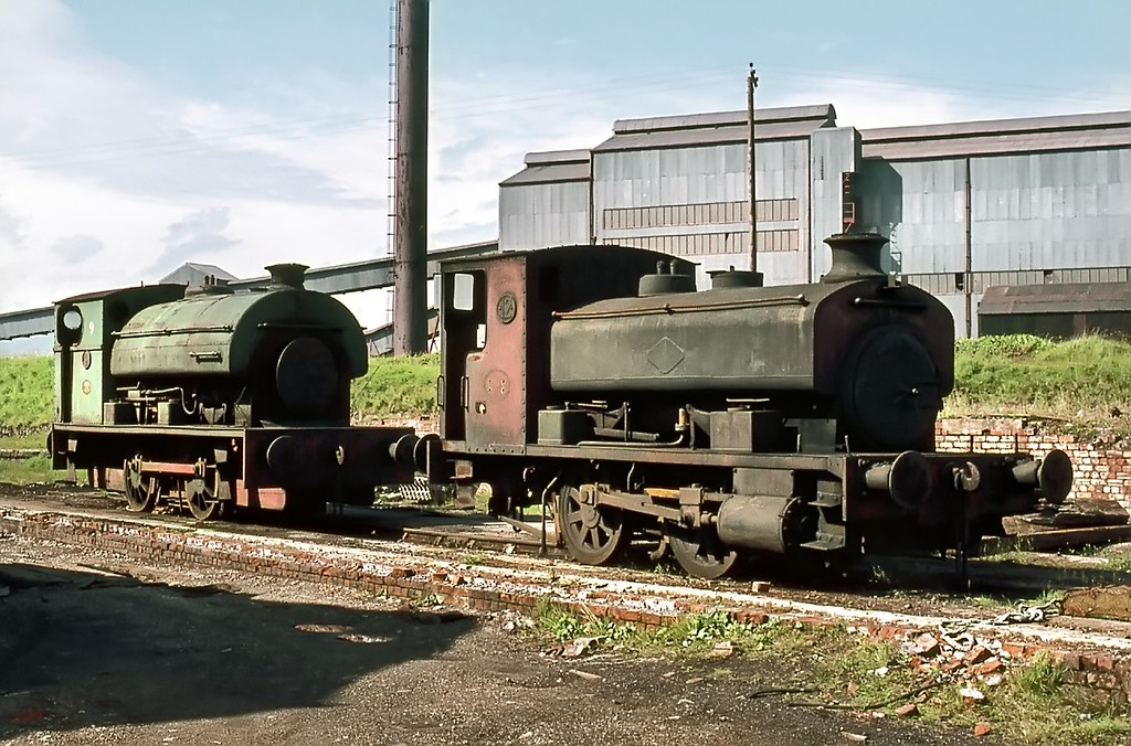
I've also found some photos online of a similar loco to mine, not identical but they certainly give some idea of how it could be finished.

From Flickr, this image was taken in 1967 by John Wiltshire at the Millom Ironworks in Cumbria. An inspirational image. It gives a good idea of what additional detail remains to be added.
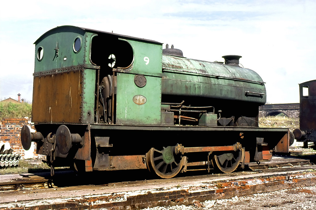
Also on Flickr from Gordon Edgar are these images of the same loco, showing some detail differences.

Mark
-
 10
10
-
 10
10


0 Comments
Recommended Comments
There are no comments to display.
Create an account or sign in to comment
You need to be a member in order to leave a comment
Create an account
Sign up for a new account in our community. It's easy!
Register a new accountSign in
Already have an account? Sign in here.
Sign In Now