


Entry posted by richbrummitt
411 views
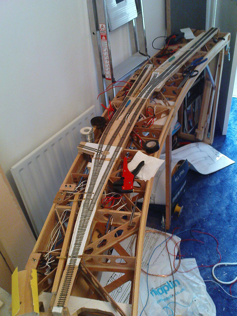
I've lost count of how much I've spent on wire, and yes it looks almost exactly like last time you saw it. It is however fully wired up. Unanswered questions still include: Why does it all take so long; and is it possible to make it neat? Here's a gratuitous picture from the other end of the layout.
I have used 3PDT switches (a 4PDT in one case) to allow the track to be double isolated unless the correct route is set. This should, in theory anyway, work just like insulated turnouts - only better. When I built a previous layout with live crossings using just a SPDT switch for the polarity I regularly ran into a short circuit. The idea for the arrangement as described is to remove this as a possibility! The catch points are operated by a SPDT switch which knocks the feed out to one rail so you have to change these too.
The cross baseboard connection is permanent (the boards are permanently connected. I made four four core cables up with lengths of heatshrink. Two for these and one each for the PSU and controller connections. The latter are plugged into DIN sockets on the underside of the small central piece with the middle legs on. Hopefully it will still fold up correctly!?
I haven't tried it out yet, but am looking forward to playing trains on my own layout. Then it will be back into the garden for further woodwork, basic landscaping and some initial colouring.
2 Comments
Recommended Comments
Create an account or sign in to comment
You need to be a member in order to leave a comment
Create an account
Sign up for a new account in our community. It's easy!
Register a new accountSign in
Already have an account? Sign in here.
Sign In Now