

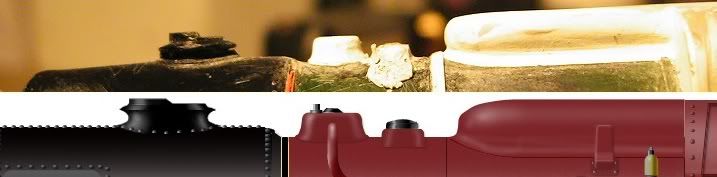
Construction Stages - LMS 6399 FURY

Entry posted by Knuckles
1,878 views
Here is a massive paste of the construction for Fury. I'm still getting used to the layout of RMweb so forgive my shotgun method of posting if it's crap. Please forgive the 2nd nature of the below posts. It's all compiled from the other forums but now presented here for you.
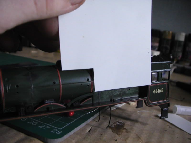
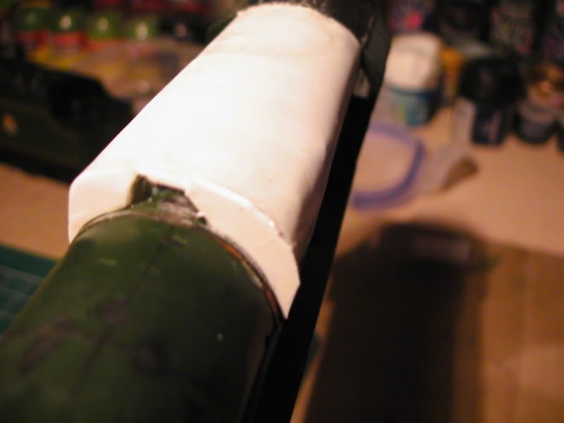
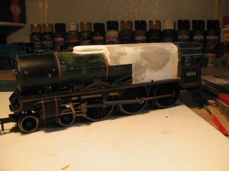
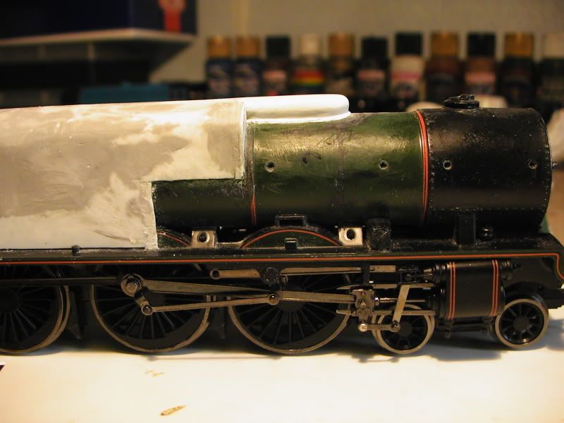
I have started with Bachmann's parallel boiler Royal Scot model as a base. The model is nice enough but a little lacking in detail and proportion if you ask me, but never mind. I removed most of the detail and pipes etc and a boiler band. I used balsawood to make rough formers for the one peice plasticard wrapping. The formers have been filed to shape and the wrapping..well, wrapped around!  Took a few attempts to get it looking right which is why there are a few chronological errors in the pictures. The pictures show up all the bad points but it'll be ok in the end, at the cab it is too high as shown but it presses down, just need to fix it. This is i think the most important peice of the whole structure, as long as I get this right everything else will follow.
More plasticard and Evergreen strip is on it's way in the post.
As new
Detail removed and formers added
Wrapping
-----------------
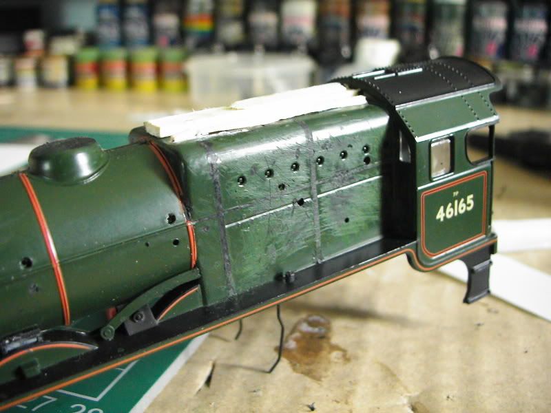
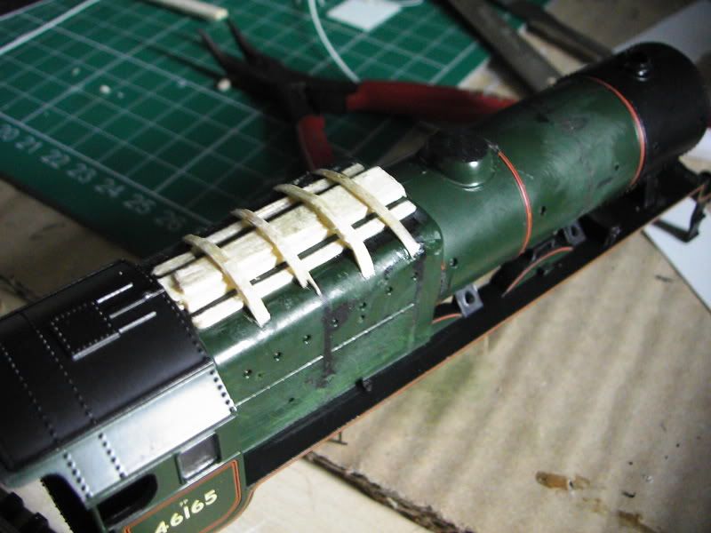
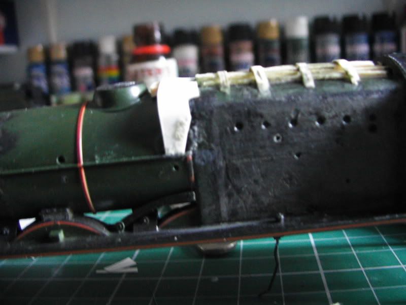
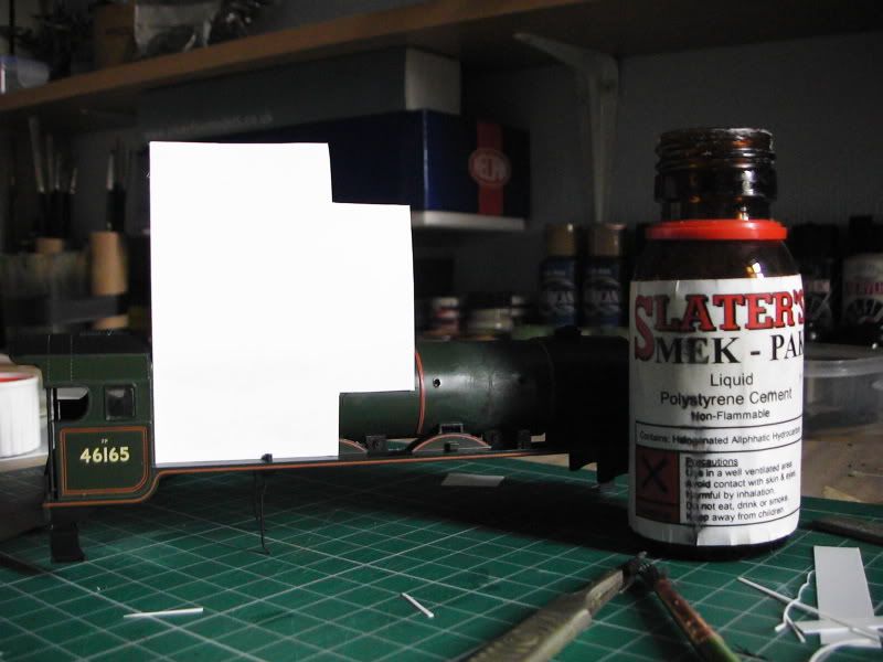
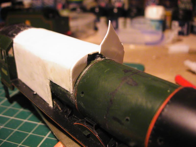
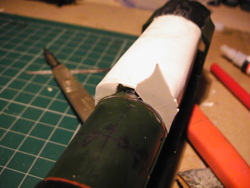
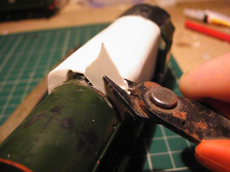
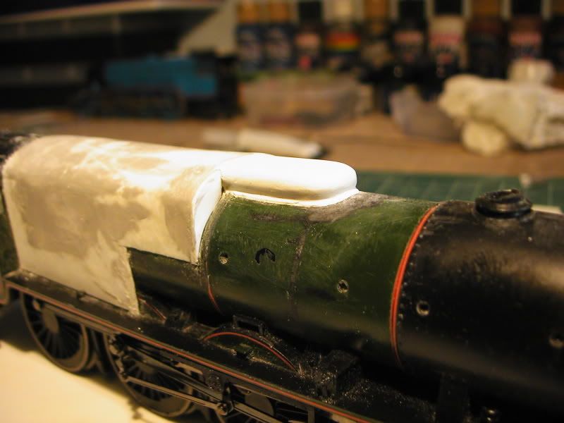
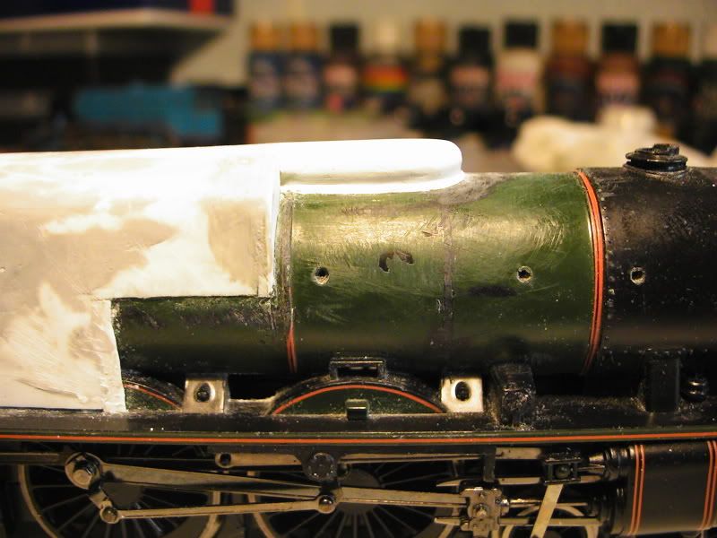
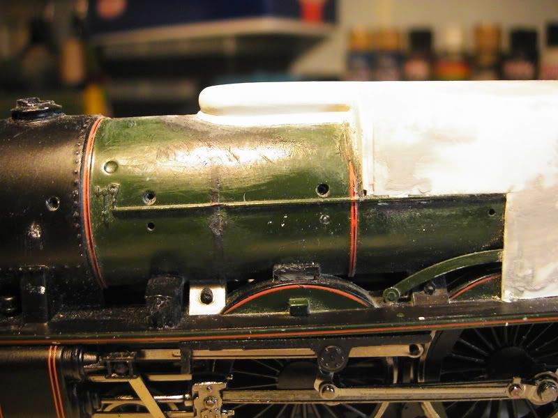
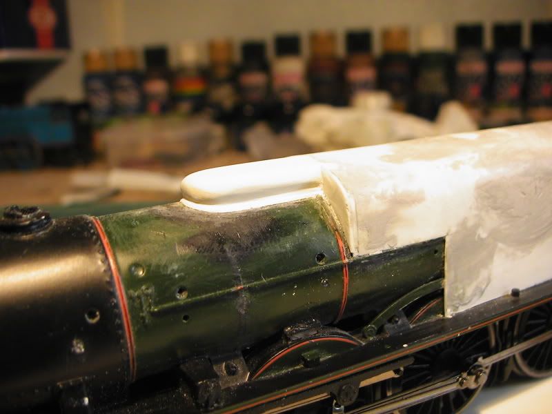
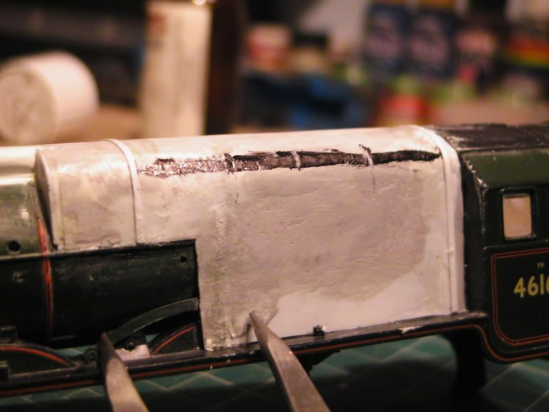
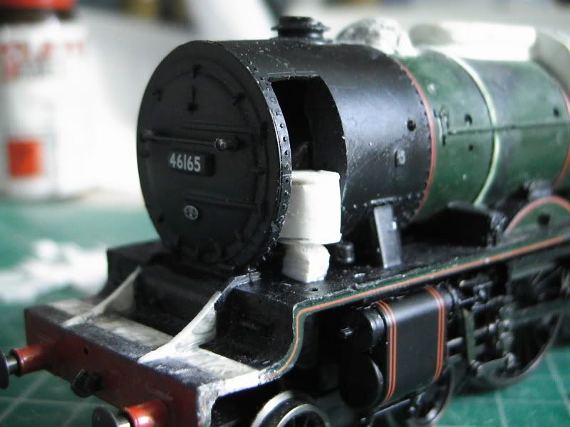
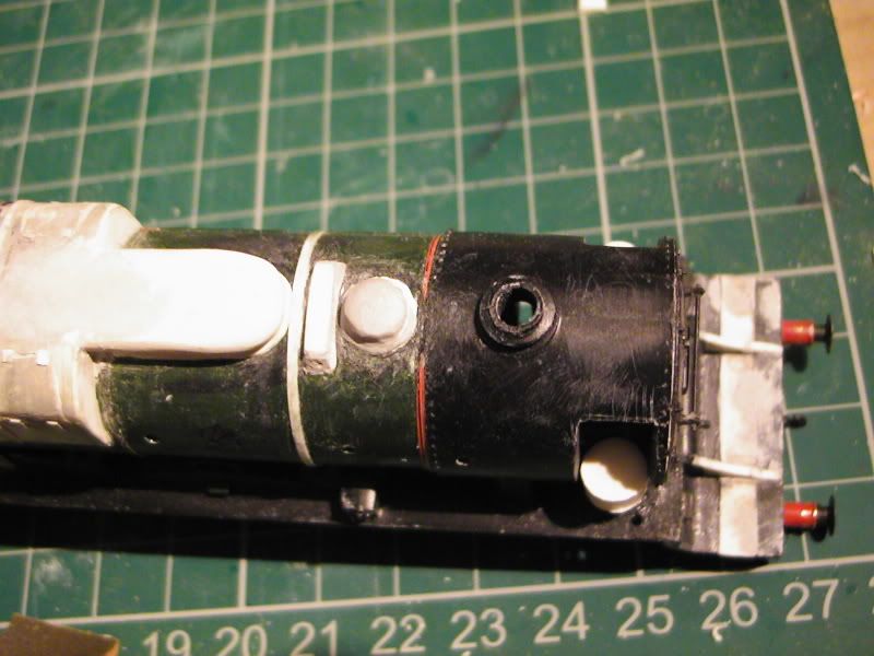
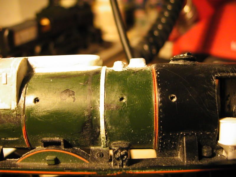
Ok guys, the top of the firebox cab join is in process of being fixed. It's been glued down and I'm now waiting for the miliput to dry so I can shape and file it all smooth - I had to fill a few holes in where the thin plasticard dishaped itself slightly due to the glue. it's looks a terrable mess currently but I know once I'm done it will be fine. You may also notice the sides of the wrap around at the front have been extened by roughly 1.5mm's, the join is visible on the photographs, made sure of that. It would help if I had a proper paper scale drawing on my desk to set my calipers to but I haven't so for now I am estimating by eye from photpgraphs and scale'ish' drawings on computor screen. i still rekon when all is completed it'll be fine though. Seeing as the base model isn't amazingly accurate in scale and proportion I don't think it will turn out too bad! We'll have to see.
I have already explained the work on the firebox wrap around so I will continue with the other bits, in hindsight though I think a think brass wrap around would have been far better, but never mind. Always learning.
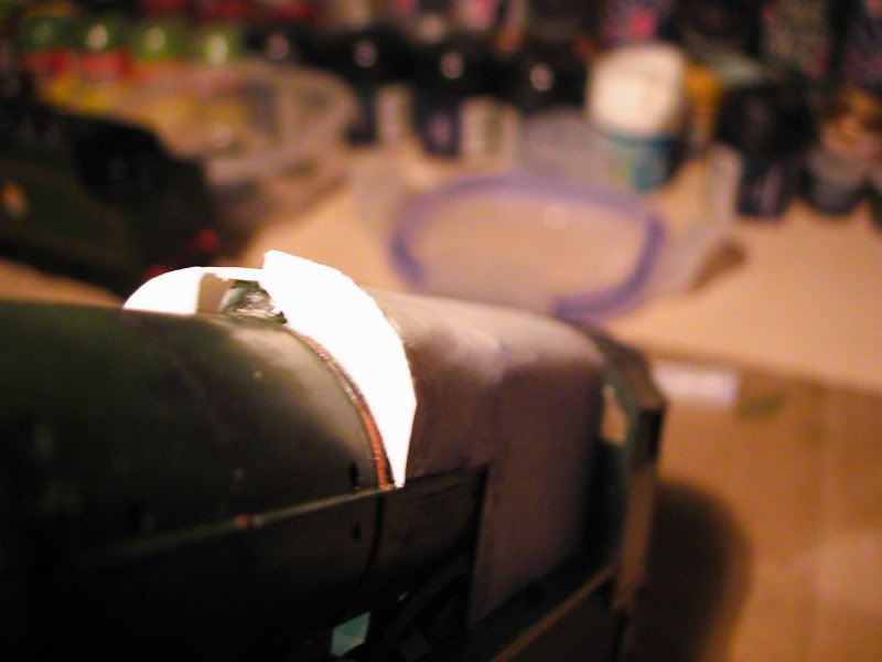
Currently looks dire, but wait until it's done.
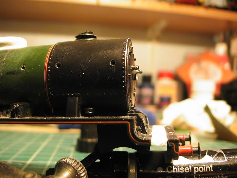
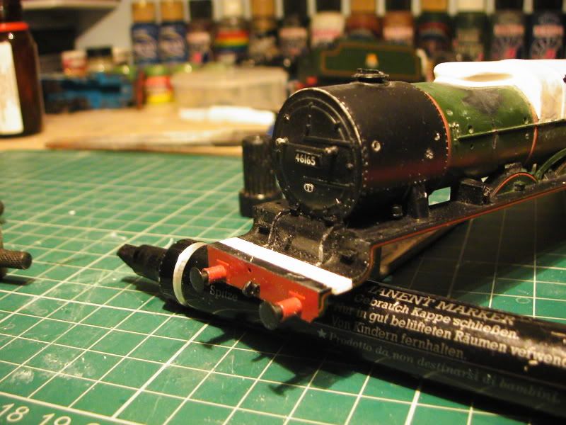
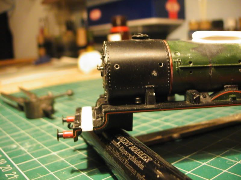
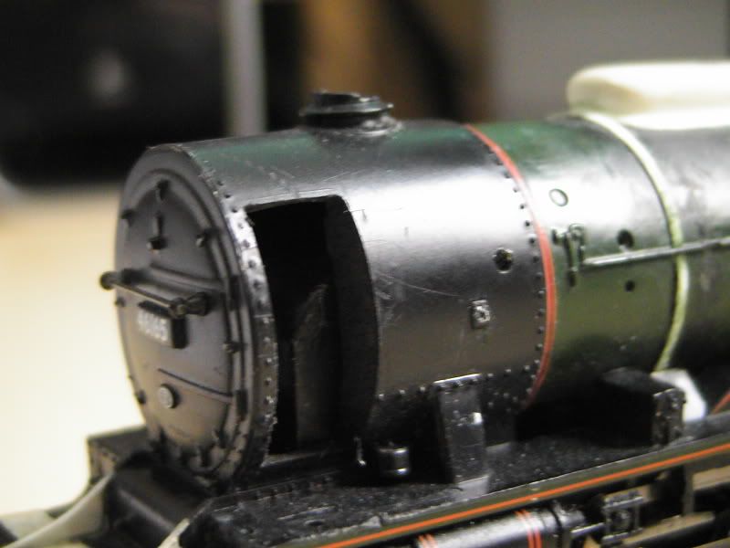
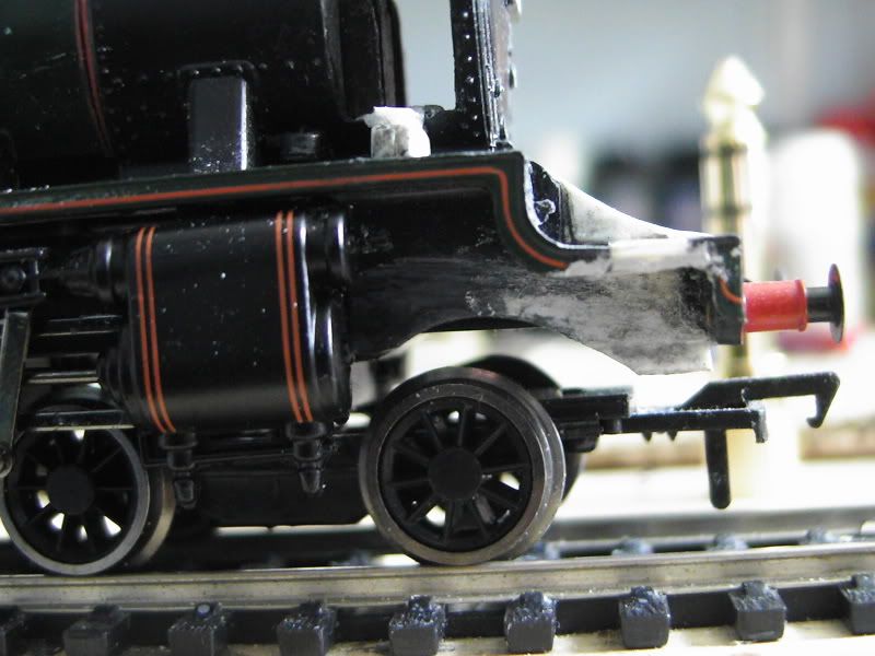
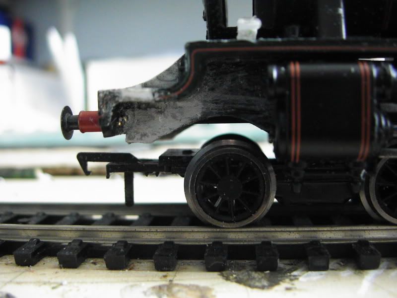
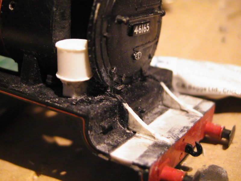
Look at photographs and drawings it seems the bufferbeam needs extending. This being thecase I wished to retain the steps that are moulded onto the whole body. A series of careful scores with a Swan Morton scalpel blade (handel number 3) followed by a few underneith cuts did the trick better than i could have hoped. Usually when I remoeve detail i destroy it, but seeing as I wished to retain this detail I had to try this out - win.
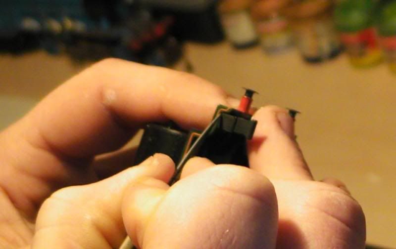
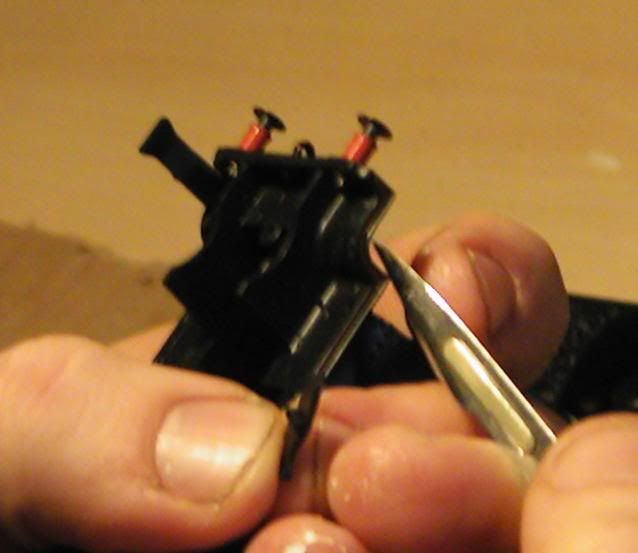
Next it was a case of brutality, bye bye!
Roughly where the bufferbeam should be when finished.
Edit: After reading this I noticed it's full of typo's but I cannot be bothered to amend things yet.
--------------
A mini bashing lesson.
I was hoping to have more done at this set of pictures but I need more time to decide how to do the dome.
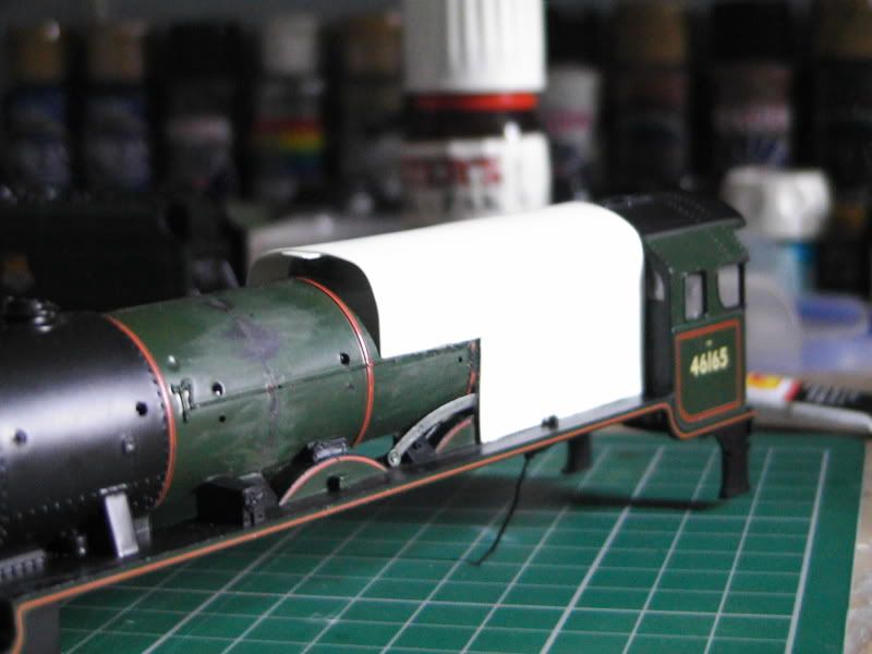
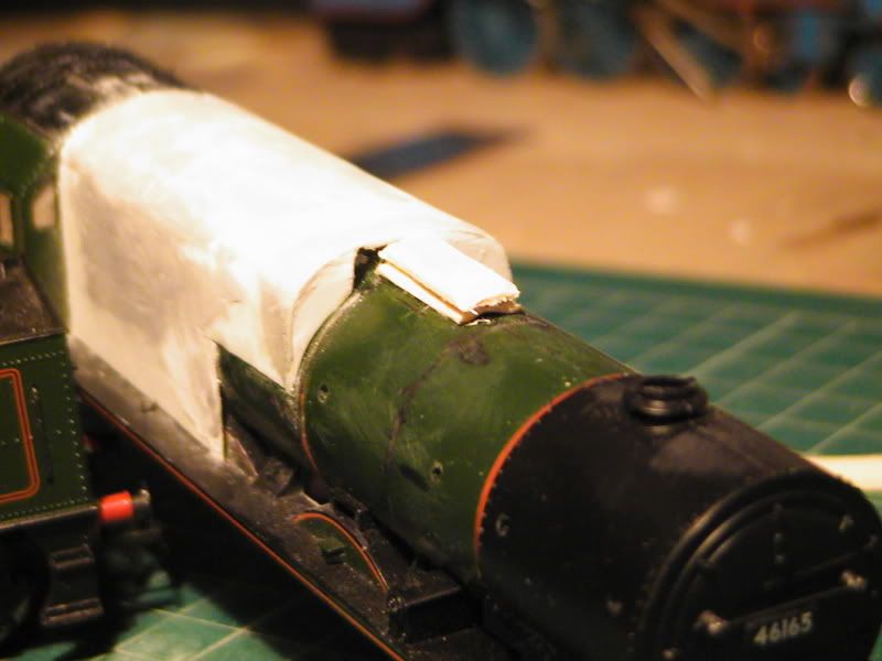
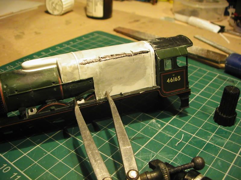
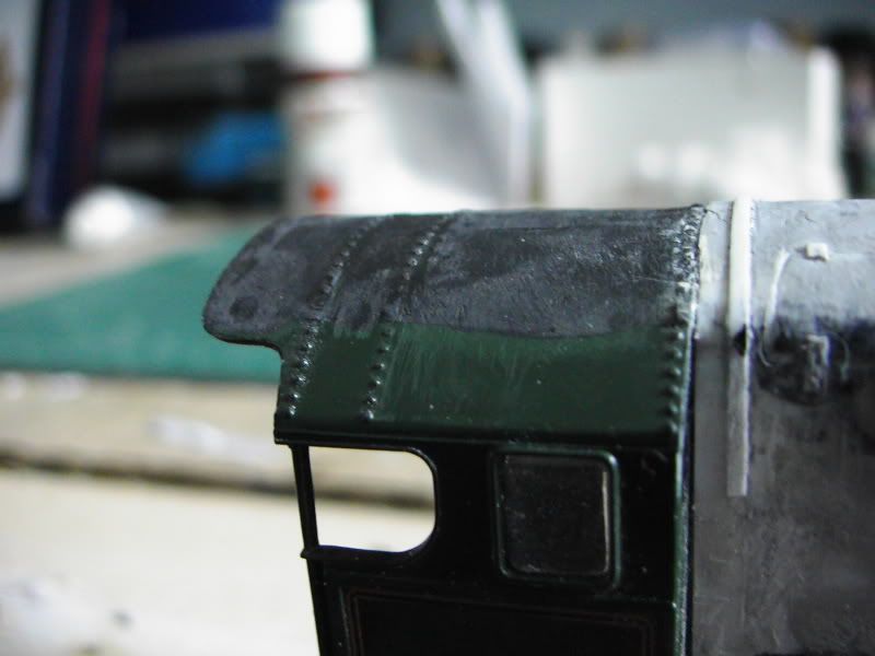
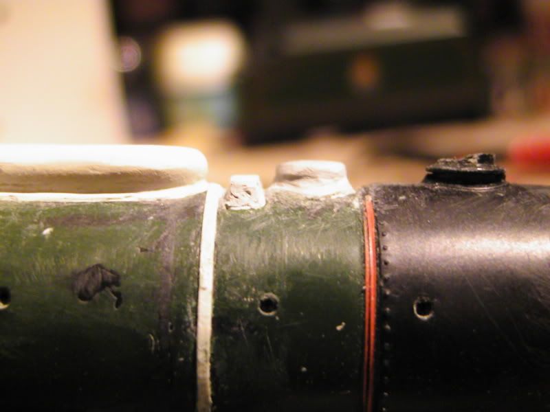
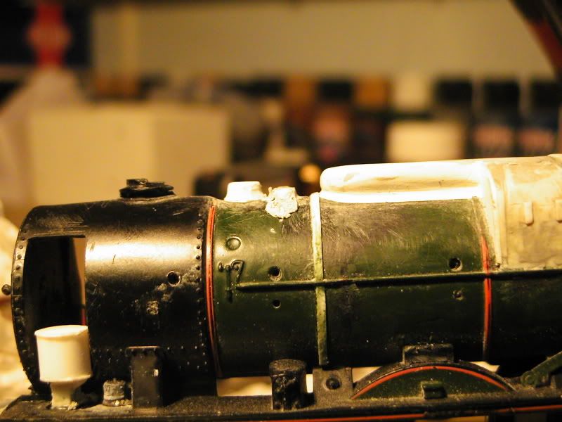
the front of the new firebox is almost done, as you can see on the left side that part is finished, to achieve that you cut a bit of plasticard roughly, as long as the curve matches the boiler your laughing.
Once glued snip the excess
then file it to get it smooth and flush like the left side, easy.
The middle is neglected because the dome is going there, so I didn't care to it much as the gap will be covered.
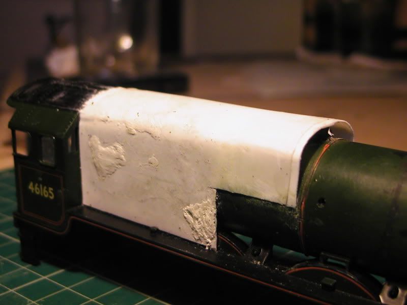
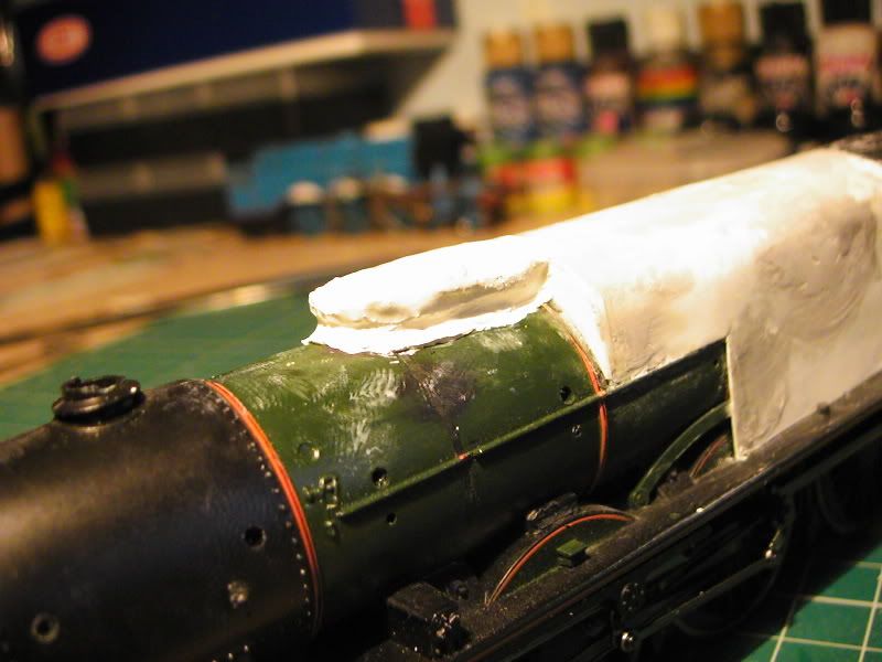
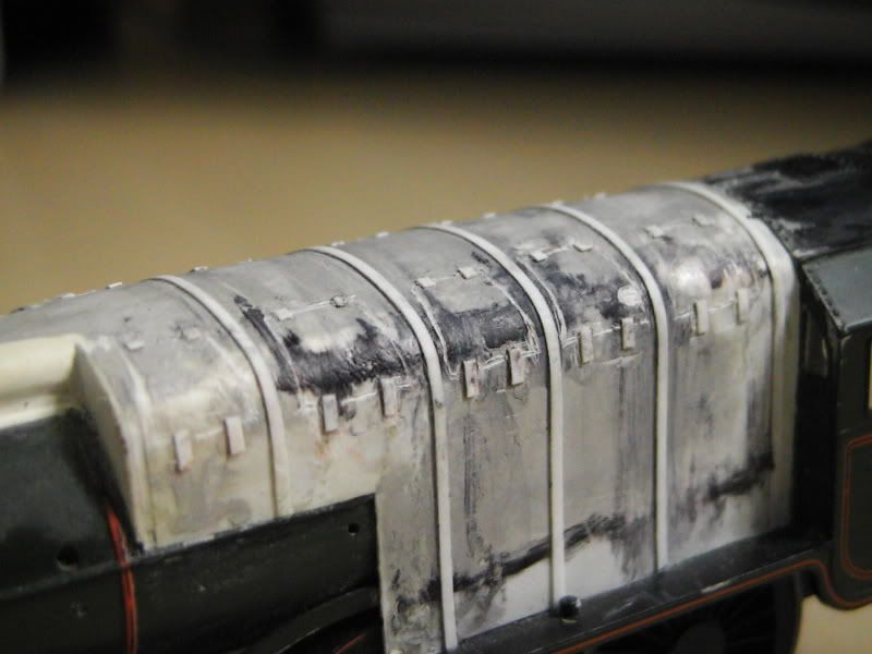
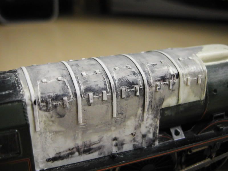
These pics also show the firebox irregularities, these are being sorted with more filler now. For this job Humbrol Model Filler is being used instead this time as it's more suited to this job over Milliput IMO. Coming along though. Next pics should be the dome modelled.
---------------
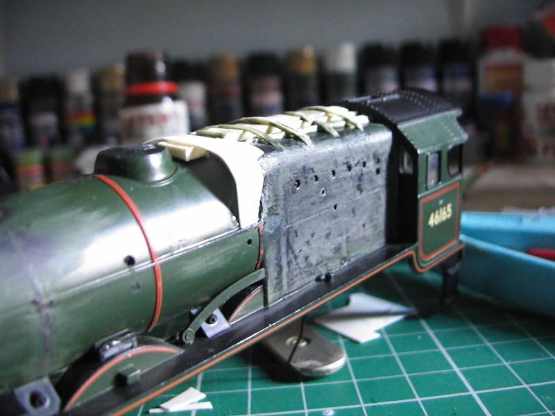
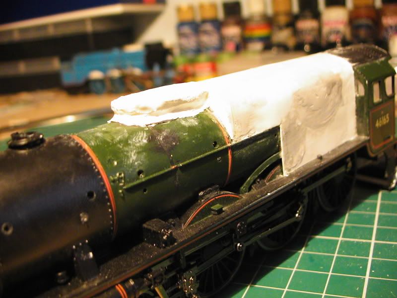
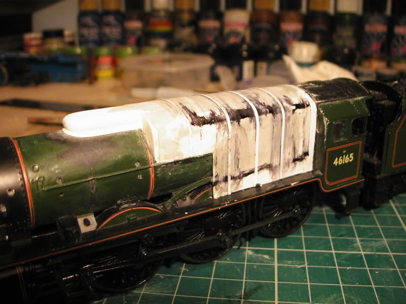
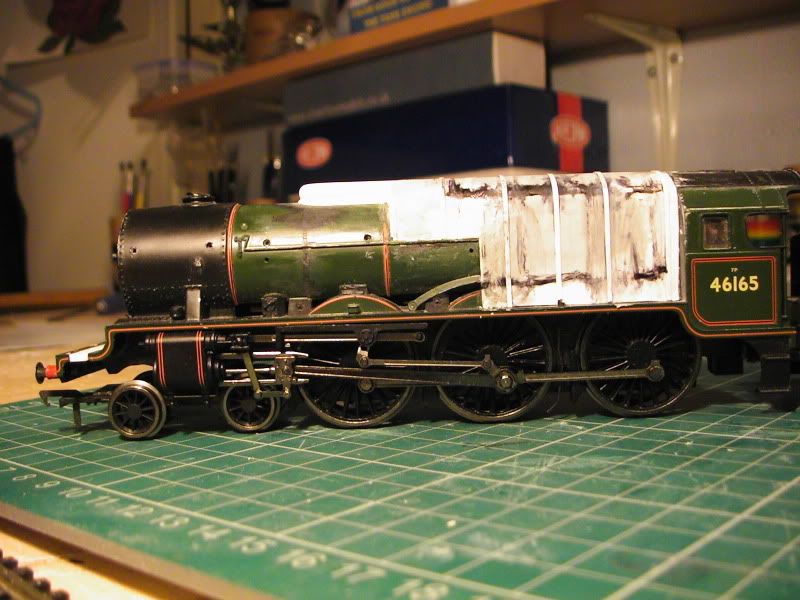
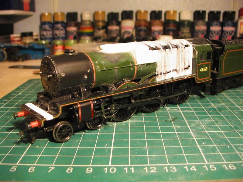
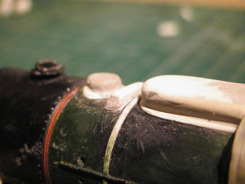
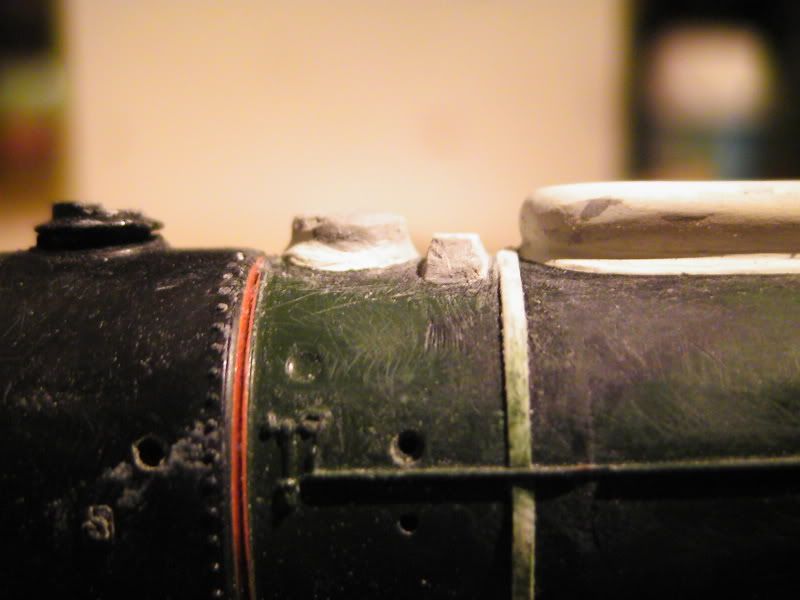
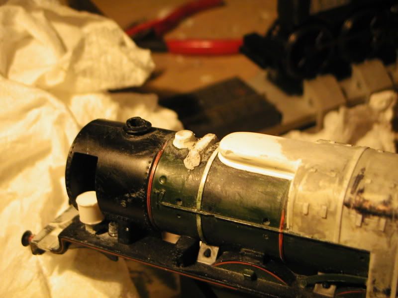
I have been working on the firebox wrap around a fair bit, filling and filing etc. Only problem is it looks like nothing has been achieved, but I asure you it has. More work still needed there though.
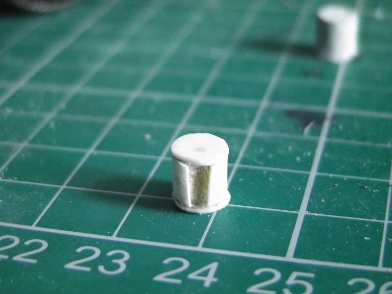
Dome has been started. Balsa wood formers cut roughly and superglued in place and my favorite on top. Milliput.
I was going to use this green bogey putty thing that Simon suggested but haven't. (I do intend getting some though)
The rough shape of the dome has been wet sculpted and I'm waiting for it to dry, then it's just a case of dry sculpting it into the correct shape. Because I have purposely made it too big means I can file back carefully into shape with more room for error. Must admit, I'm looking forward to this one, sculpting is another skill I literally found myself to be a natural at with pretty much no practice, much to the amazement of half the school and myself. I'll have to show you all one day what it was.
Anyway, progress....
-----------------------
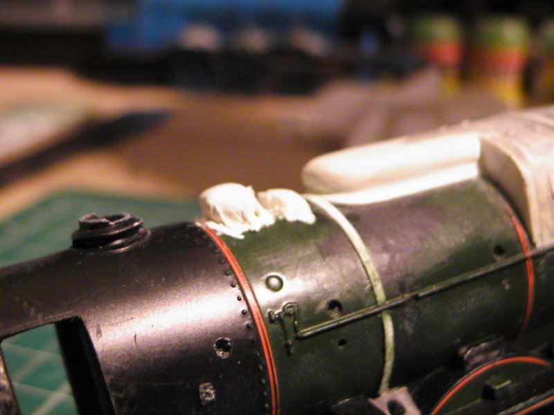
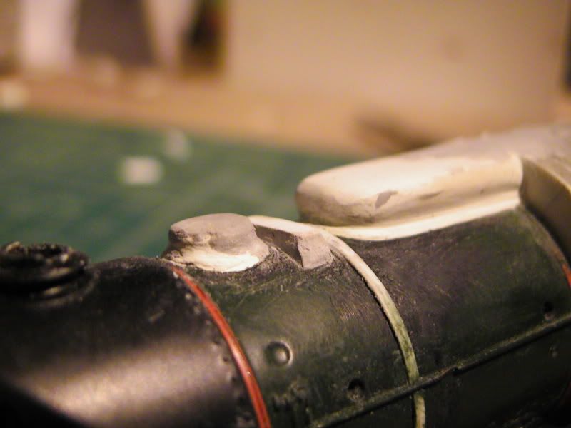
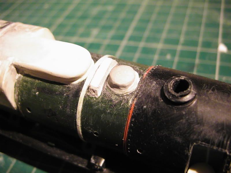
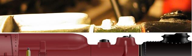
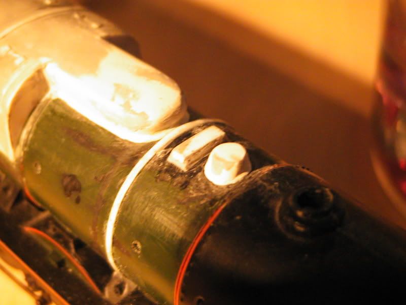
I present the DOME! It's not quite finished but it might aswell be, basically it's finished but I keep tweaking it, and it needs a tad of filler at the firebox. The firebox still needs work because it's evidently still uneven in places, but it'll be ok in the end. The dome has been sculpted out of the dried Milliput with scalpel, files and emery/glass paper stuff. It isn't perfect in profile or indeed perfectly even, but I'm pretty happy with the result, especially considering this was a 100% scratch build done by eye only. The front of the dome can be sculpted backward if need be for positioning of the boiler band. Different drawings and photographs seem to differ as to exact positioning and the base model I'm using doesn't match all of the reference material in a single configuration against other components to correctly plot the position, but we will get by.
This might have took an hour and a half, it might have took 3, I really am not sure, was in a world of my own! I remember looking at the cock at about 3 and thinking 12 was the last I saw, but I'm unsure. It's been a rather absorbing session.
I love Milliput, it's my baby
8-)
-------------------
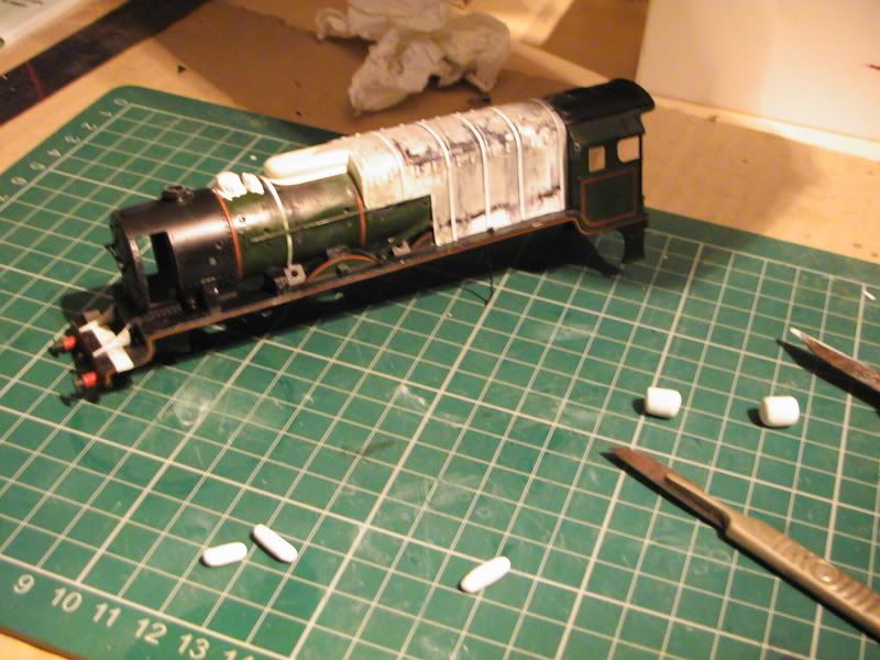
I have spent an hour or 3 modelling and am fairly pleased with what has been done.
The running plate has been extended and just needs the frame support things scratch built, the steps adding and the sides cleaned up with the lip added. Guess work using a veriety of sources.
the stripes down the side have been a fair challenge to get right; they aren't bang on but I am happy enough. I have no scale drawings to work off on paper and the base model isn't perfectly accurate as I keep saying, so I'm pleased anyway.
Plotting the 2 outermost stripes have been (like most the model) guess work and estimation based on the photographs and drawings of Fury on my computor. I think I would have atained a better result had I used thinner plasti' strip rather than 1mm wide, but I'll crack on with it anyway. Looking at multiple drawings it seems that the gap format between stripes from the cab forward is, Fat, Thin, Thin, Fat.
I've estimated this with these caliper things shown in the pictures using increments of 10, 8, 8, 10. I don't know the names of those increments as they were based on inches. The reason for this is because the increments were easier to plot the 2 standards in relation to each other. Black marker and a scratch from the calipers did the job.
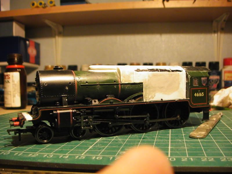
Not perfect, but I rekon a pass. Fairly happy.
8-)
-------------------------
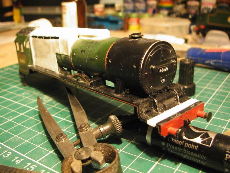
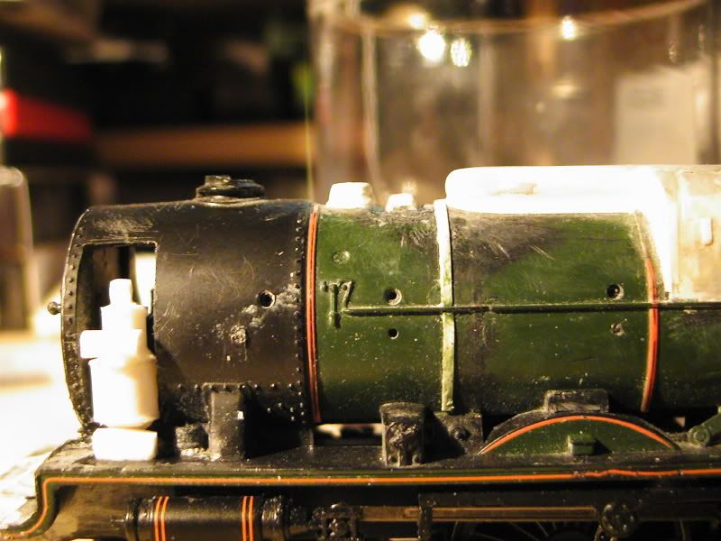
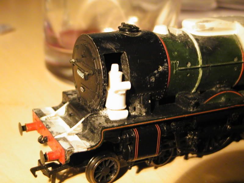
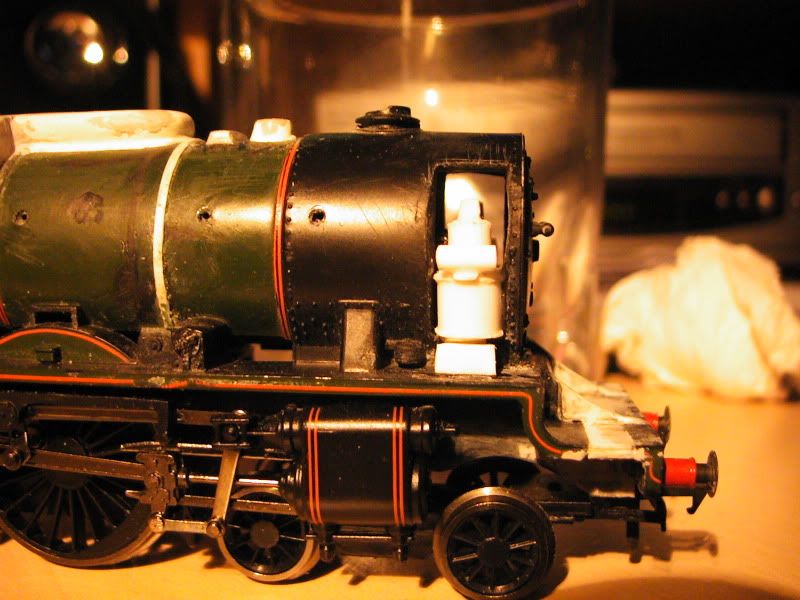
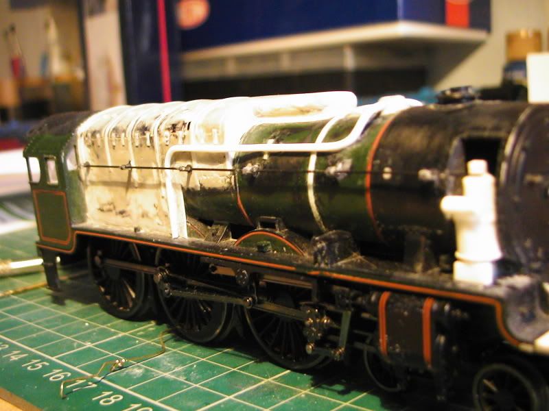
The smokebox sides have been cut out, was a real pain being roughly 5mm's thick. 
Here I have added what I think are hinges and latches for firebox access plus scored out the panel lines that are seen on some pictues.
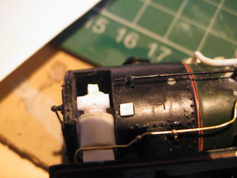
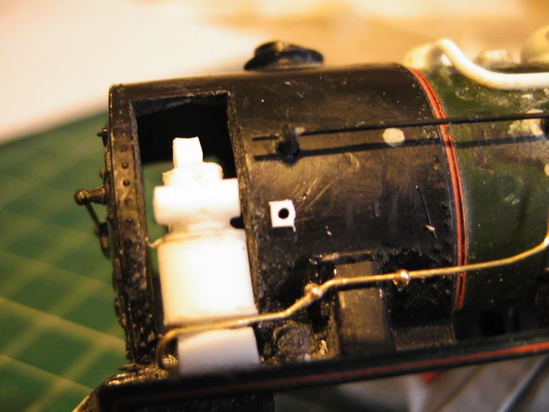
The pump has been started. I tried Milliput at 1st but it didn't look right so I have got some 6mm Balsa wood cylinder and filed it down abit, then it has been wraped in plasticard. Looks crude currently.
Pump start plonked for photographic idea of result
Cab roof has had vent and slide removed in preparation for 2 smaller ones. unsure if these rivets need removal also. Any info welcome.
Next dome has been started with Milliput and Modelfiller, need to do the smaller one after also.
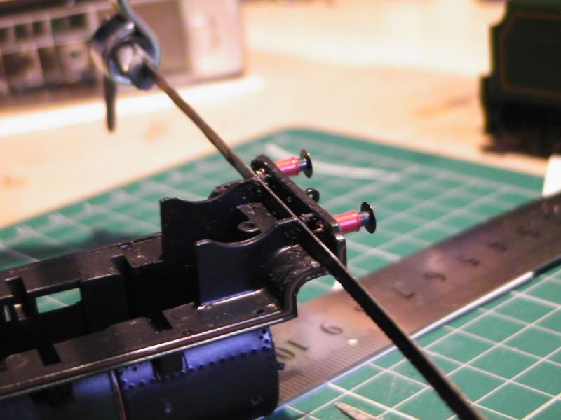
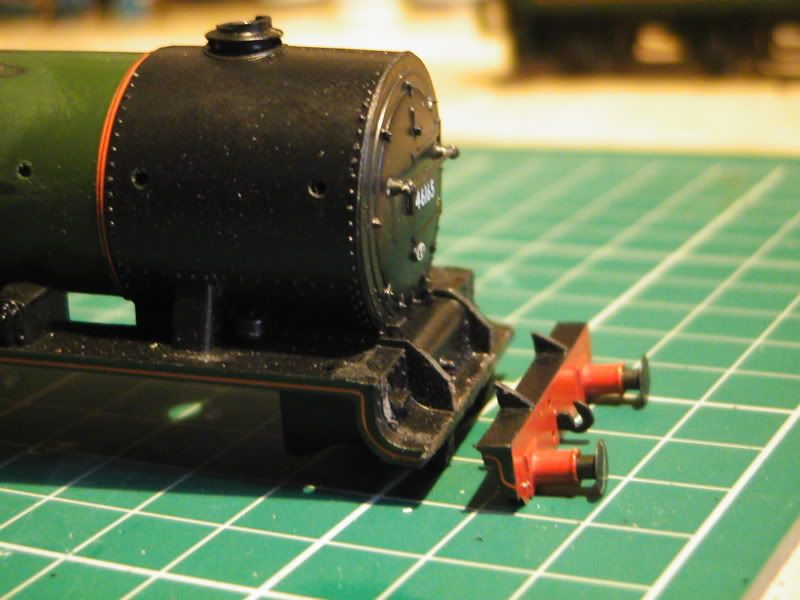
Bogey wheel arches / Frame extensions have been remodelled and..well, extended to fall in line with the plans. The gaurd irons will be added after to complete the look.
Overall impressions
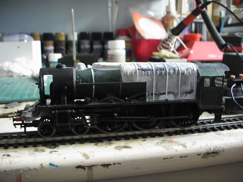
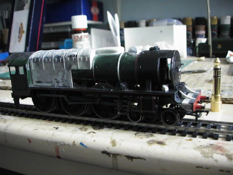
-
maybie it doesn't look that much different, but alot has been done. 
---------------------
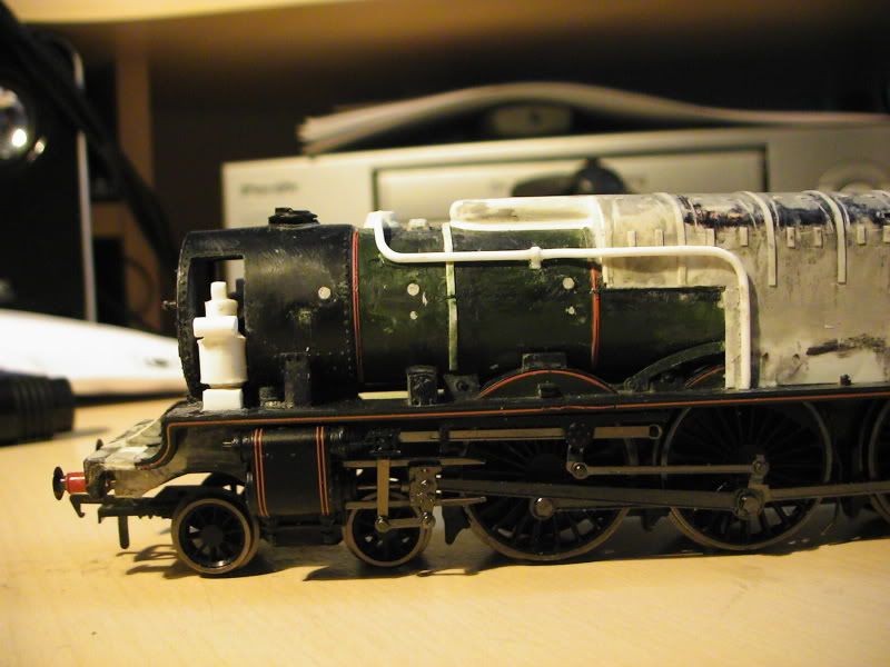
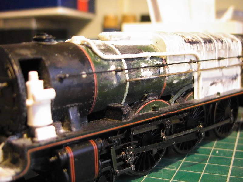
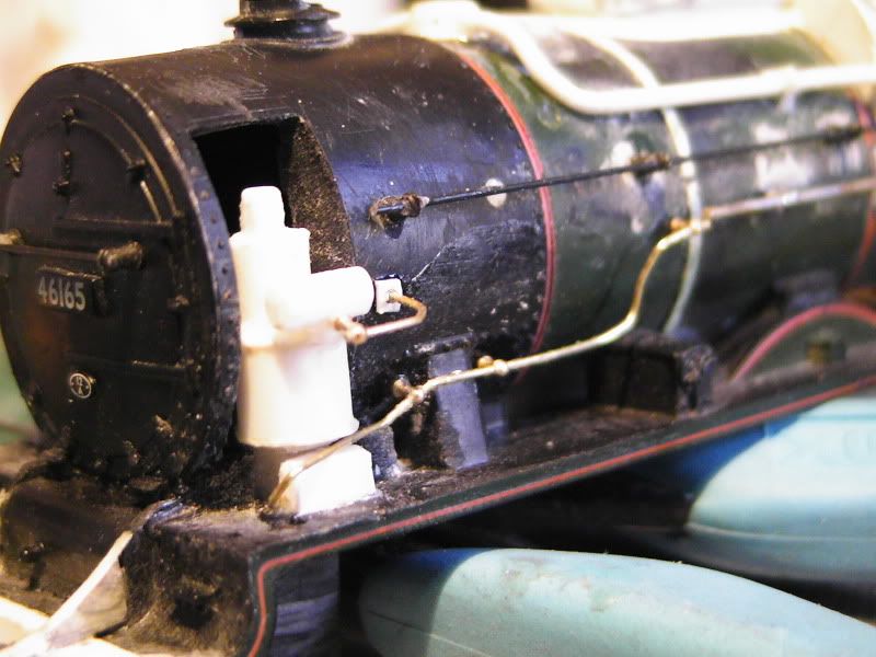
Another update. The main drum on the pump is now on it's 3rd attempt, but I'm much happier with this one. Evergreen plastic strip helped as they do cylinders. So I used 6.3mm tubing I think it was. Other than that I have about completed all 3 domes now. The 2 small ones need a mini tweak but are basically complete. They just need the smallest bit of filler and smoothening out. The straight dome was made using a bit of plastic card glued down, and then model filler around the edges - easy.
Ignore the multitude of file scratchings, it looks worse than it is. Still feels smooth.
--------------------
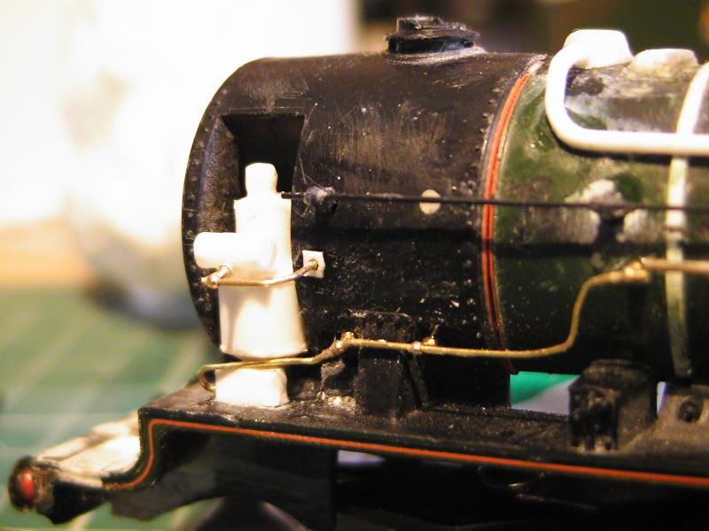
I've reduced dome sizes and dressed the long one forward abit. These pics do not show them in polished form as I haven't even sculpted them to shape yet, but just to give you an idea.
Apart from the lack of sculpting how's it looking there? Please compare it to the above posts to see changes better.
-------------------
Ding ######
Pumps are 98% complete and the domes re now also 98% complete. Apart from the usual shape tweaks consider them finished.
Long mini dome complete, the other small one is almost done but looks rather like a fairy cake here. Will be sorted.
Yeah, getting there.
--------------------
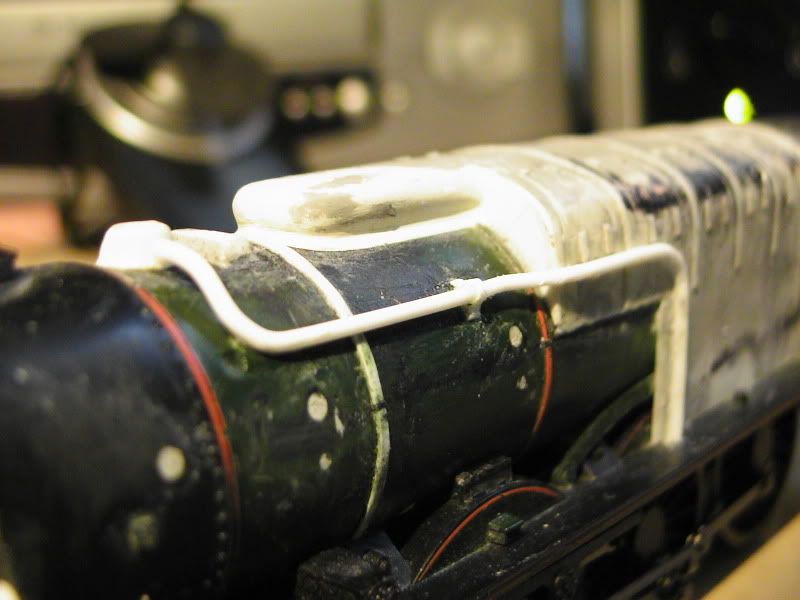
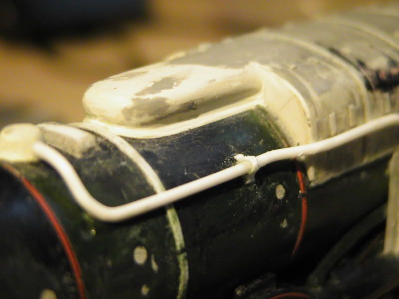
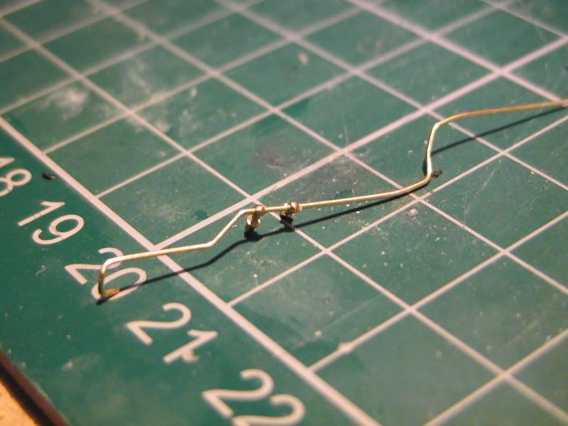
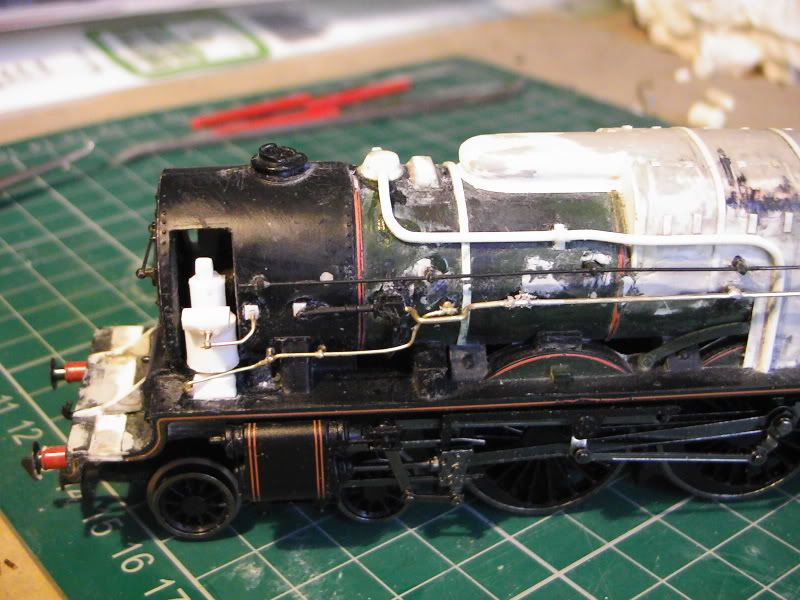
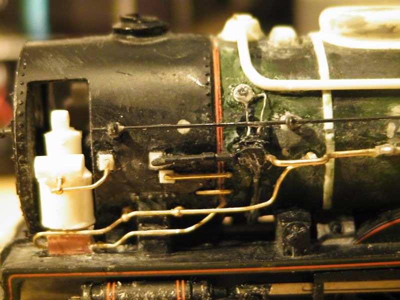
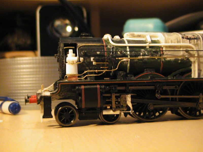
My Evergreen pipes have arrived. First one has been bent to shape and glued on, bracket scratch built as per the drawings. Abit crude, but I'm rather happy with the impression it gives. It's just abit of scrap strip glued to the boiler, the pipe glued to that, and then a longer strip glued on top and bent around it, rather like the real Omega Brackets (or whatever they are called).
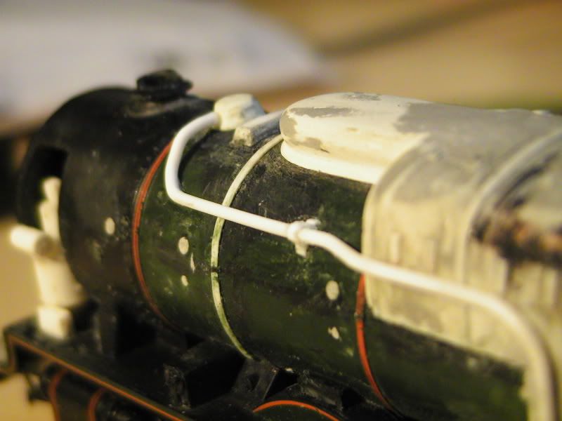
------------------
Super Update!
Bet your all in a FURY with me having no update for over a month. Hahaha, No? No, I didn't find it funny either, I'm just typing crap while the pictures uplaod. Anyway, erm, yes, update...
Haven't modelled much in the past month due to a multitude of personal problems that I'm overwhelmed by, but never mind that for now. been modelling this morning and authough things arn't bang on I'm happy enough.
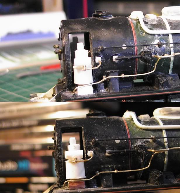
Original side hand rails are added but with the hand rail pillars moved and also another rail in 7mm brass, I didn't have any pillars for these so I cheated by drilling the hole out until they snaped leaving just a cresent, then soldering a blob to represent the ball of the pillar! Easy.
I hope you can see these shots of the box things at the side of the smoke box saddle, I drilled a hole in them for the brass wires.
3 pillars were slid onto this 0.45mm brass wire. Perfect for hand rails and I think it is a standard size. It's what I always use anyway and the pillars rarely need reaming out to fit. Brass wire bent into shape and pillars added.
Wire fittted, was a swine to locate, bit of a fight.
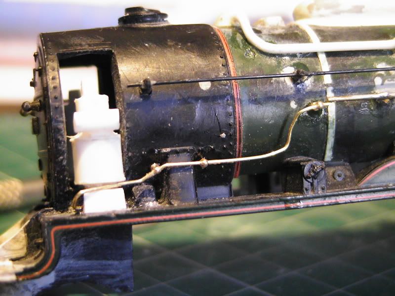
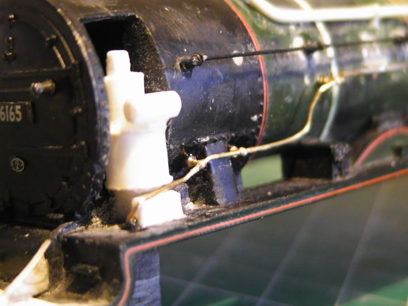
On the horizontal drum on top of the pump you may just be able to see I have drilled a hole. I then made a plastic square.
The square was trimmed and drilled to take another brass wire/pipe.
Pipe fitted with one hand rail pillar. I had to rebend it slightly to match the profile so these pis arn't consistant.
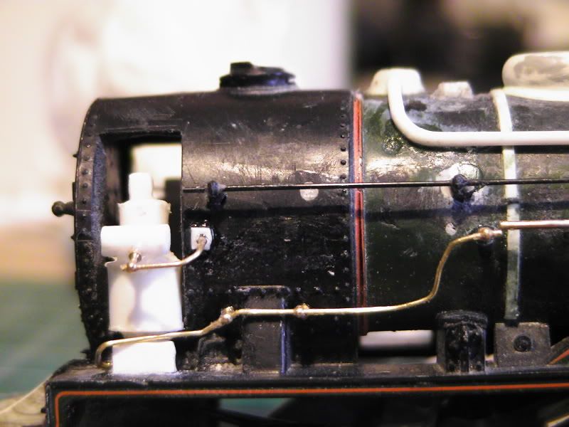
This urm..thing needed a tweak so I drilled a hole in to accept more wire, this time 7mm.
Which was then fitted onto the boiler side with a bit of shaped brass that links to the main brass pipe. Another small square has been added to the smokebox side.
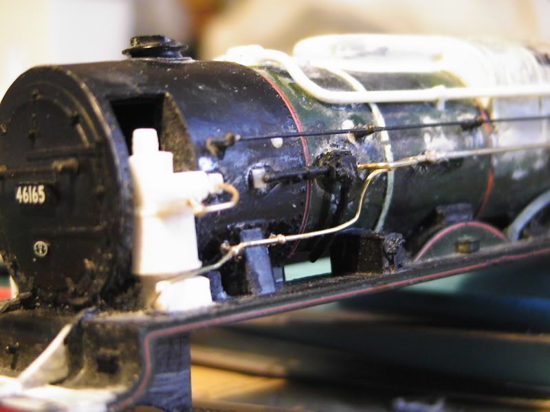
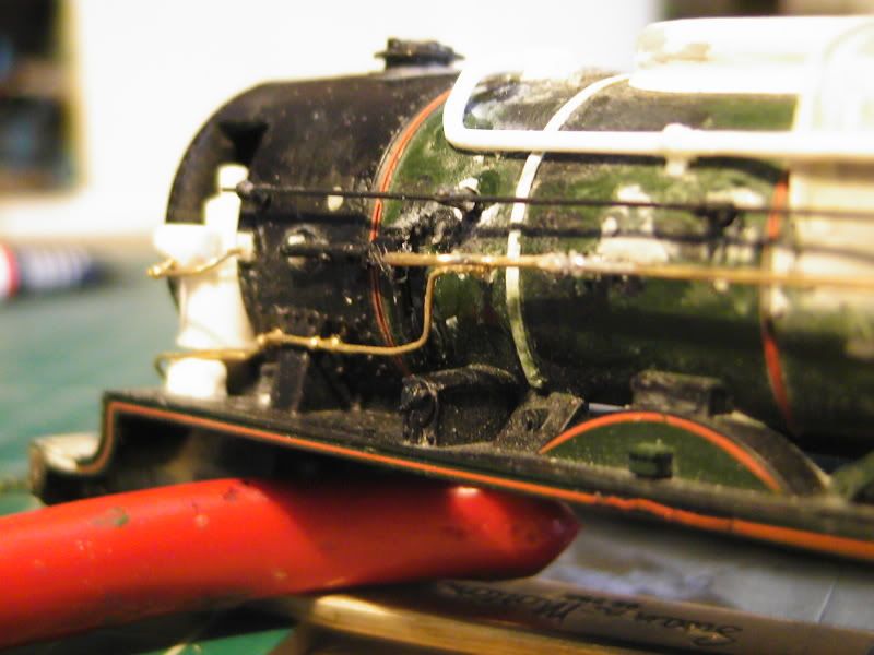
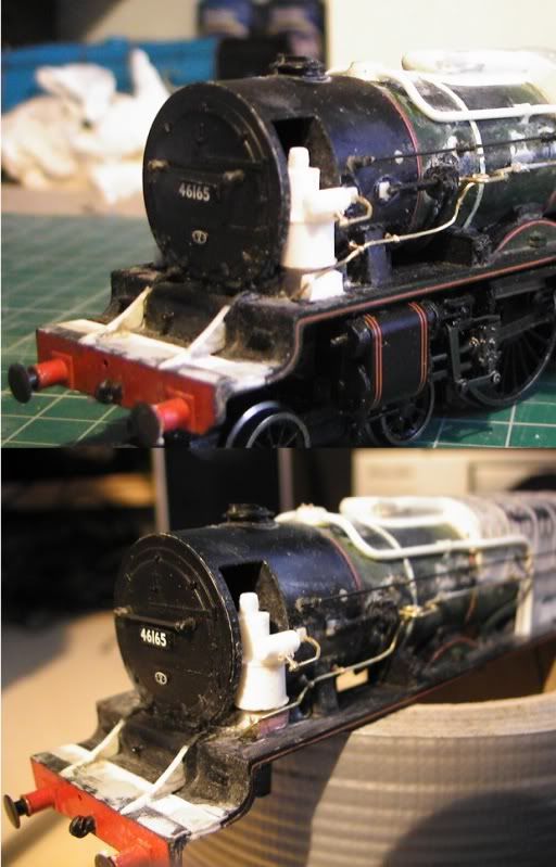
Angles arn't 100% perfect but good enough. Components and bends are a tad overscale I'd say. You may also notice the whole thing is badly gummed up with glue, but I know from previous experience not to worry as I can clean it up pretty well prior to painting. Also need rivets and more detail as it isn't all added yet.
Final impressions thus far.
8-)
--------------------
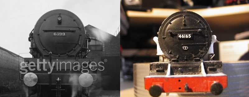
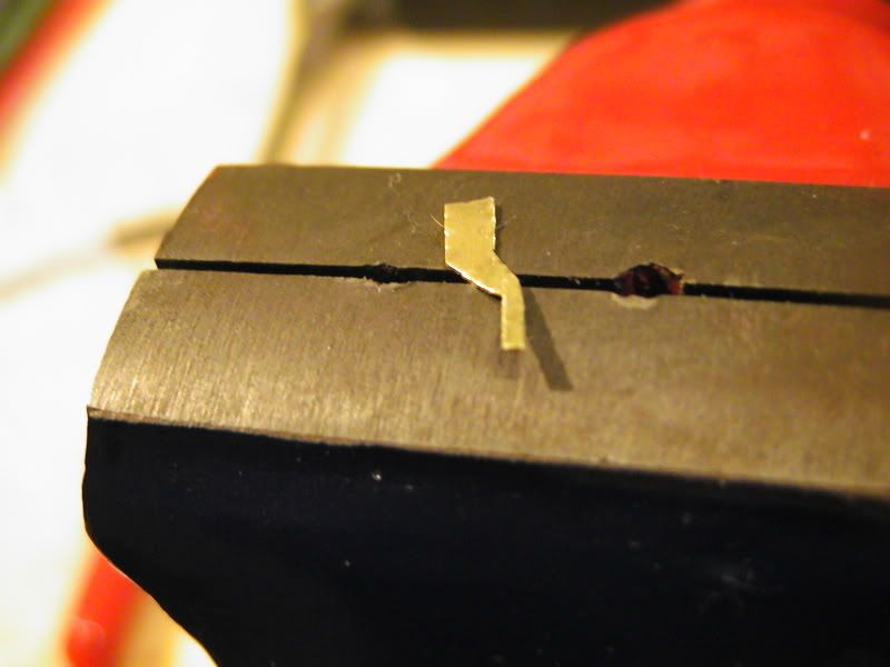
Another mini update linked to the one above. The plastic box that is under the main pump drum was positioned about 1.5-2mm's too close to the running plate edge. So I have bent the wire away and removed the boxes, used a slitting disk to destroy the plastic and then fitted the boxes closer inside. This time I used a bit of PCB instead as the thickness was about perfect. Also a comparison of the prototype to see accuracy. Compare.
-
EDIT: Another update!
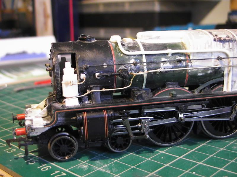
More pipe work added. Please forgive the glue, will be cleaned up later.
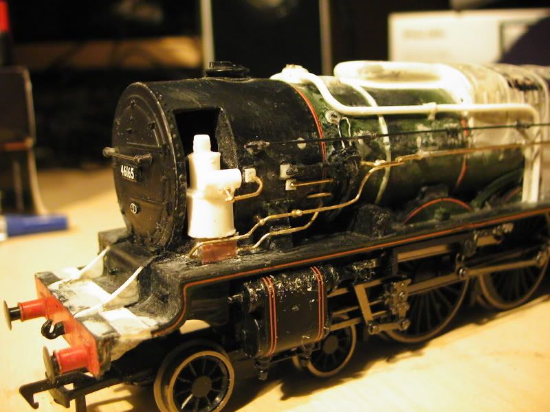
Other than 1 pipe and a few rivets, this side is about done. 5 amp fuse wire was used for the baby pipes. They are mounted on a plasticard disc I made with a trimmed plastic handrail pillar popped into a pre drilled hole.

--------------------
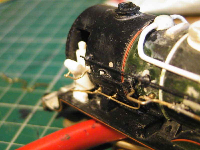
Update! And this time it's interesting.
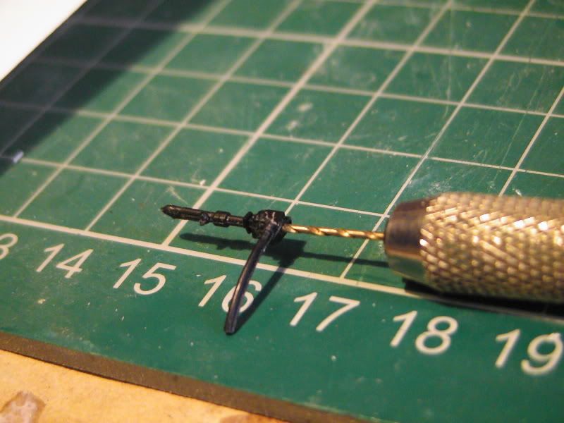
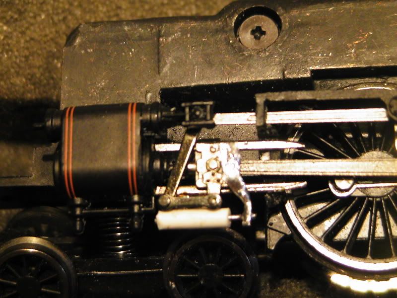
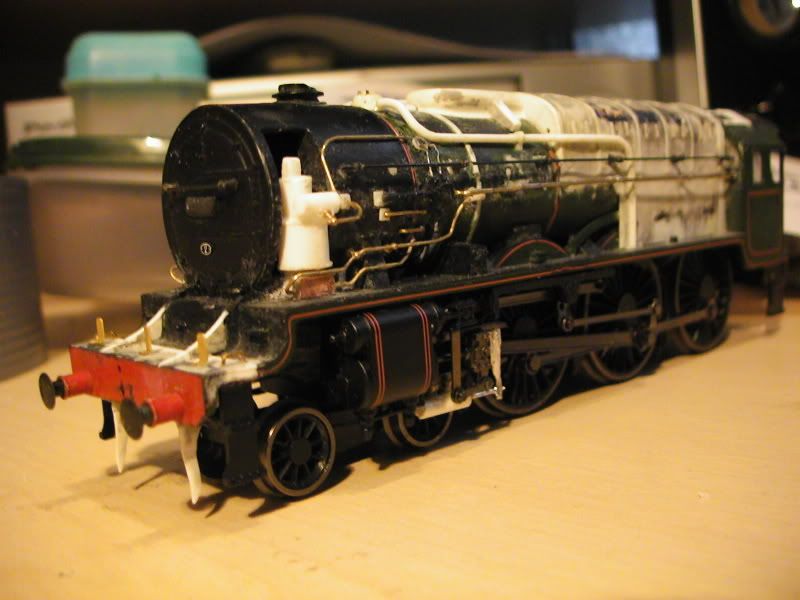
I drilled a hole in some plastic tube, and then drilled a fatter hole in also. Then I had to make some thin brackets and bobs to bash mock valve gear additions. The valve gear the model comes with has a special coating on so that needed scraping off to adhere to the solder and flux. Being a material less suited to what I have I had the iron on 450c to actually make it all work. But it does so I'm happy, see what you think. Brass rod formed the piston. The best thing about this is, it actually works with zero problems.
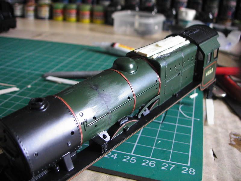
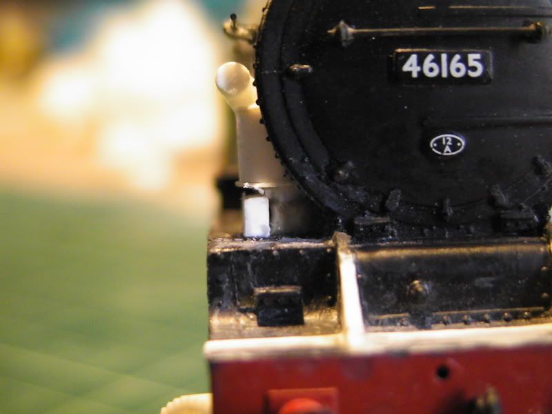
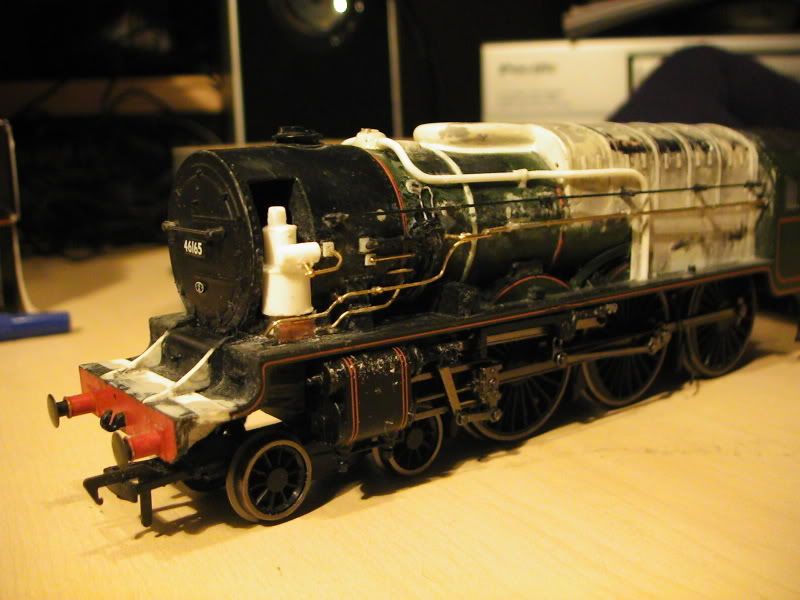
Also I have added a 'lump' to the main dome, added the lamp irons, steps and gaurd irons. The lamps may be trimed a tad though but unsure yet.
IN
OUT
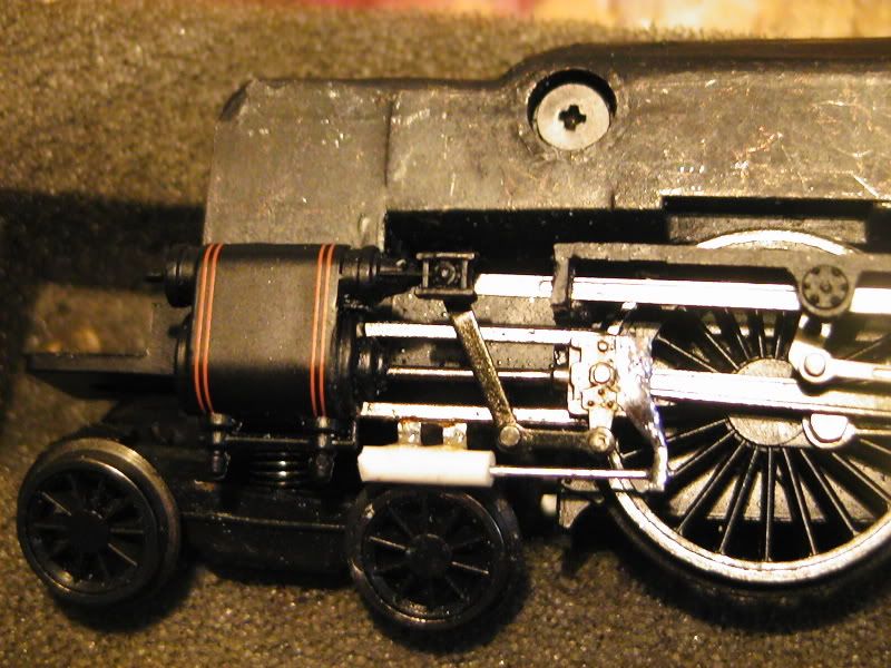
There is alot of excess solder on that as you can see, so I might file it away later.
Impressions
Jobs to do:
Solder tender together.
Clean body work up.
Prime it all.
Add the rivet transfers (on top of the primer).
Paint it.
Line it.
Add front coupling and brake/vacuum pipe.
Add cylinder drain pipes.
-
I'm still naffed off with the incorrect drum height but I think I'll leave that for now, 'MIGHT' do it one day if I can get the heart to, but if I do that will be after the competition/meet up.
8-)
------------------------
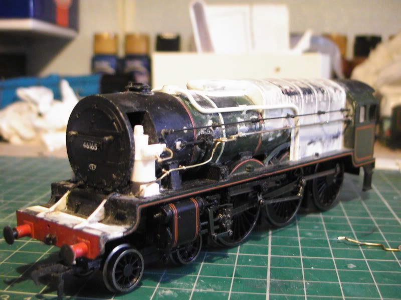
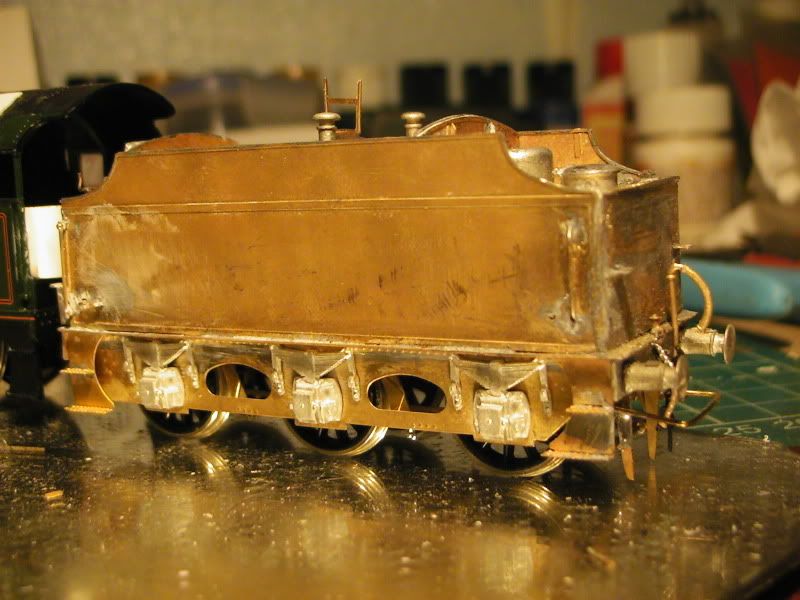
Last set of pictures before completion.
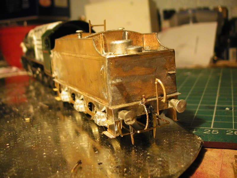
The tender I actually made a pigs ear of. Gordon's (My 1st brass soldering kit) went together rather nicely. James's (my 2nd) I hardly read the instructions and that went together fine also. This one however went together badly, reason? I didn't look at the instructions much! But unlike before I made some stupid mistakes......complacency. As a result I soldered the tender sides on the wrong way, this means I had to fill the drilled holes out and then drill new holes on the opposite side. This wasn't a problem but because the insides of the sides are different it caused complications and the back peice wouldn't go on properly and was, as an estimate, about 1-1.5mm's too far back! I fixed this by going evil with a tough file and eating it away. The back peice then went on better but was too high requiring me to chop it at the top and then add a brass rod to reinstate the 'lp'. The gaps were filled with thick solder blobs and then filed/sculpted to shape, consequently the dimensions are abit out in places but the good thing is it isn't that obvious. I'm happy with the repair bash.
The other problem was the plate you stand on was soldered in the wrong place, I couldn't unsolder it because it was stuck fast so I had to force it out with pliers. This cockled the tender sides badly.
Filling and filing solder just made it worse so I have had to use Humbrol Model Filler, looks ok now. (didn't photograph that bit!)
The moral of the story? Over confidance and complacency can get you in trouble, read the instructions. Still, I got some great bash practice in and I'm really happy with the result, it didn't beat me. 
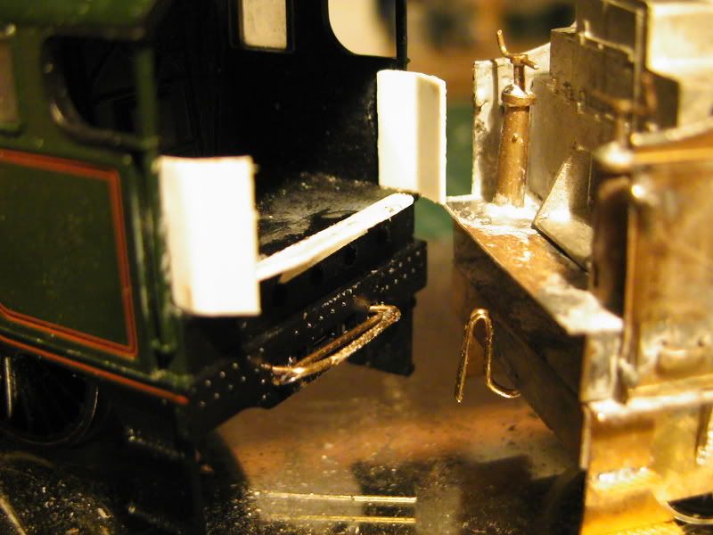
Loco and tender connector is crude but it's my preferable way of joining it. Literally a crude loop and hook. Gordon rolls nicely like this with no problem. Also the fall plate and doors are abit of scrap plastic card. Everything in this paragraph looks rough and I haven't bothered making it neat, this is because once it's painted it's hard to tell, especially as it's all 'in' the cab area. I don't mind the lack of perfection but if it looks naff after paint then I'll tweak it - easy.
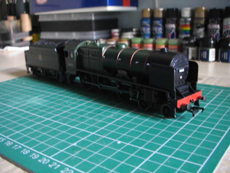
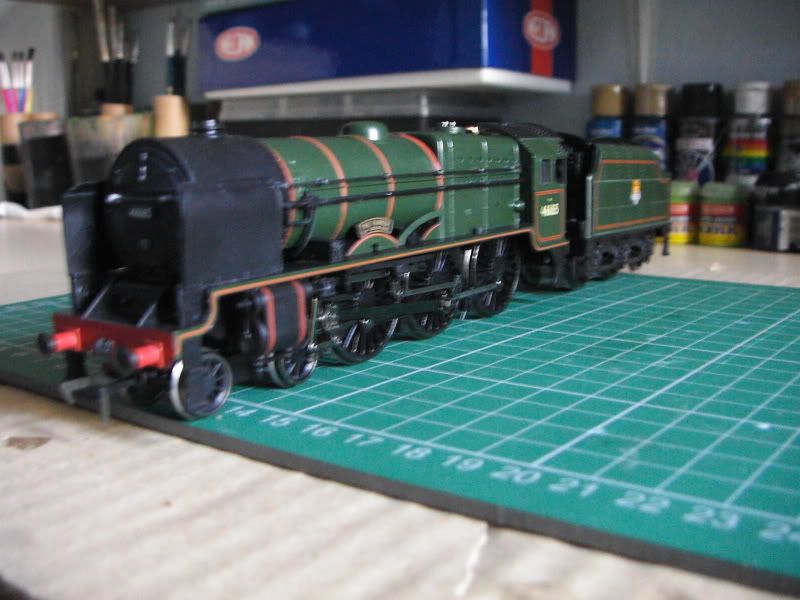
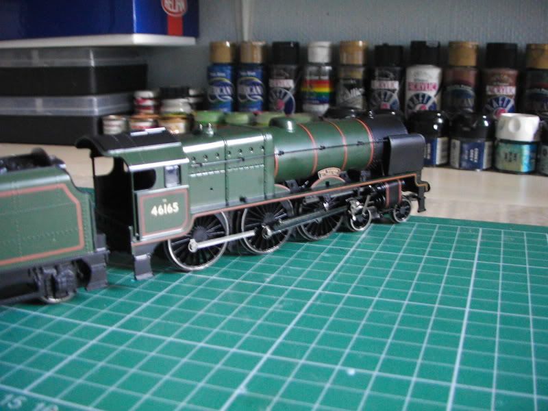
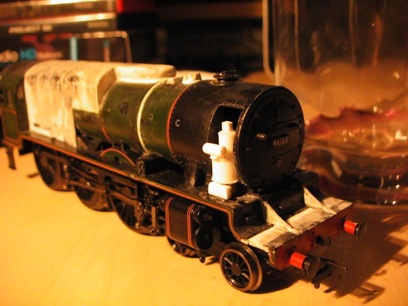
Ok, pictures below. The only things left are to add the whistle, rivets, front coupling and brake pipe, paint and line. That literally is it, can't wait.
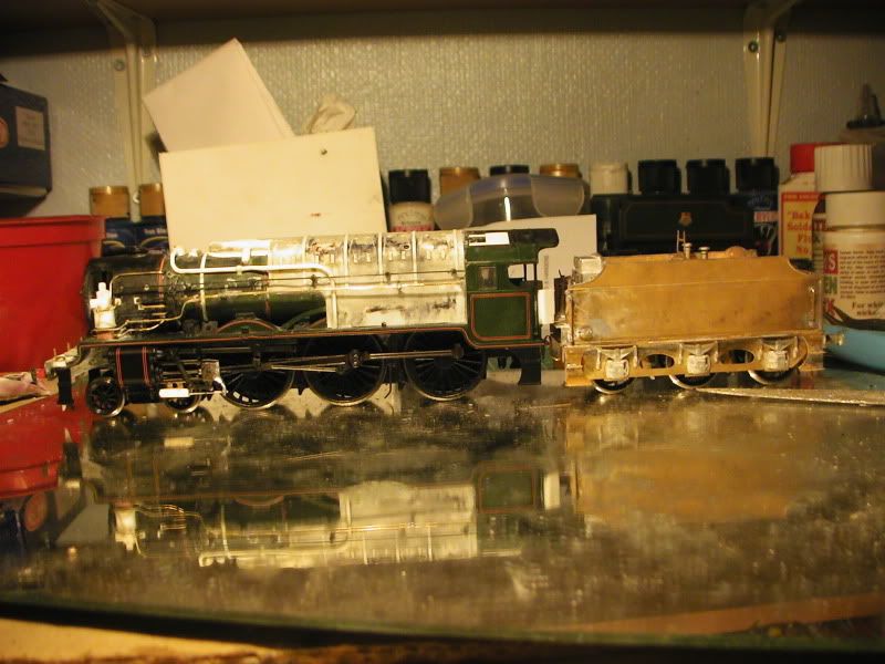
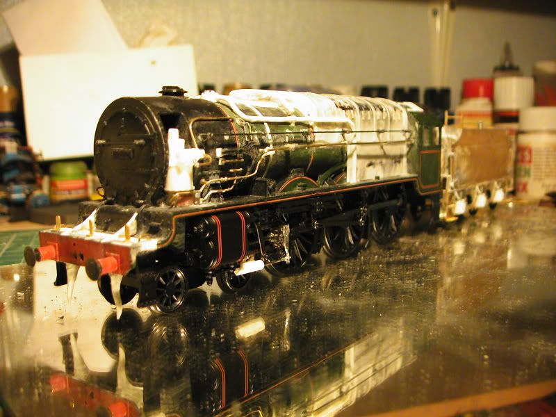
That's it, other pics are the completed pics.
-
 4
4

5 Comments
Recommended Comments
Create an account or sign in to comment
You need to be a member in order to leave a comment
Create an account
Sign up for a new account in our community. It's easy!
Register a new accountSign in
Already have an account? Sign in here.
Sign In Now