Jump to content
 

Flight of the bumblebee


Mikkel

3,925 views

blog-0291417001399562800.jpgI’m building a traverser of sorts for the fiddle yard of my little goods depot layout. From an engineering perspective it’s a bit dodgy - yet somehow it works, so I’ve dubbed it the bumblebee.


My original plan was to have a fiddle yard with points, but as space is becoming an issue I decided to go for a traverser instead. Trouble is, my engineering skills are equal to those of the common earthworm.


So I’ve been putting it off, until I came across some bits and pieces in the local DIY and acted on impulse. What has developed is best seen as an experiment!


Img_2792.jpg


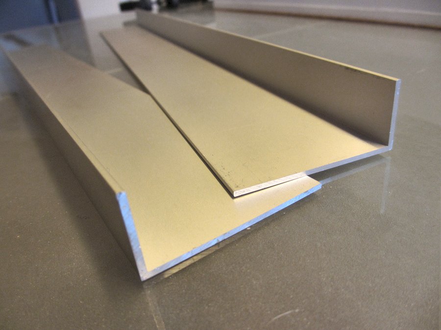
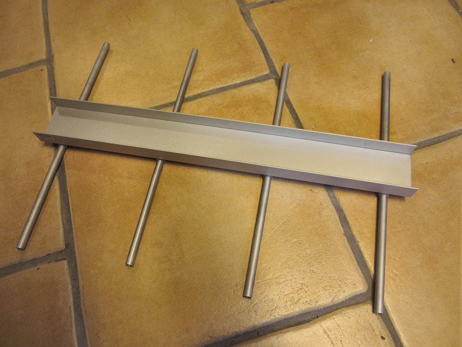
Two aluminimum angles from the local DIY.


Img_2796.jpg


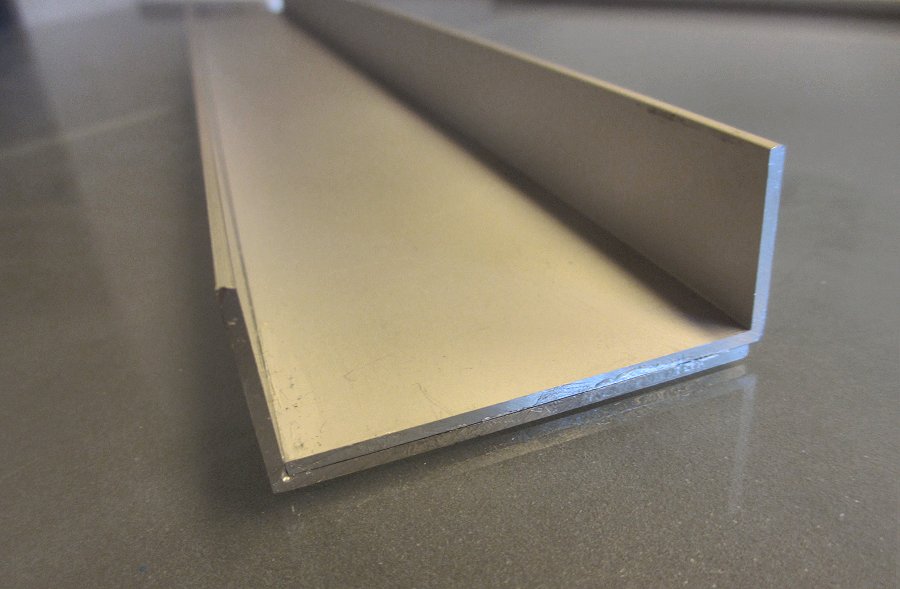
Cobbled together, they make up a sturdy cassette.


Img_2797.jpg


Aluminium tube, cut into sections and fitted underneath the cassette.


Img_2822.jpg


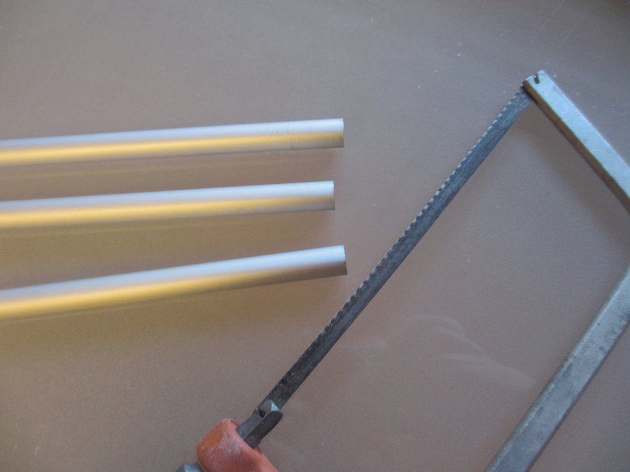
Thinner aluminimum tube. Also available in brass - possibly better, but costly and heavy.


Img_2831.jpg


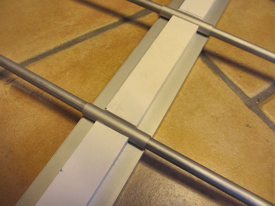
Thin tubes slide into thicker tubes…


Img_2832.jpg


…resulting in this beast: A traverser-style sliding cassette.


Img_2827.jpg


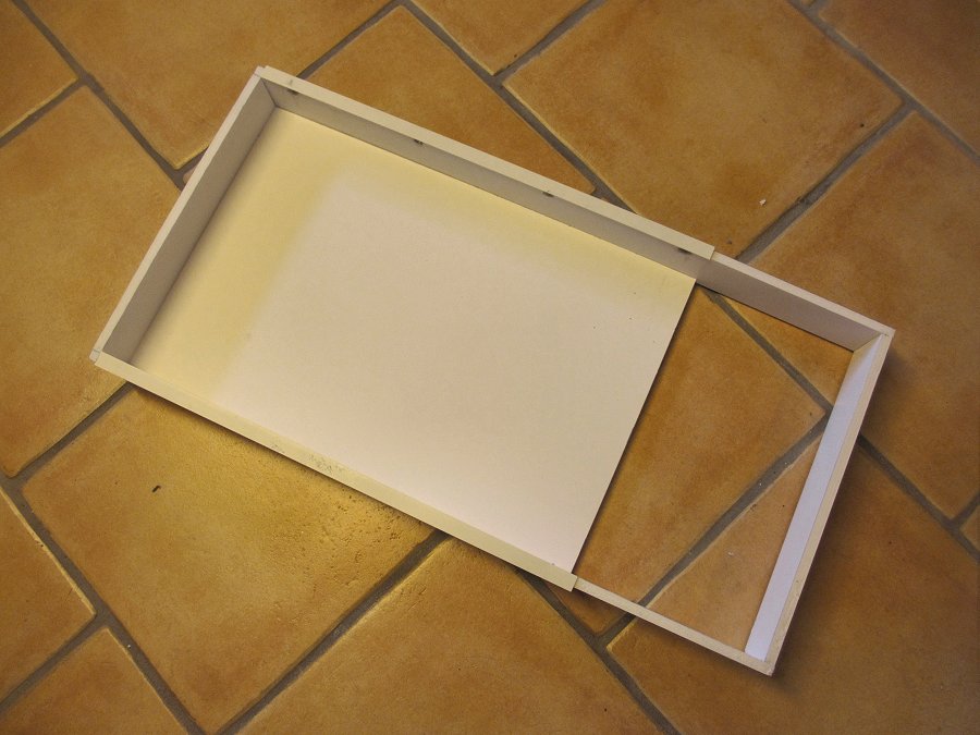
Frame built from 10mm foamboard. Ahem!


Img_2847.jpg


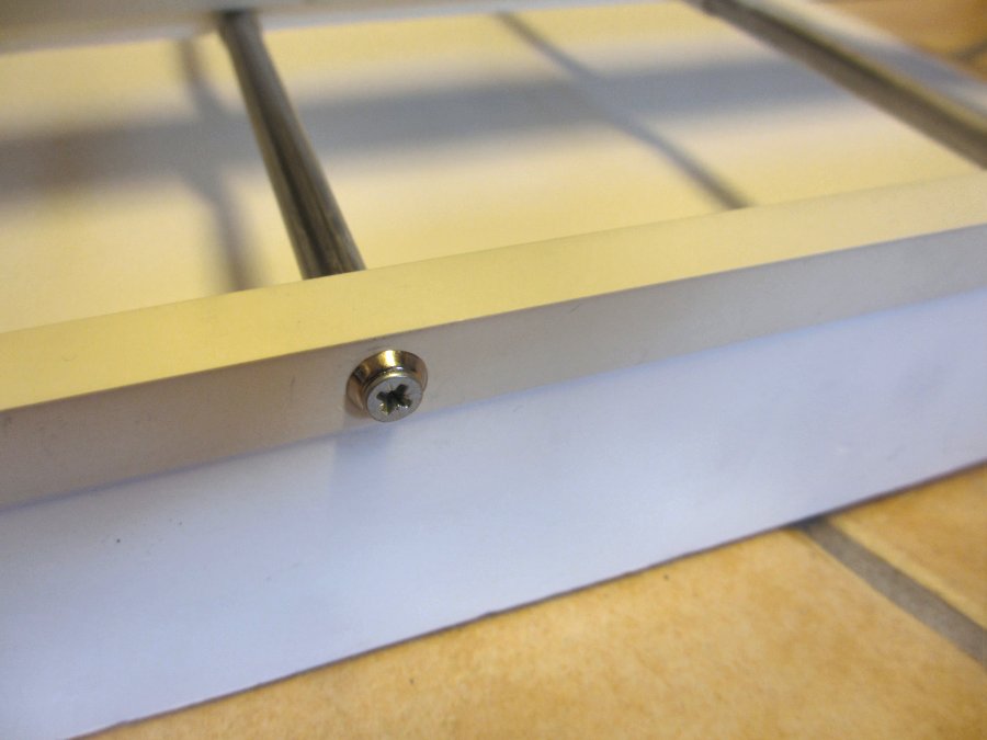
Plastic angle and screws, used to secure tubes to frame. Rawplugs inside the tubes.


Img_2844.jpg


Everything fitted together. Looks OK but does it work? At first I wasn’t happy. There was a bit too much friction when sliding the cassette. The foamboard was still nice and square though, so I must have not got the tubes perfectly aligned. With four tubes there is very little room for inaccuracy.


Img_2842.jpg


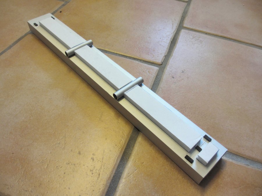
So I removed the two outermost “guide tubes” from the cassette, and fitted foam pads in their place (track underlay). The foam slides on top of the outermost tubes, meaning there is still support at the ends.


Img_2986.jpg


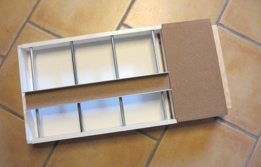
With this arrangement, the cassette slides smoothly. I have added a cork underlay and am now waiting for fresh supplies of Sprat & Winkle uncoupling magnets, which will be installed in the cork-base on the right hand side so I can use delayed action S&W couplers. The wooden “lip” connects the traverser to the layout through a piggy-back arrangement.


Testing suggests that so far this contraption works surprisingly well. The bumblebee flies. The big question is for how long! There’s clearly a risk that the foamboard will warp or get twisted from heavy use. If that happens, I’ll try a Mk2 version with a wood frame.

  • Like 11
  • Craftsmanship/clever 2

30 Comments


Recommended Comments


Despite continuing to play down your engineering skills, your inventiveness and application is definitely superior to your every-day oligochaeta. However, I'm desperately disappointed that we didn't see the traverser built in time-lapse video to the strains of Rimsky-Korsakov  ;)

Link to comment

I think you created a nice and light solution.

The clear description how you made it is useful for anyone who will build a similar traverse. Can you tell something about the size.

I will keep him in mind.

Link to comment

Hi Mikkel,


That looks the business - very nice!


There is nothing ramshackle about that and indeed nothing permanent that can't be transferred to the wooden frame Mk 2 version in time!


All the best,


Castle

Link to comment

Great idea Mikkel.


I have recently been thinking of ways to lay out my storage yard which will be beneath Hemyock and you have now given me something else to think about, it looks a lot simpler than some of the ideas going through my mind.


Jim

Link to comment
  • RMweb Gold

Despite continuing to play down your engineering skills, your inventiveness and application is definitely superior to your every-day oligochaeta. However, I'm desperately disappointed that we didn't see the traverser built in time-lapse video to the strains of Rimsky-Korsakov  ;)


Had to look up oligochaeta, word of the day!


To me, "sound engineering" is about building things to last beyond the foreseeable future, being highly precise, and trying to foresee and accommodate risk. None of those things apply to this traverser, so I was just trying to warn people about that :-)


Rimsky-Korsakov looks like he requires a bit of study too. There goes the evening :-)

Link to comment
  • RMweb Gold

I think you created a nice and light solution.

The clear description how you made it is useful for anyone who will build a similar traverse. Can you tell something about the size.

I will keep him in mind.


Hi Job, the whole frame is 70 x 35 cms. The cassette is 50 cm, which is enough for a tank loco and 5 (steam era) wagons.


 It is very light indeed (except for the cassette). However this can also be a problem: If there is no measure to keep it in place, the whole structure will inevitably move when the cassette slides back and forth. To avoid this, I am going to use some home-made height adjusters with rubber "soles" that I have made for the baseboard for "The sidings". These are quite effective in keeping everything firmly in place. Will make a post on that later.

Link to comment
  • RMweb Gold

I'm a great believer in the KISS principle of engineering (Keep it simple stupid!). I'd say your solution is very elegant and if like the bumble bee, shouldn't work but does, so much the better!


The mark 1 bumble bee works just fine and I reckon your fiddle yard will do just the same!


Dave

Link to comment
  • RMweb Gold

Hi Mikkel,


That looks the business - very nice!


There is nothing ramshackle about that and indeed nothing permanent that can't be transferred to the wooden frame Mk 2 version in time!


All the best,


Castle


Hi Castle, thanks, I think the basic idea may have some potential that can be developed further with a bit more thought and experimenting.


I initially thought about drawer sliders, but those available in our local DIY store did not seem very stable, and were set up in a way that would have required more room at the front. No doubt better ones are available, as has been proven many times by others, but this alternative seemed straightforward and worth a shot.

Link to comment
  • RMweb Gold

Jolly intelegent earth worm!


Julie


Hi Julie, come to think of it, most of us aren't nearly as smart as the worms in our garden - they can build a huge underground network without anything collapsing! :-)

Link to comment
  • RMweb Gold

I'm a great believer in the KISS principle of engineering (Keep it simple stupid!). I'd say your solution is very elegant and if like the bumble bee, shouldn't work but does, so much the better!


The mark 1 bumble bee works just fine and I reckon your fiddle yard will do just the same!


Dave


Thanks for the encouraging words, Dave. It's mostly the foamboard I worry about - that might have been a bridge too far!  But keeping my fingers crossed....

Link to comment

Interesting traverser that one, but I must admit I'm quite happy with much simpler manual systems.


I, like you thought about drawer runners but was not happy about the amount of movement in some that would occur with quite a large board especially when extended (open position), looking at your method above makes me think I should get some linear bearings on steel rods supported at both ends and give that a go, pity both me and a toolmaker friend have retired as we could have got hold of both of them quite easily when at work.


I look forward to seeing how your traverser progresses.

Link to comment
  • RMweb Gold

Great ingenuity Mikkel. A brilliant piece of engineering. ;)


Almost the Table Football of traversers! 


Hopefully we can see some more of your modelling soon as well.


Cheers,


Mark

Link to comment
  • RMweb Gold

Looks good to me.


Hi Paul, well it certainly saves space, compared to the "actual" fiddle yard that I originally had in mind. The idea is to operate the layout as a shunting puzzle, so the traverser will be intensively used.

Link to comment
  • RMweb Gold
 

Interesting traverser that one, but I must admit I'm quite happy with much simpler manual systems.


I, like you thought about drawer runners but was not happy about the amount of movement in some that would occur with quite a large board especially when extended (open position), looking at your method above makes me think I should get some linear bearings on steel rods supported at both ends and give that a go, pity both me and a toolmaker friend have retired as we could have got hold of both of them quite easily when at work.


I look forward to seeing how your traverser progresses.


Just looked up linear bearings. Some very interesting options there, thanks for pointing that out! Some look like they could be used almost directly without mods (like these or these).


For good quality drawer runners, I see that Station Rd Baseboards have some (no connection).

Link to comment
  • RMweb Gold

Great ingenuity Mikkel. A brilliant piece of engineering. ;)


Almost the Table Football of traversers! 


Hopefully we can see some more of your modelling soon as well.


Cheers,


Mark


Thanks Mark, yes Brunel has nothing on me ;-) The similarity to Table Football also struck me, now that would be an unusual modification!


Modelling is a bit disjointed at the moment, too many projects on the go at the same time. That always slows down progress, I find.

Link to comment

Hi Mikkel,


Impressive improvisation as always sir...


Just one technical comment, to stop accidental racking, as you have no bracing other than the panels, would 4 simple corner frame stiffeners not be a simple solution?


And will this traverser be operated by an immaculately detailed set of 4mm Edwardian navvies? :-D


Best wishes


Matt

Link to comment

Mikkel,


What a really elegant solution to the sliding traverser problem!!  The only thing I would be a little concerned about is whether the aluminium over aluminium will continue to slide well over time.  But obviously only time will tell.  The only reason I say that is that I would have thought different materials (say stainless/silver steel steel rods with brass tubes) might wear better - I do however have absolutely NO engineering experience to justify that statement only gut instinct!


I look forward to Mk II where you have added a leadscrew to finely control the for and aft movement ;-)


Really useful post though and something to put on file for the "next project" !!


Ian

Link to comment
  • RMweb Premium

Fantastic and very neat workmanship, Mikkel.

I entirely agree with other comments here - you do great injustice to your engineering skills. The use of the tube guides instead of wooden rails has greatly reduced friction and is a flash of genius. Certainly be a method I will be using for a future fiddle yard for Cheslyn. Love the preciseness of it - it looks cool too!


PS - a little loco lube on the middle guides should help.

Link to comment
  • RMweb Gold

Hi Mikkel,


Impressive improvisation as always sir...


Just one technical comment, to stop accidental racking, as you have no bracing other than the panels, would 4 simple corner frame stiffeners not be a simple solution?


And will this traverser be operated by an immaculately detailed set of 4mm Edwardian navvies? :-D


Best wishes


Matt


Hi Matt, thanks, good point about corner protection. I did actually consider child proofing corner guards - but perhaps that would be improvising just for the sake of improvisation :-)  I can probably get something simple and cheap in the DIY to serve the same purpose better.


No navvies for the operation I'm afraid, just plain old hand operation.

Link to comment
  • RMweb Gold

Mikkel,


What a really elegant solution to the sliding traverser problem!!  The only thing I would be a little concerned about is whether the aluminium over aluminium will continue to slide well over time.  But obviously only time will tell.  The only reason I say that is that I would have thought different materials (say stainless/silver steel steel rods with brass tubes) might wear better - I do however have absolutely NO engineering experience to justify that statement only gut instinct!


I look forward to Mk II where you have added a leadscrew to finely control the for and aft movement ;-)


Really useful post though and something to put on file for the "next project" !!


Ian


Hi Ian, you could be right about the aluminimum on aluminium issue. When I had the initial problem with friction I tried with a bit of lubricant (as per Pasternoster Row's comment below) - perhaps I should do that again to create a thin layer between the tubes...


Using brass tubes for the inner tube is certainly an option, although it adds a lot to the weight. The brass is stiffer too, although I would say that the alu tube is surprisingly rigid.


Leadscrew, eh? I had to look up what that means in Danish - I'm on a steep learning curve here :-) 

Link to comment
  • RMweb Gold

Fantastic and very neat workmanship, Mikkel.

I entirely agree with other comments here - you do great injustice to your engineering skills. The use of the tube guides instead of wooden rails has greatly reduced friction and is a flash of genius. Certainly be a method I will be using for a future fiddle yard for Cheslyn. Love the preciseness of it - it looks cool too!


PS - a little loco lube on the middle guides should help.


Thanks Mike, it would be interesting to see what you can make of it.


Not sure how it would work with multiple tracks on the deck. Getting the innermost traverser track to serve the outermost layout track could present some practical problems, as far as I can see. 


Ps: just went back to your pics of Cheslyn, haven't seen them for a while - that station building really is superb!

Link to comment

Hi Job, the whole frame is 70 x 35 cms. The cassette is 50 cm, which is enough for a tank loco and 5 (steam era) wagons.


 It is very light indeed (except for the cassette). However this can also be a problem: If there is no measure to keep it in place, the whole structure will inevitably move when the cassette slides back and forth. To avoid this, I am going to use some home-made height adjusters with rubber "soles" that I have made for the baseboard for "The sidings". These are quite effective in keeping everything firmly in place. Will make a post on that later.


Mikkel, thanks for the information.

Link to comment

Create an account or sign in to comment

You need to be a member in order to leave a comment

Create an account

Sign up for a new account in our community. It's easy!

Register a new account

Sign in

Already have an account? Sign in here.

Sign In Now

×
×
  • Create New...