Jump to content
 
  • entries
    15
  • comments
    54
  • views
    22,999

Falling Behind: A Leader Story (Pt1)


Grasslands

2,385 views

blog-0994848001359484874.jpgI tried to think of a good Leader pun, but ‘falling behind’ works as an inverse analogy.


36001


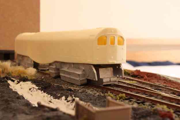
The picture above shows one of my favourite locomotives: 36001, Bulleid’s Leader; the monstrous experimental steam engine that looked like a diesel. Leader was constructed in 1948 and ran for a brief 1½ year period (from 1949 to 1950). ‘Ran’, of course, might not be the best word for Leader’s trial runs, as she was prone to failure and was often towed back to Brighton Works.


Leader was fitted with various experimental design features including: a chain drive; a fully enclosed boiler; and a cab at either end. She was also fitted with an off-centre boiler (very strange). The fire box was located near the centre of the loco and must have been a terrible environment for a fireman.

I always found something fascinating about this loco and urged my parents to buy me a book on the subject. When I left home, this book was one of the first things that I ‘acquired’ from my parents house.


The Model


There is a resin kit available of Leader, made by Golden Arrow Productions, which I got for my Birthday in 2008. After purchasing a load of Bulleid Q1 wheels (expensive), I set to work planning out the look of the model. The Golden Arrow Productions mould is good, but I thought it a shame that it missed out some of the more prominent panel lines, so I stencilled the panel lines out onto the moulding and scored these onto the resin with a modelling knife.


I was also not to keen on the shape of the windows, which I felt didn’t quite capture the look of the prototype. Following the guidance of a topic on converting the Golden Arrow Leader on RMweb, I decided to widen the windows and slightly change their shape.


img_1626lr.jpg?w=625&h=416


img_2214lr.jpg?w=625&h=468


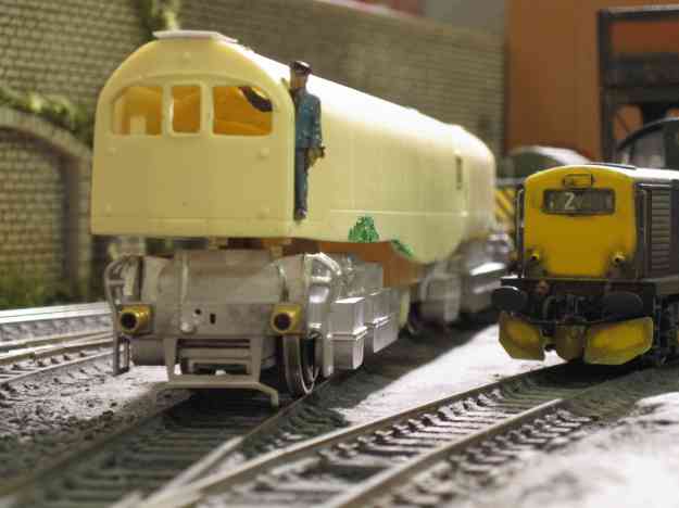
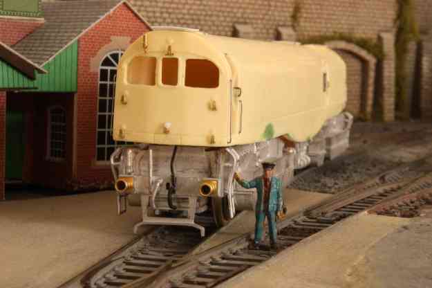
The white metal chassis blocks are lovely mouldings for this model, and when built they really give you an idea of how big this engine really was (an idea of scale kindly provided by driver Bob in the pictures above and below). It might not be the best engine to build if you have a layout with low tunnel mouths, as it really is a beast. The real thing towered over most water tanks, making it difficult to top it up with water.


img_0124lr.jpg?w=625&h=416


Liveries


Livery-wise there are a surprising number of options for an engine that ran for such a short period of time. Leader carried prime grey with a large British Railways ‘cycling lion’ emblem (only on one side) for a very short period. The British Railways emblem was quickly removed and the engine was lined out (along its panels), but remained in grey.

I have never cared much for either livery and I instead opted for the livery (well… not really a livery) present in the only colour picture that exists of Leader. At this stage it was being repainted and appears to be a very silvery grey. This was the first image of Leader that caught my eye, many years ago and this was what I wanted on my model.

More about the build next time….


visit grasslandsmodels.wordpress.com for further projects

  • Like 9

10 Comments


Recommended Comments

Hi Grasslands,


What about all over black as a livery? There is a photo in one of Kevin Robertson's books showing the Leader in this colour in the workshop.


Could be fun at shows, the derision and then whipping out the picture to say "told you so!"


I rather like the grey too I have to say - gives it that prototype / experimental look!


All the best,


Castle

Link to comment

The off-centre boiler isn't that strange, as a good many American Shay locomotives were built this way to allow room for the crankshafts, etc.

Link to comment
The off-centre boiler isn't that strange, as a good many American Shay locomotives were built this way to allow room for the crankshafts, etc.


It would be great to see some examples. I think in Leader's case it didn't help it's running qualities. It suffered quite a few bearing failures.

Link to comment

Hi Grasslands, I too have taken the plunge and bought a leader.

have started cleaning the castings up and giving the body the once over to ‘iron out’ a couple of moulded details a didn’t like the look of but I was wondering what you did with the chassis? On the diagram included it shows an improved drive idea and wondered how would you get round the centre float axle? I’m new to the white metal castings and was looking for a little help.

  • Like 1
Link to comment

I modified the original instructions (partly by mistake) and I installed one DS10 motor on each bogie and linked them together so they could pick up off both bogies. I retained the floating middle axle, and the model doesn't pick up of the floating axle (but I might change that). 


I used an Ian Rice design of pick up based around some lengths of brass wire with little bits of copper cladding soldered on them which slip behind the wheels. 


It hasn't run in a while, and I still have some work to do, but the tests went well and it runs fine. 

  • Like 1
Link to comment

That sounds great, how did you get the middle axle to float? Did you solder the 1/8” axle bushes to the main white metal block? Could you maybe elaborate on what it means by floating axle for me? Surely if you solder the axle bushes to the main block then it’s not floating. 

sorry this is all new to me

Edited by SouthernWay
Link to comment
44 minutes ago, SouthernWay said:

That sounds great, how did you get the middle axle to float? Did you solder the 1/8” axle bushes to the main white metal block? Could you maybe elaborate on what it means by floating axle for me? Surely if you solder the axle bushes to the main block then it’s not floating. 

sorry this is all new to me

Sure! 


I have the central axle floating in the slot in the chassis and I didn't add any brushes to that axle. All it means by floating is that is effectively loose to follow the rest of the wheels. The slots inside the chassis means there isn't too much excess play. I was okay with this arrangement as it is similar to how the Heljan Westerns are set up.


I added bushes for the other axles though. And yes, I soldered those, but I used a low heat solder for white metal and a variable temperature soldering iron (set to a low temperature). I got all that stuff from Gaugemaster.

  • Like 1
Link to comment

That’s very helpful thank you.

so just for clarity, with the central axle, did you put axle bushes on it or do you just drop the axle in the hole and allow gravity and it’s own weight to hold it in place?

i was just wondering, if I could extend the drive shaft coming off of the motor one end then do you think I could drive all three axles??

Edited by SouthernWay
Link to comment

My central axles are just dropped into the holes with no brushes.


You could plausibly drive all wheels but you would need a gearbox that can run across all three axles. The one that I have for my DS10 motor is just one ratio gear (fixed to the leading axle) and joins to the worm on the motor shaft. You could investigate the gear boxes at High Level Kits, but there isn't loads of room inside the chassis. 

  • Like 1
Link to comment

Create an account or sign in to comment

You need to be a member in order to leave a comment

Create an account

Sign up for a new account in our community. It's easy!

Register a new account

Sign in

Already have an account? Sign in here.

Sign In Now
×
×
  • Create New...