

My Deltic Sound Project
.thumb.jpg.60c53fcbcaa34017b05b8919d1a9e6d2.jpg)
Entry posted by Silver Sidelines
2,315 views
Continuing the north east theme I have invested in a Bachmann Deltic of the two tone green variety. I had to cancel an order on eBay when a quick check revealed that the Deltic Preservation Society still had ‘The Green Howards’ in stock (and many more Bachmann models) at very competitive prices, frequently below the cost of second hand items on that well known auction site.
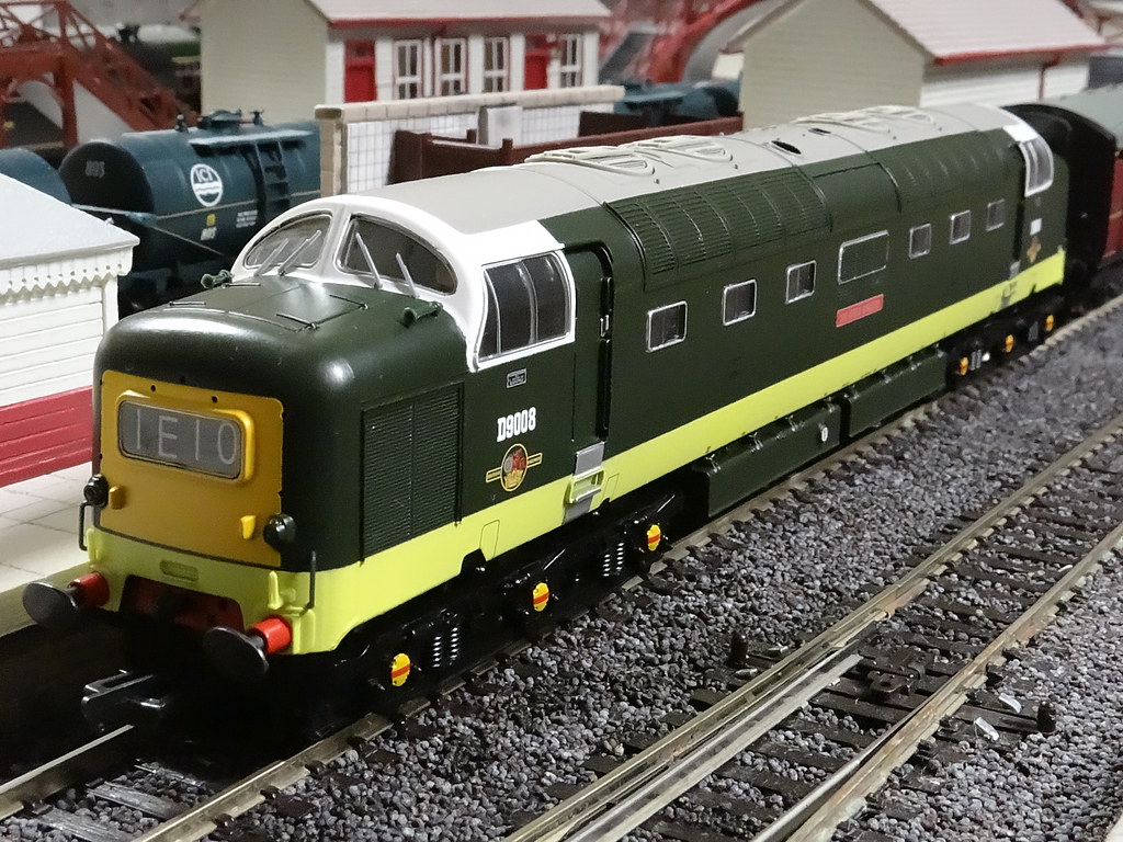
Bachmann D9008 The Green Howards – Limited Edition for the Deltic Preservation Society
After recent successes with running Bachmann sound locomotives on DC Analogue I thought that a sound fitted Deltic would complement my existing Class 40 and Class 45 models. I would add digital sound to my model,‘The Green Howards’.
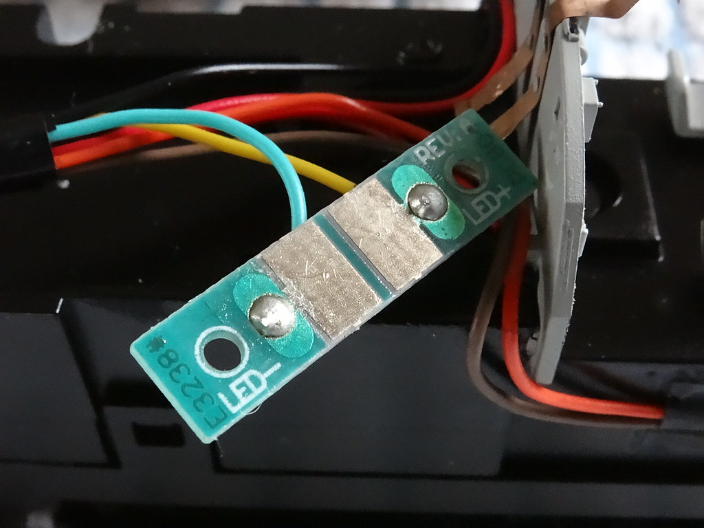
Speaker cavity in Deltic ‘The Duke of Wellington’s Regiment’ – Note factory hard soldered connections for cab lighting
Bachmann have produced a factory fitted digital sound Deltic and the metal chassis has a shallow cavity machined in the top for a speaker. Recent Bachmann Deltics have a 21 pin socket and the factory fitted sound model is fitted with an ESU LokSound V4.0 chip. The perceived wisdom is that this ‘standard’ sound system does not capture the deeper notes so characteristic of the prototype locomotive. How to proceed?
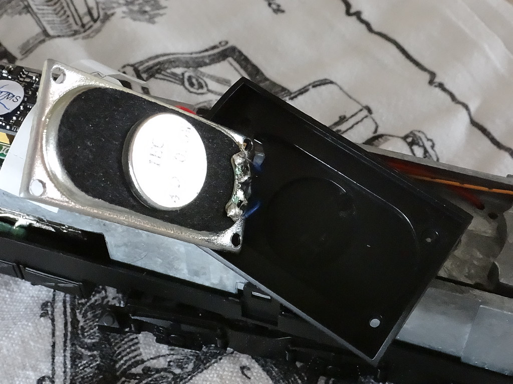
Standard speaker packaged with ESU / LokSound V4.0
There are numerous articles on the internet for improving the sound quality of the Bachmann model. Fundamental to all these suggestions is the need to provide as big a speaker as possible. One of the earliest articles was by Ian Harper of Peasholm Models (Railway Modeller January 2010) and currently available on the Olivia’s Trains web site. Ian recommended a bass reflex speaker fitted within the tanks. I noted that the speaker was fitted pointing up into motor cavity without the need to make any openings in the base of the Deltic fuel tanks. A negative point as far as I was concerned was the need to remove metal from the base of the chassis and to lose the ballast weight from within the tanks. The latter weighs some 75g – a significant lump!
‘The bass reflex speaker in the tanks’ approach has been taken a stage further by Legomanbiffo and here on RMweb there is thread with a detailed guide for increasing the effectiveness of such a speaker. In this approach the base reflex speaker is fitted pointing downwards and a new reflex tube is fabricated to fit alongside the speaker. I noted that the size of the bass reflex speaker was limited by the presence of the reflex tube. I also noted that there were significant modifications needed to the Bachmann fuel tanks requiring tools and levels of skills not readily available on our kitchen table. I would look for another approach.
Technology moves on and new speakers are constantly becoming available. Could I fit a ‘sugar cube’ speaker in the top of the chassis? Probably - I could utilise the cavity provided by Bachmann and I would not need to dismantle the model or lose any ballast from the tanks. One downside would be the need to reroute and lengthen the existing wiring for lights and power from the bogie running across the top of the chassis. My research on ‘sugar cube’ speakers took me to the YouChoos web site where I discovered some 6mm deep 8 ohm ‘bass’ speakers reportedly producing a fuller sound than the sugar cube speakers. There are instructions on how to fit these speakers into a Bachmann Deltic. I noted that the speakers were installed facing downwards with holes drilled through the base of the Bachmann tanks. YouChoos favour Zimmo decoders which are shown matched with 8 ohm speakers. The LokSound V4.0 chip is engineered to work with a 4 ohm speaker. From my school days for resistors in parallel (R1 and R2) the total resistance RT is calculated as follows:
1/R1 +1/R2 =1/RT
Hence for two 8 ohm box speakers:
1/8Ω+1/8Ω=1/4Ω
If I wired the two 8 ohm bass speakers in parallel, the combined resistance is 4 ohms – just right for the V4.0 decoder. I had a plan.
I would buy a LokSound chip from my usual supplier, loaded with their Class 55 project. Thank you Kevin at Coastal DCC. I then purchased a pair of YLR-302506 8 ohm bass box speakers from YouChoos.
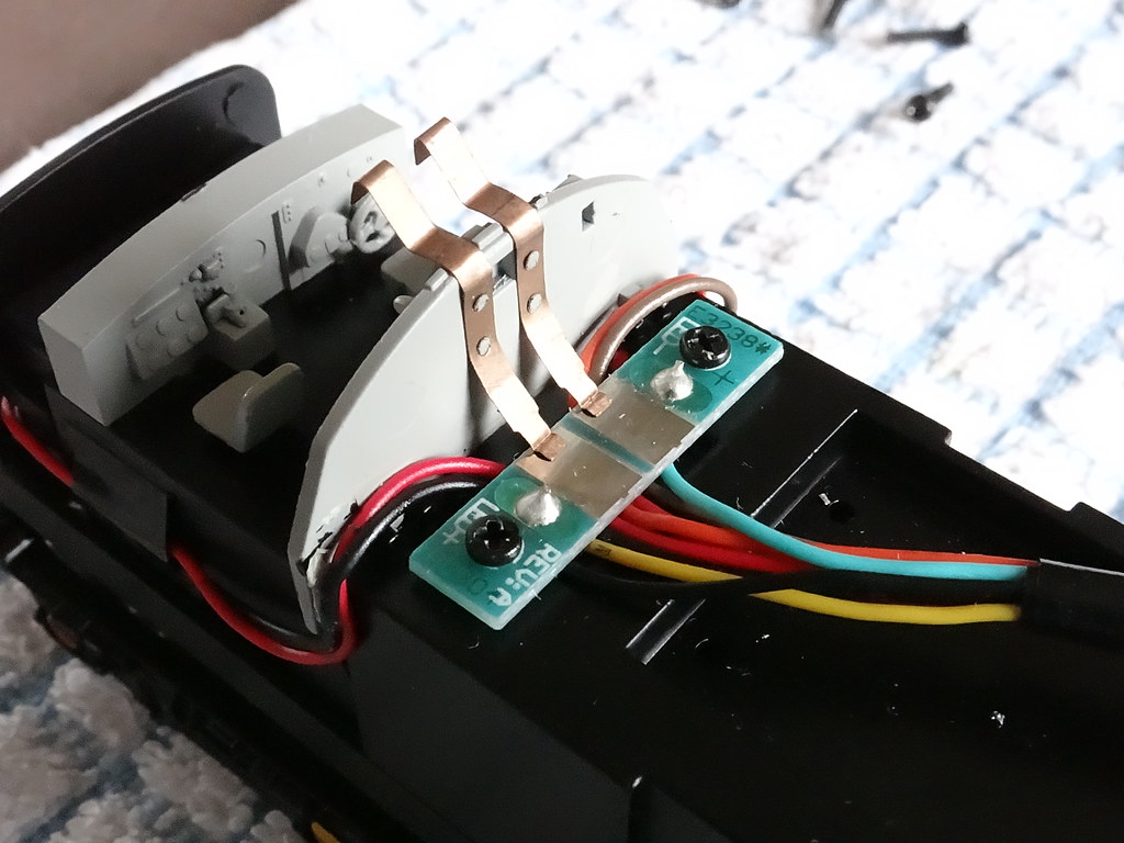
Contacts for cab lighting - Bachmann D9008 The Green Howards
First a word of advice. Before even thinking about disconnecting wires and PCBs it makes a lot of sense to check the fixity of the two pairs of copper contacts on the back of the Deltic cab walls which are for the cab lights. Even if these appear to be in perfect working order I would suggest adding a few spots of Super Glue to keep these contacts in place during the subsequent works.
Having ‘checked’ the fixity of the contacts for both cabs, the chassis can be dismantled. If your model is like ‘The Green Howards’ you are lucky. In this case the contacts rely simply on the spring resistance and do not hinder dismantling. If on the other hand the contacts have been factory soldered then there will be a short delay in proceedings whilst these joints are unsoldered to enable the Little and Large PCBs to be unscrewed and lifted clear of the metal chassis.
Little PCB unscrewed
You are now rapidly approaching 'the point of no return’. Armed with a paper and pencil to note the colour of wires, the power leads marked L and R from the bogies can be unplugged from the Large PCB. With the wires disconnected the top retaining screws for the bogies can be removed and the bogies carefully pulled out from the chassis. At this point I actually screwed the Large PCB back in place as a temporary measure whilst I prised up the four plastic tabs that are used to attach the lower chassis and tank moulding to the metal chassis.
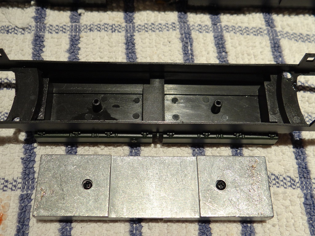
The tank weight
Once the plastic chassis is separated from the metal chassis the internal weight from the fuel tanks can be unscrewed and plastic fixings removed – I used a miniature cutting disc. Using the box speakers as a cutting guide, the ballast weight was marked out and then cut into three pieces with a hacksaw. The centre piece which I retained was notched with the miniature cutting disc to accommodate the speaker wires.
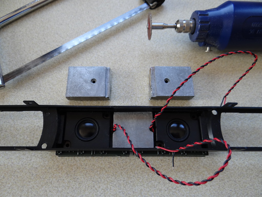
Trial run – fitting the speakers
The underside of my speakers had a metal disc which protruded about 0.5mm from the centre of the plastic box. I used my Dremel type drill to remove some of the plastic in the tank base to allow the speakers to sit flat. I would follow Ian Harper’s advice and have the speakers pointing upwards with the sound filling the cavity for the drive shafts and escaping around the bogies.
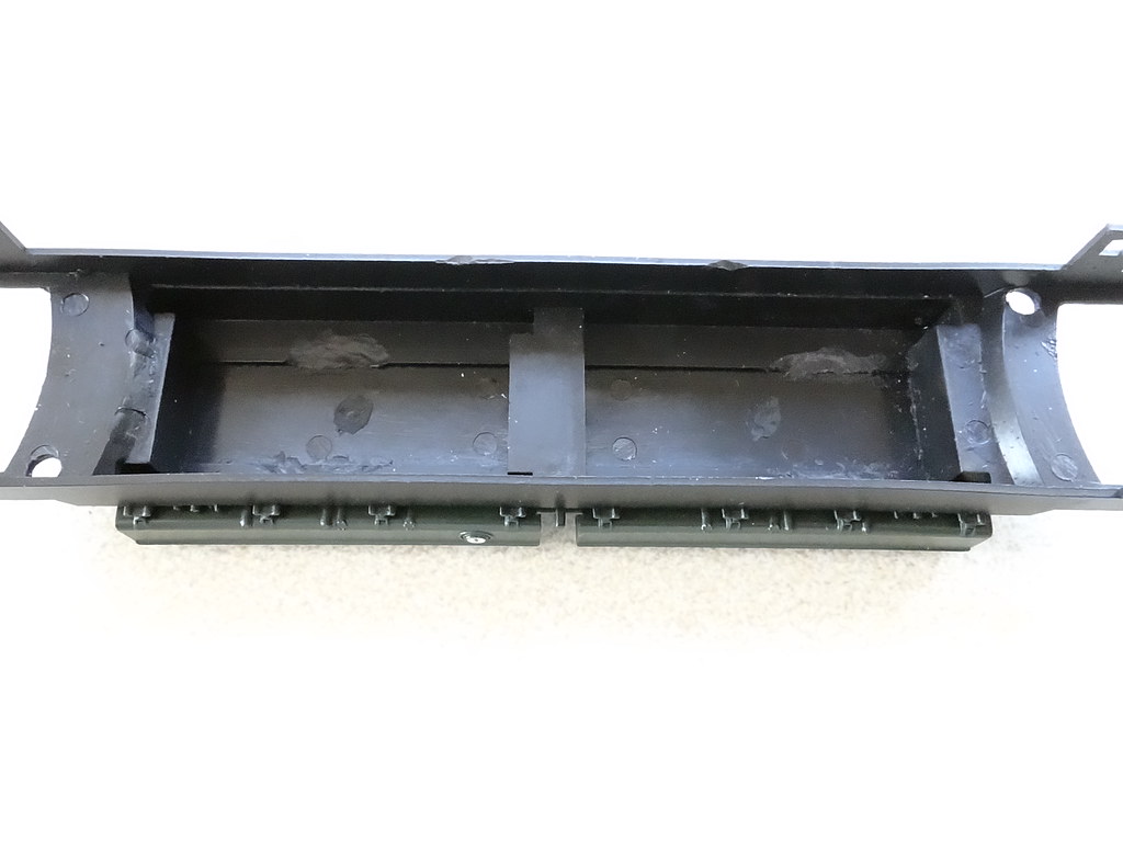
Inside of the tanks prepared
After separating and straightening the red and black speaker wires I used double sided tape to fix the speakers and the remaining centre portion of the ballast weight back into the fuel tanks. With an eye on the finished article you need to group the two black and the two red speaker wires together by colour, black to one side and red to the other. A little bit of black insulating tape will not come amiss.
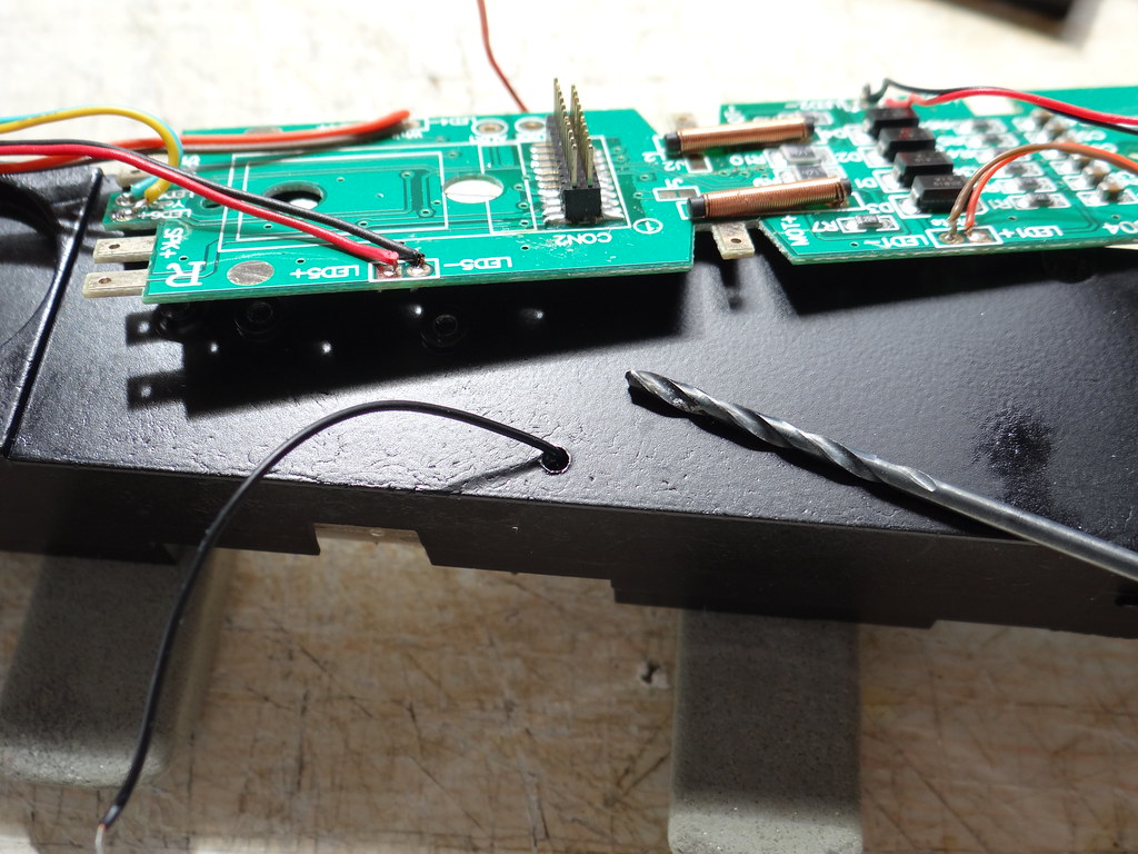
Enlarging the hole for the motor wires to accommodate the speaker wires
At this point I turned my attention to the metal chassis and unscrewed the Large PCB (again). This time I disconnected and unthreaded the two leads to the motor. With the wires unthreaded I ran a drill through the hole in the metal chassis. I didn’t make a note of the sizes but the first pass was made with a bit essentially the same size as the existing hole. This was followed by a second pass using a drill bit one size higher, maybe 3/32 and just large enough to accommodate one motor lead and two straightened speaker wires. You will note that I was able to carry out this work without disturbing the motor which I thought was a big plus.
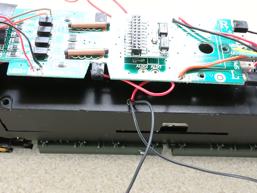
Motor reconnected and two black speaker wires showing
After reconnecting the leads for the motor I then fed the two black speaker wires up besides one motor lead and the two red leads up besides the other motor lead. I don’t think it matters which hole you choose as long as you keep the speaker leads with the same colour together. With the all the leads threaded through to the top of the chassis it is time to offer up the plastic chassis with the speakers to the metal chassis and to clip the parts back together. Care needs to be taken to ensure that the new speaker wires are not trapped by the motor and I used some black insulating tape to pull the wires to the sides of the fuel tanks. Like me you might wish you had more delicate fingers and better eye sight!
With the fuel tanks reattached it is time to refit the bogies, first rethreading the power leads, then engaging the drive shaft before carefully pulling through the surplus power wires and screwing the bogies back in place. It took me a couple of attempts to get the power leads fully through the chassis block without leaving any surplus curled up on top of the bogie.
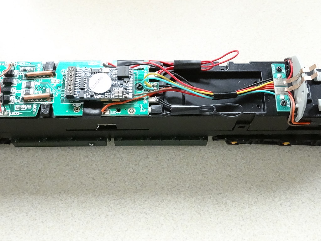
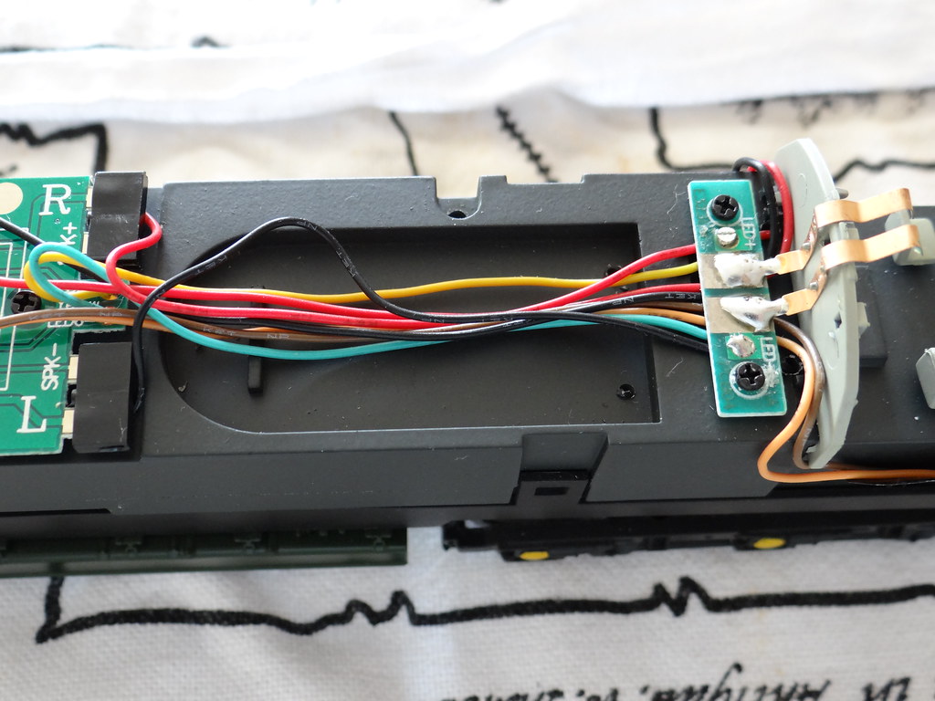
All the wires reattached and the PCBs screwed back in place
It is then ‘simply’ a case of reattaching all the leads and screwing the PCBs back in place. The Green Howards did not come with any black plastic connectors for the sound ‘socket’ on the PCB so the leads from the speakers were attached by solder, keeping the two black leads to one tab and the two red leads to the other tab. Any surplus speaker wire was carefully bundled and held together with black tape.
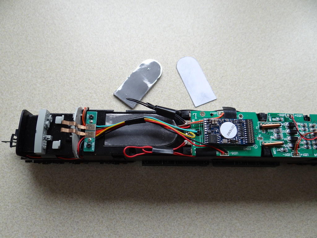
Adding some extra ballast
As purchased, ‘The Green Howards’ weighed just under 600g. After butchering the ballast weight in the fuel tanks the weight dropped to around 530g. Is this significant – I don’t know. However there is the void on top of the chassis provided by Bachmann for their speaker. I made a card template to drop into this space which I used to cut a couple of pieces of lead from 2mm sheet, holding them in place with double sided tape. The net result was to raise the weight of ‘The Green Howards’ up to 570g. There is room to add lots more lead. However my two pieces fitted tidily under the existing wiring and I decided to stop there.
What do I think of the resulting sound? I am well pleased. I did try the engine with the LokSound speaker before making any alterations, it was thin and tinny. The sound from the two bass speakers seems to me to be in a higher league and has certainly impressed a few visitors.
http://youtu.be/HtzlHPExAvc
Bachmann 'The Green Howards' with digital sound running on Analogue DC
As an aside, when ‘The Green Howards’ first arrived on the layout the cab lights did not work at one end of the locomotive. I eventually traced the problem to the connection between the copper strips and the PCB (the ones that came factory soldered on 'The Duke of Wellington's Regiment'). The latter PCB seemed to be coated with varnish or possibly soldering flux. After a light clean with some emery paper the cab lighting was restored. Now after installing the LokSound chip the cab lights were again extinguished (on analogue DC). This time it was not an electrical problem but a case of changing one of the chip's analogue default settings with the SPROG.
-
 6
6

0 Comments
Recommended Comments
There are no comments to display.
Create an account or sign in to comment
You need to be a member in order to leave a comment
Create an account
Sign up for a new account in our community. It's easy!
Register a new accountSign in
Already have an account? Sign in here.
Sign In Now