
router Folding Workbench - Part 3: Machining
Entry posted by SouthernRegionSteam
248 views
As mentioned in the very first part, using plywood for the desk means that we will be using alternative methods to form solid joints. As alluded to earlier, this means the use of rebates; a series of trenches, grooves, and tongues to join everything together. This will of course require another machine to make our lives easier; a router.
As with the Skilsaw, it's another case of doing a little bit of prep work beforehand to make sure everything is set up correctly; but once it is, machining the components is quick and easy work. First, here's an annotated image of the router for future reference:
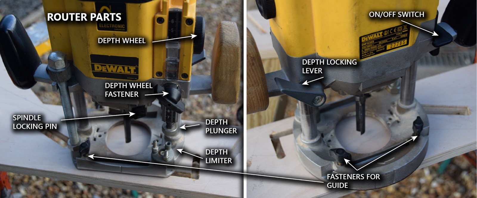
So, now we'll go ahead and set it up properly.
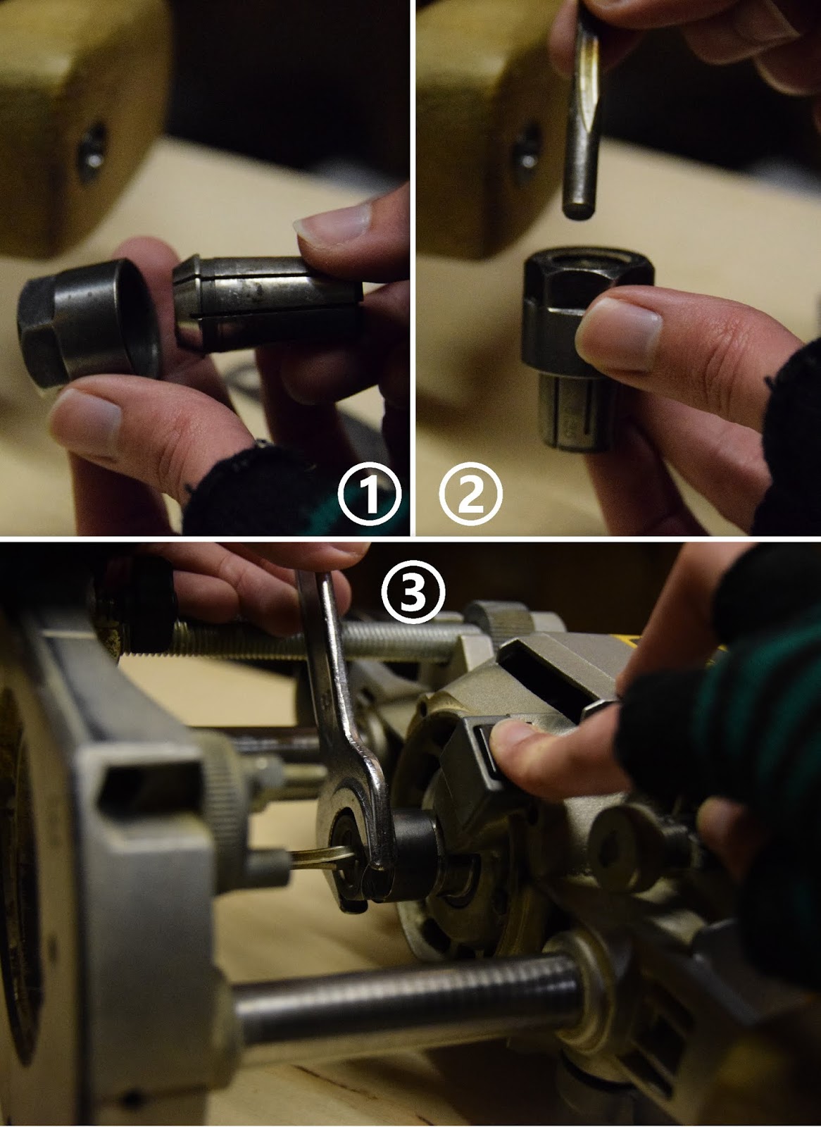
Above: Depending on the size of the shank of the router bit, you might need to exchange collets. (I realised only at the time of writing this that showing step 3 first would make more sense, sorry!) This is done by pulling out the collet (1), and popping the correct sized one in its place. It'll click into position when it is in correctly. Then go ahead and insert the router bit into the collet (2), and then screw the whole assembly onto the router itself. Hold down the button that locks the spindle in place, and use the appropriate sized spanner to fasten (3). Note that when screwing/unscrewing the nut, it will appear to initially tighten, before loosening, then tightening fully. I believe this is due to the way the collet clamps onto the router bit; so make sure you have tightened it fully before using the router.
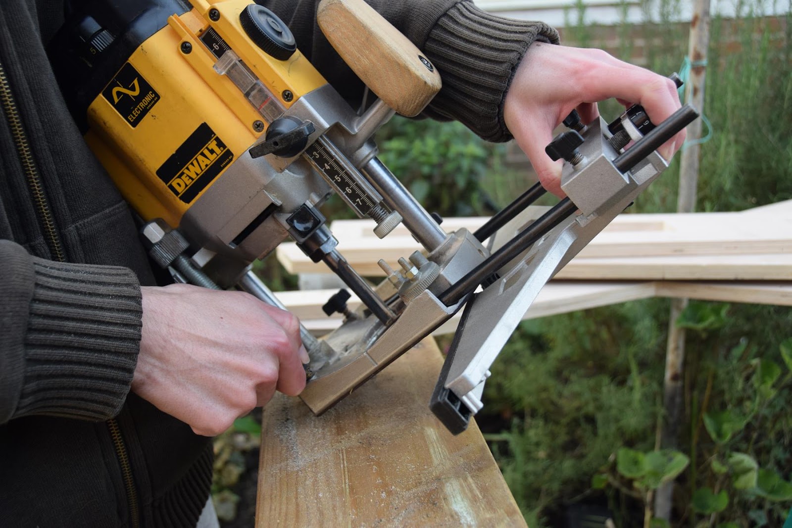
Above: For machining rebates that are reasonably close to the edge of components, it's easier to use the guide that should come with the router. Follow the instructions to put it together, then inset it into the router frame as the photo shows.
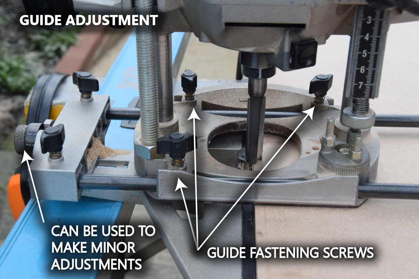
Above: I've annotated a couple of notes to help you identify the parts to the guide. The screws (all 5 of them) hold the guide together, but I only adjust the 3 on the router itself. You can also use the wheel on the left to make minor adjustments, but I don't bother using it, as it's just as easy to undo the three screws and nudge the guide by hand.
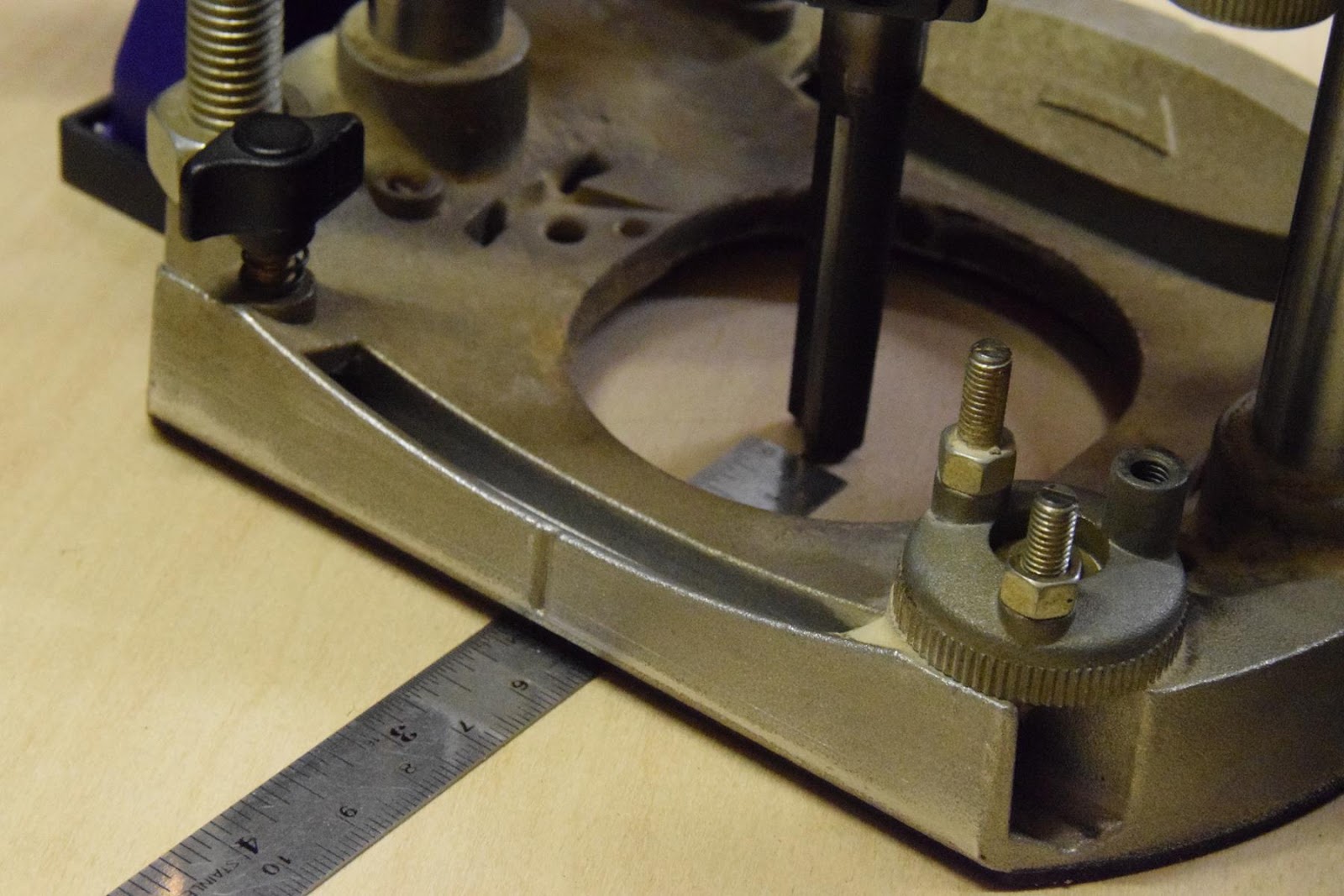
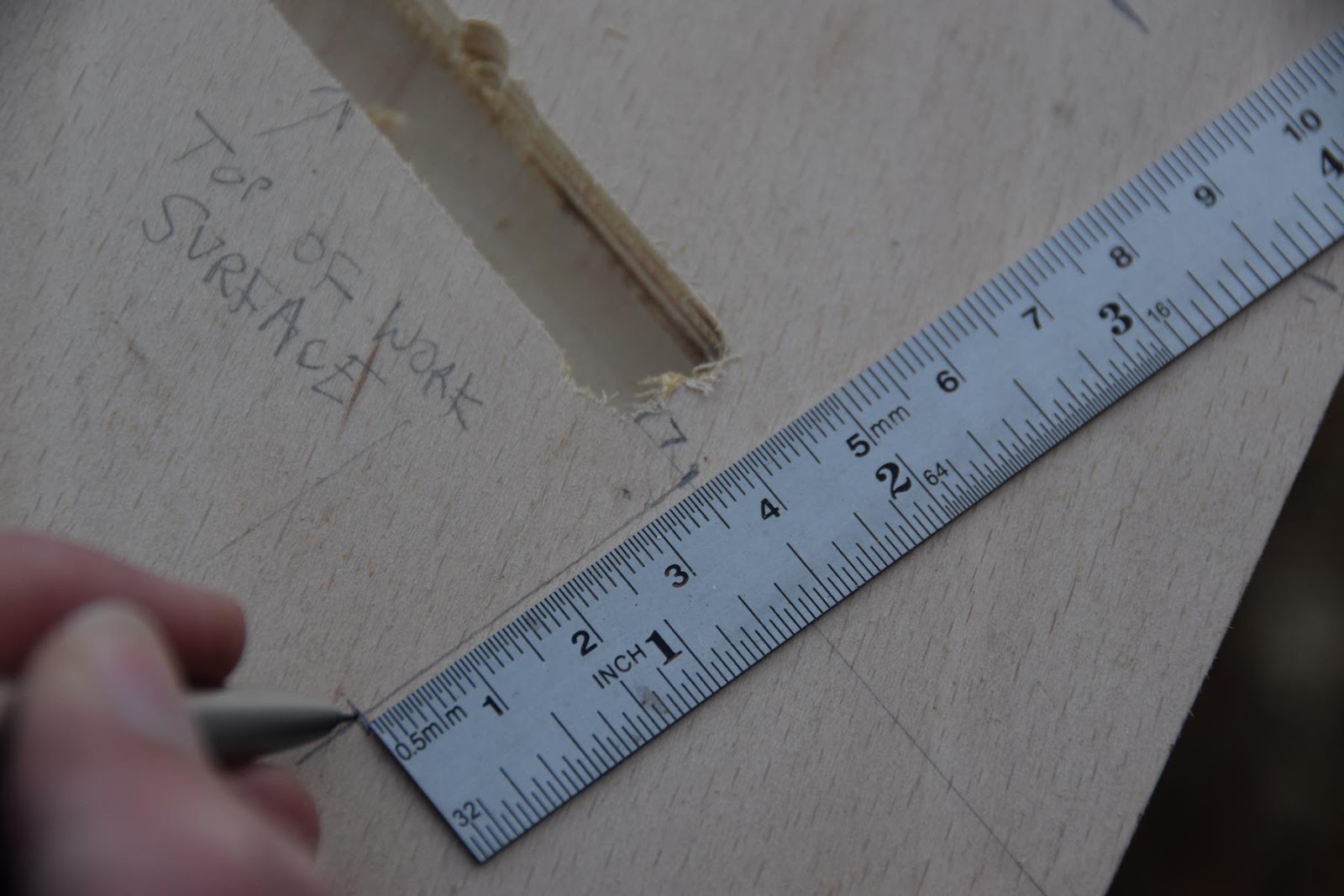
Above: If you're not using the guide (i.e. for rebates far from the edge), you'll need to measure the distance from the closest point of the cutting bit, to the flat edge of the router base, so that you can use it to clamp a straight edge to use as a guide (as we did with the Skilsaw).
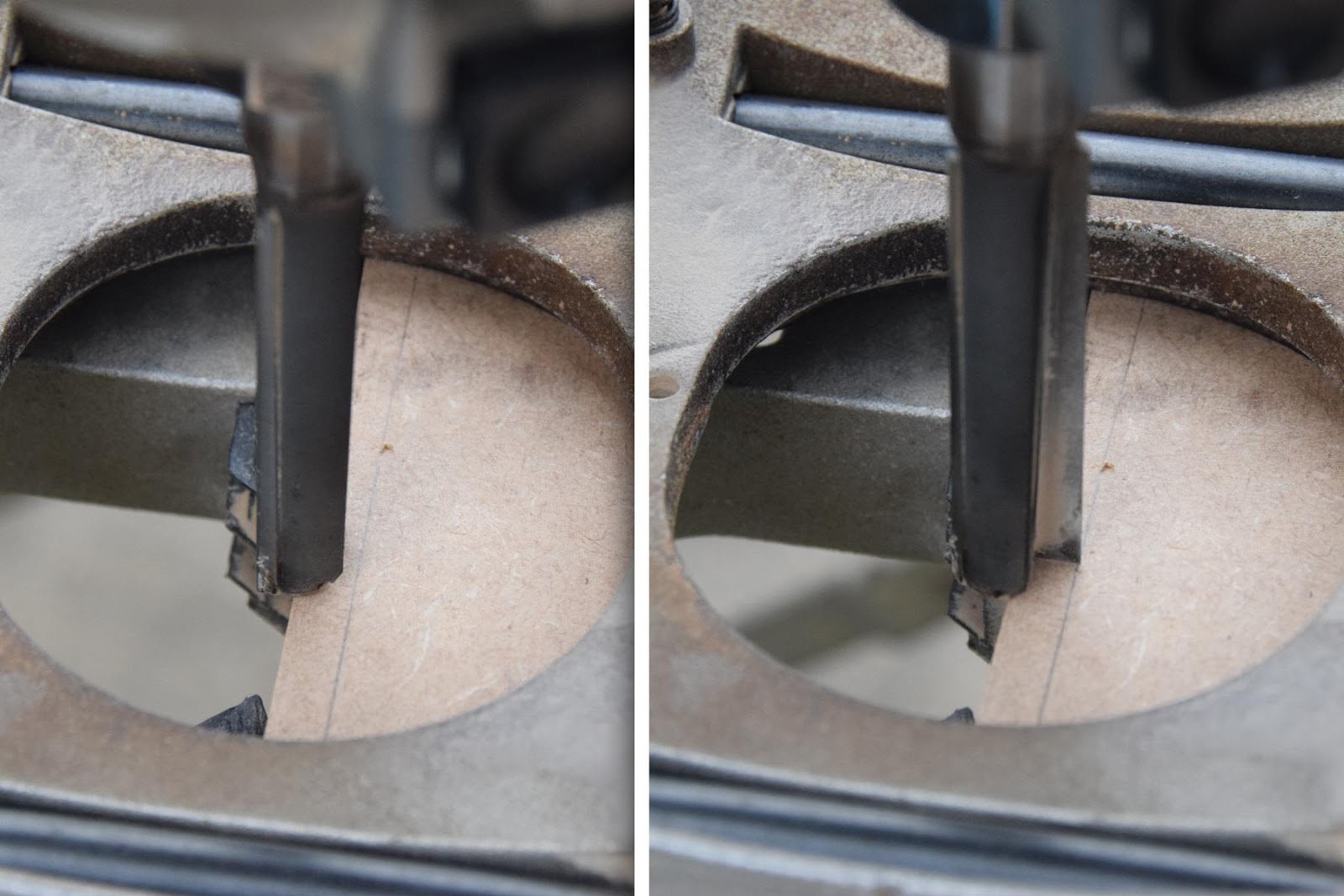
Above: This photo shows how careful you need to be when measuring; router bits like this will have only two points where it is at its widest. Rotate the bit by hand (making sure your hand is nowhere near the on switch (or be safe, and unplug it!)), until the cutting edge is against the waste side of the line.
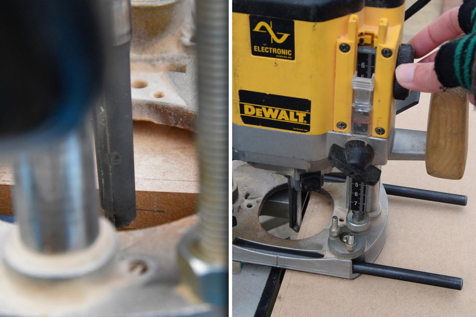
Above: Now we can set the depth of the cutter. On the left you'll see the mark which dictates the depth of the rebate required. Lock the router height at this point (see "depth locking lever" on the first photo), then set the depth limiter. This is done by undoing the knob (in front of the measure on the router, right photo), then rotating the wheel where my hand is, which will drop the metal stopper (under the measure) until it hits the base plate. Fasten the black knob, and your max depth will be set. Don't forget to unlock the depth locking lever on the other side to raise the router back up; ready for use!
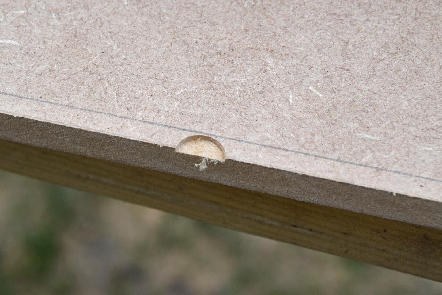
Above: As with the Skilsaw, it's a good idea to do a quick test "plunge". Again, I am half a millimetre out here, so the guide will need to be slightly adjusted.
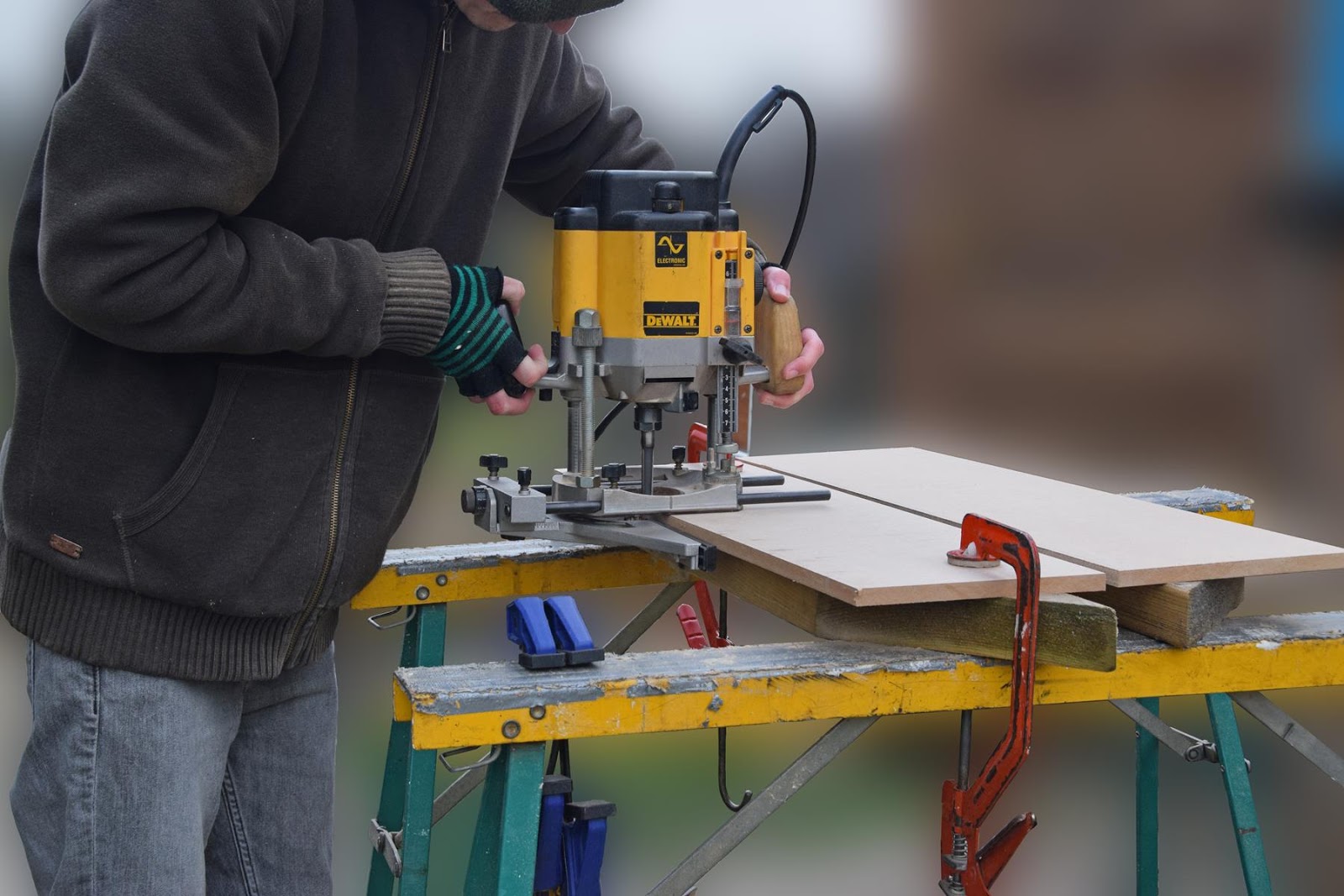
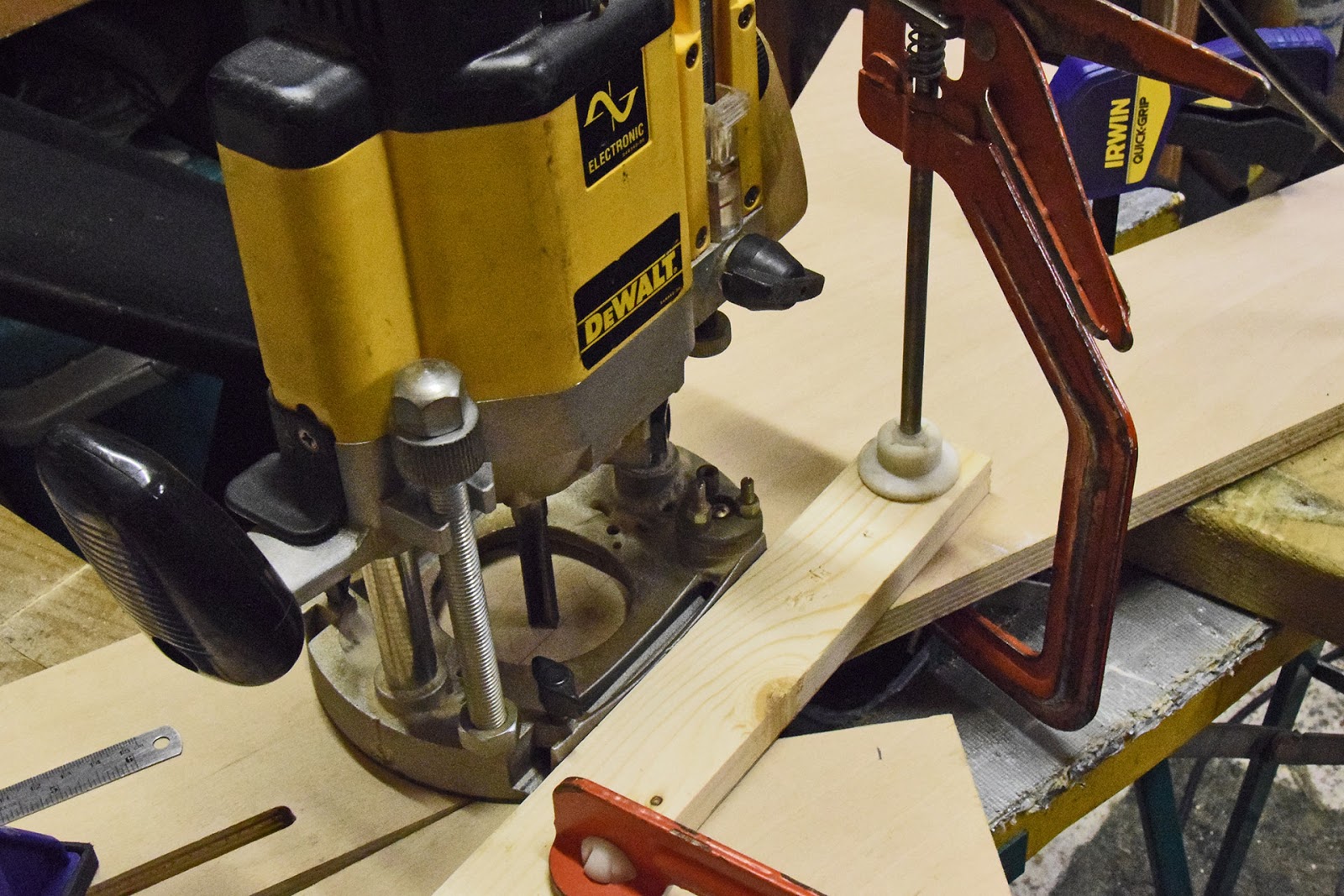
Above: We can now go ahead and clamp the component down (with a spare bit of wood underneath, to keep the router guide from hitting the trestles). Routering is best done in 2mm or so depth increments; especially for materials like plywood, you will not want to try and take the full depth out in one go. You'll potentially damage the bit, plywood, or router if you do! Don't forget that you can use the locking lever to set the depth of the cut at the various heights; I always use it for the final full-depth pass, but I don't often bother in the interim increments. This only slows me down (and the lever can be difficult to release without accidentally moving the router mid-cut). Usually it's not too difficult to maintain an even enough pressure to keep the cutter at a set depth.
Now that I've explained in depth how to use the router, it's time to start machining the components. I won't show you every single component being routed as it'll take forever, but let's tackle the rebates needed in the two legs; as those are crucial to get right.
Above: You can see I've already cut out the rebate that the shelving unit will sit in, but the focus here is that I'm marking out the beginning of the slot that will let the work surface pivot and drop down. If you get this wrong, your work surface will not sit level when in use! I'm actually drawing a centre line; which is located 7mm in front of the storage section rebate, and 35mm down. The dimensions were worked out from the 3D model in Part 1, but there's no reason why you couldn't work it out on a pad of paper.
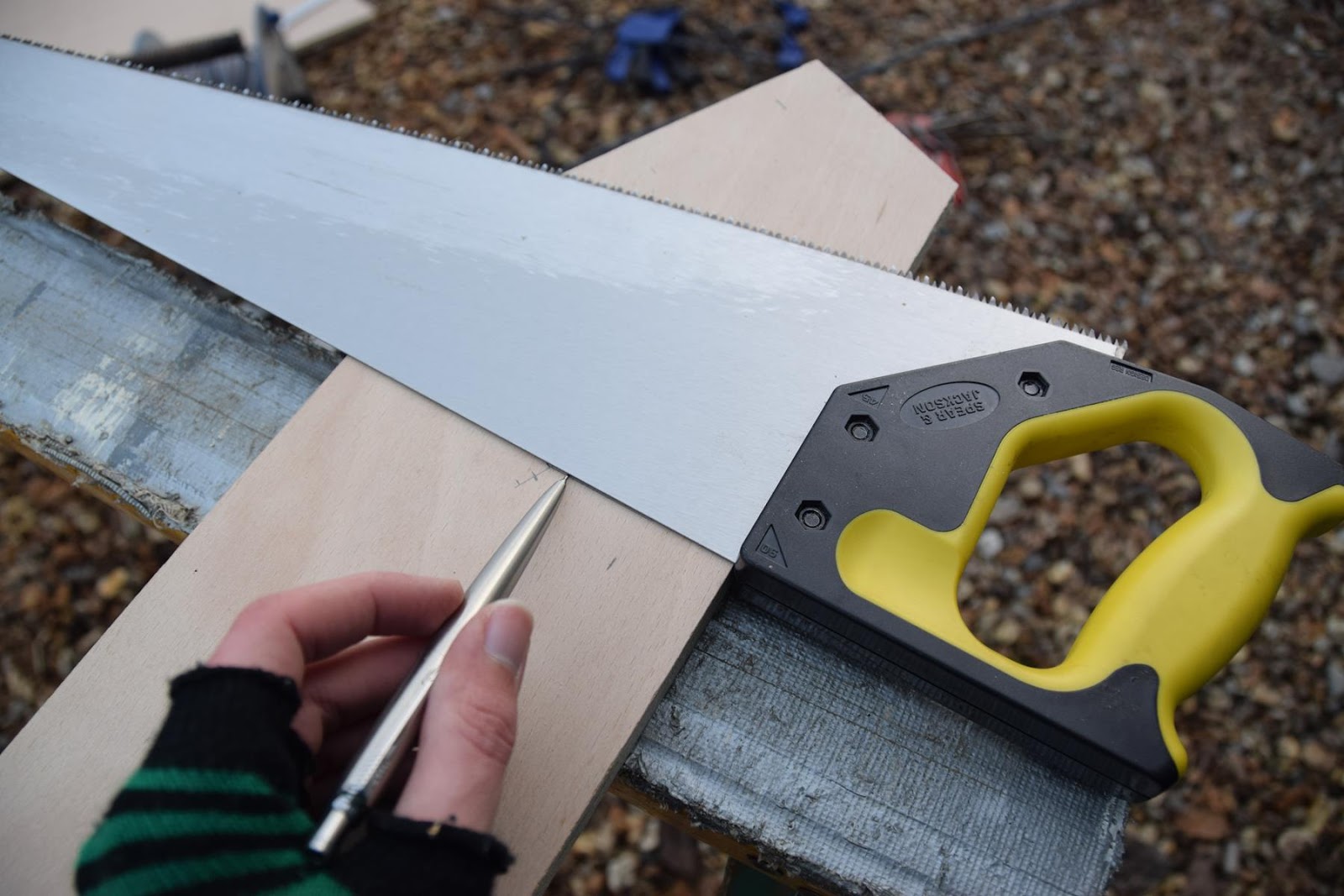
Above: The rebate/hole will be perpendicular to the front (slanted) edge of the leg, rather than being perfectly vertical; this is so that gravity helps the worktop slide into place. Here you can see I'm using a saw (with it's built-in 90 degree angle) to mark it out; don't forget that the line we drew in the last step is the centreline; as we're using M10 bolts, that means the lines will need to be drawn 5mm both sides of that line.
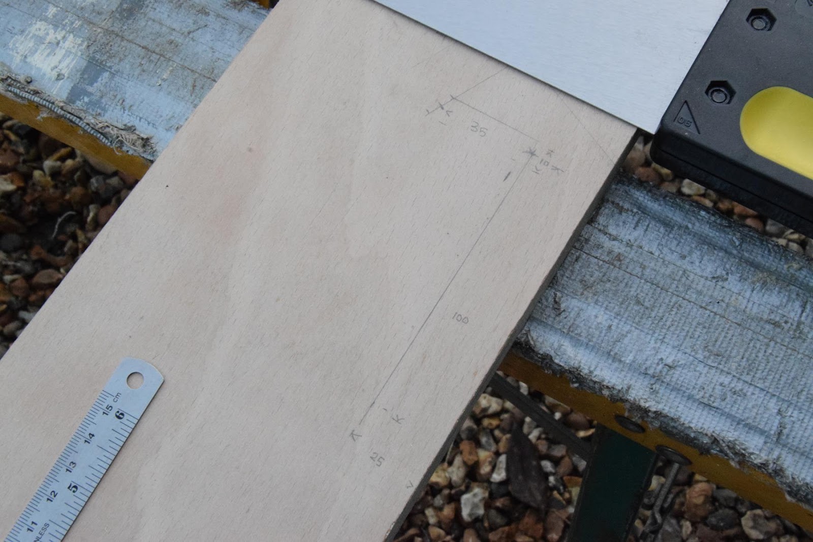
Above: From that centreline, we'll measure another 35mm, this time perpendicular to the very first centreline, towards the front edge of the leg. Well then drop down perpendicular 100mm, to form the drop down guide.
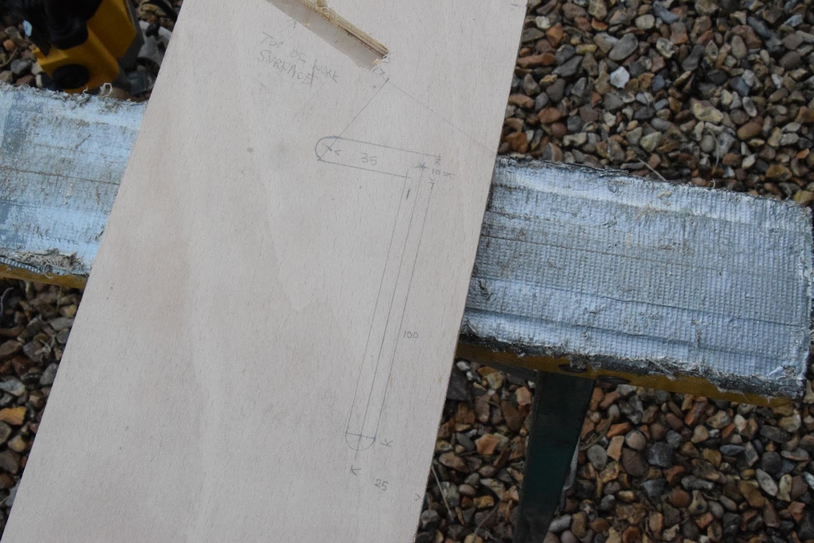
Above: As those are of course centrelines, we'll offset lines 5mm from them. Thus, our rebate is fully marked out.
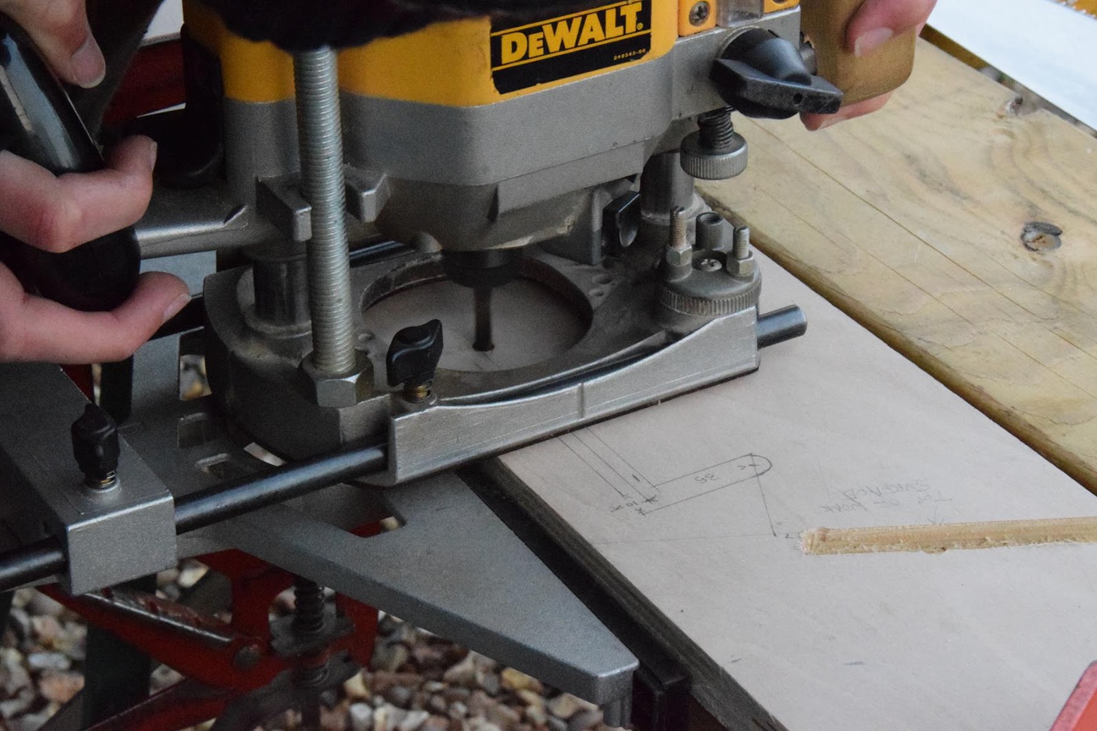
Above: Now it's time to machine it. The shape may look awkward, but if you think of it as two separate straight lines, it becomes infinitely easier. Unfortunately, 10mm straight router bits aren't common (I've never seen one!), so we're going to have to use a 6mm bit and do each side separately.
Above: I've shown how to set up guides, so hopefully you'll have no problem clamping a straight bit of wood at the right distance as shown above. Don't forget to do a test plunge before committing, and also to do several passes; we'll need to go right the way through the 18mm plywood, so take your time and don't rush it.
In order to mark out the holes in the legs for the crossbrace, we will need to form the brackets that will be attached to the underside of the work surface. In my original design, I did not account for the need to add additional framing underneath, so the design here differs from the one shown in the very first blog post.
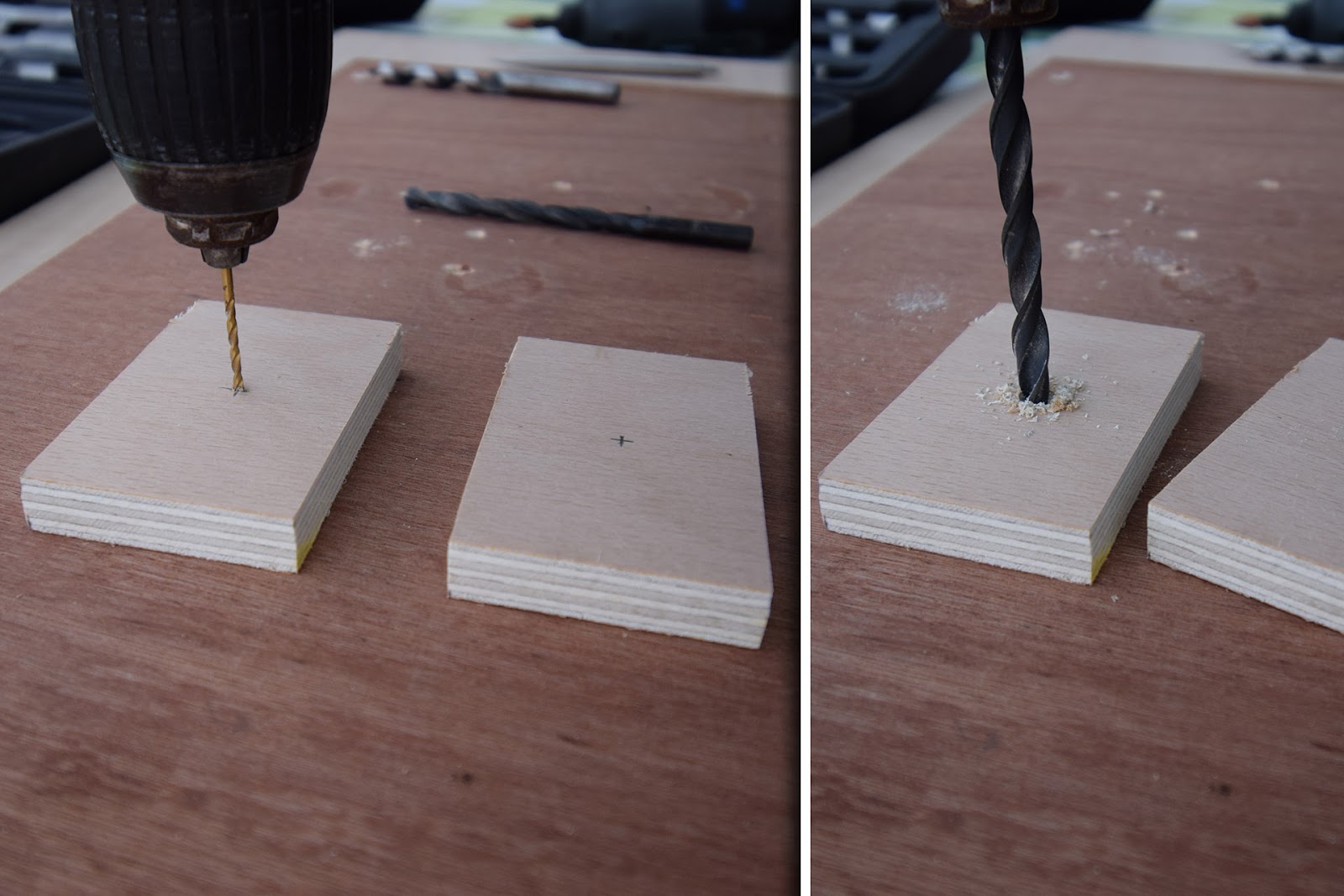
Above: Whilst I drilled the holes for the M10 bolt with a power drill, it is a much better idea to use a pillar drill, if you have one to hand, so that the hole is perfectly vertical. Note how I use a small drill bit to start the hole off; to minimise the risk of the drill bit "wandering".
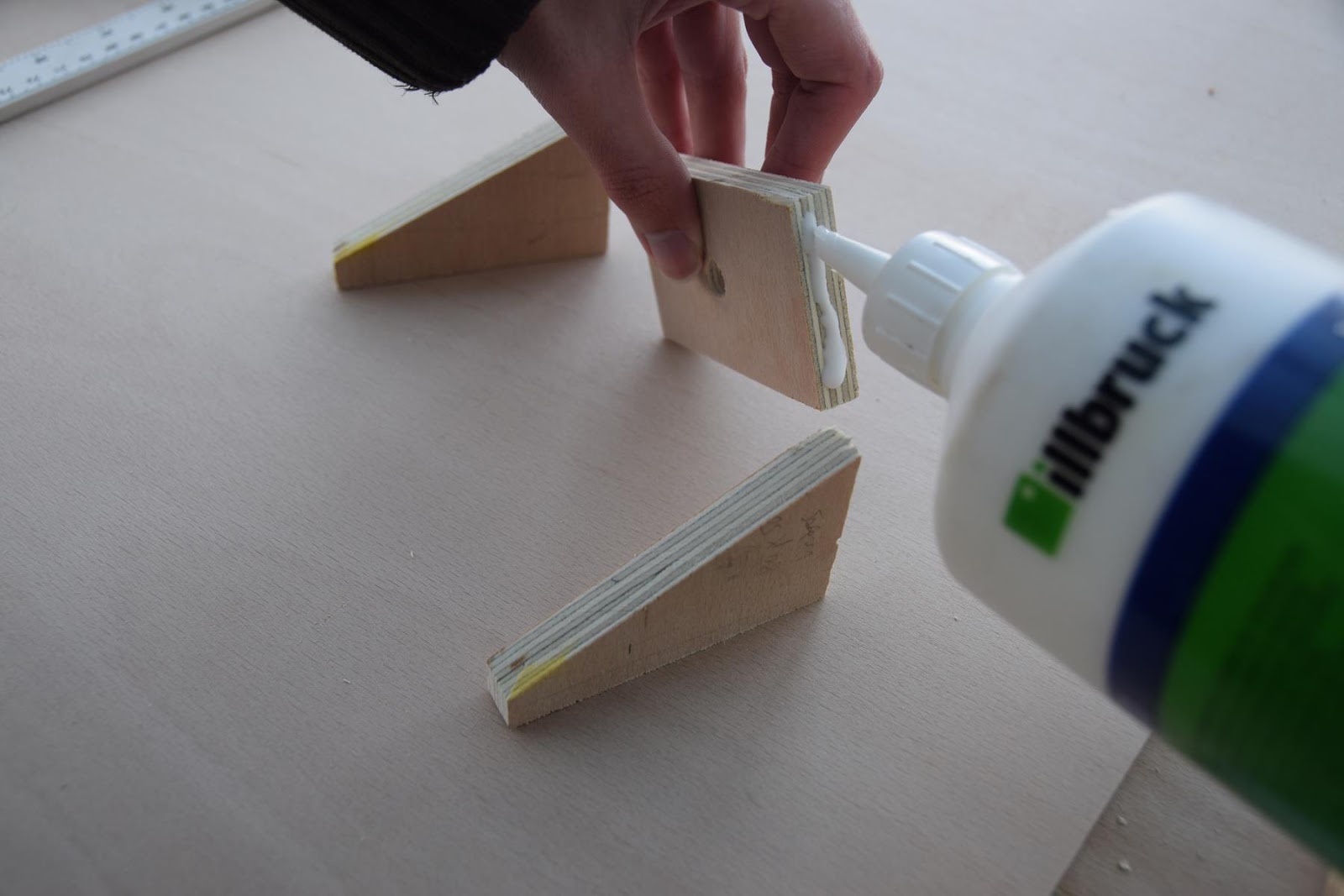
Above: The components that make up the bracket are then glued. Make sure that it stands perfectly vertical! On the original design shown in Part 1, the triangle supports are glued on the inside face, not the outer edges as shown here.
Above: We can then go ahead and mark out the final position of the brackets onto the underside of the work surface, and glue them on. Don't forget to keep the bracket level with the edge of the work surface edge, or else it will not sit flat against the leg, and will likely bind when it comes to dropping the work surface down. Once again, the design differs from the one originally shown, as you'll see soon.
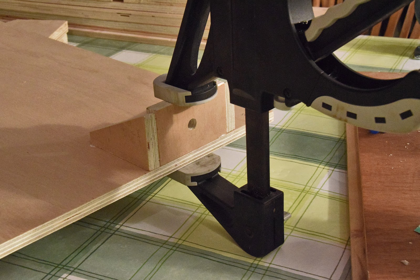
Above: Now that the bracket is rock solid, go ahead and temporarily use an M10 bolt (through the hole that we made for it in the leg), to secure it in place. By positioning it at the bottom (the lower limit of travel) as above, we can rotate it until it is vertical (i.e. not parallel to the front edge of the leg, but perpendicular to the base of the leg, where it touches the floor). Note the first hole made (this side of the bracket) which is the first (incorrect) crossbrace position.
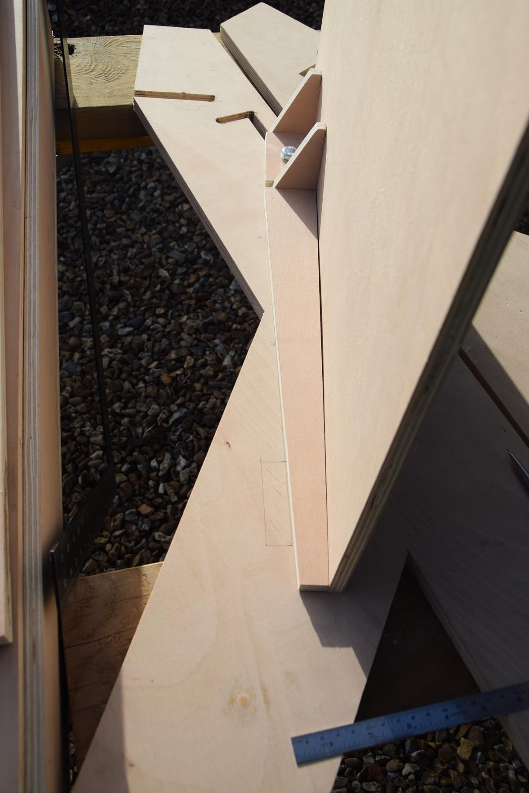
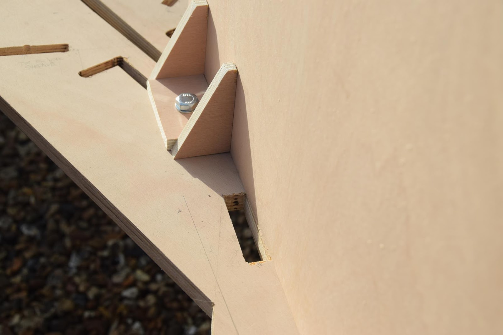
Above: With the rest of the (new/additional) framing added for the underside of the desk, we can see how the original position of the crossbrace would've prevented the work surface from dropping down fully. You can also see the new position of the crossbrace hole,located part way up the rear fork of the leg; which is located so that it limits the swing of the work surface until it is vertical when fully dropped down.
On the version of the desk shown in Part 1, the vertical piece of the bracket (the bit with the hole in) and the additional framing added later are one piece, but the premise is exactly the same.
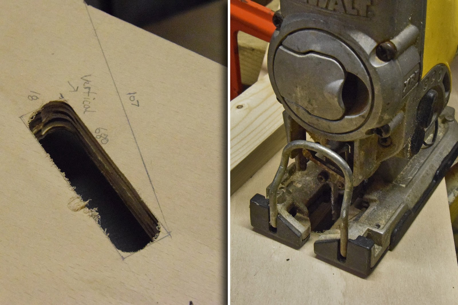
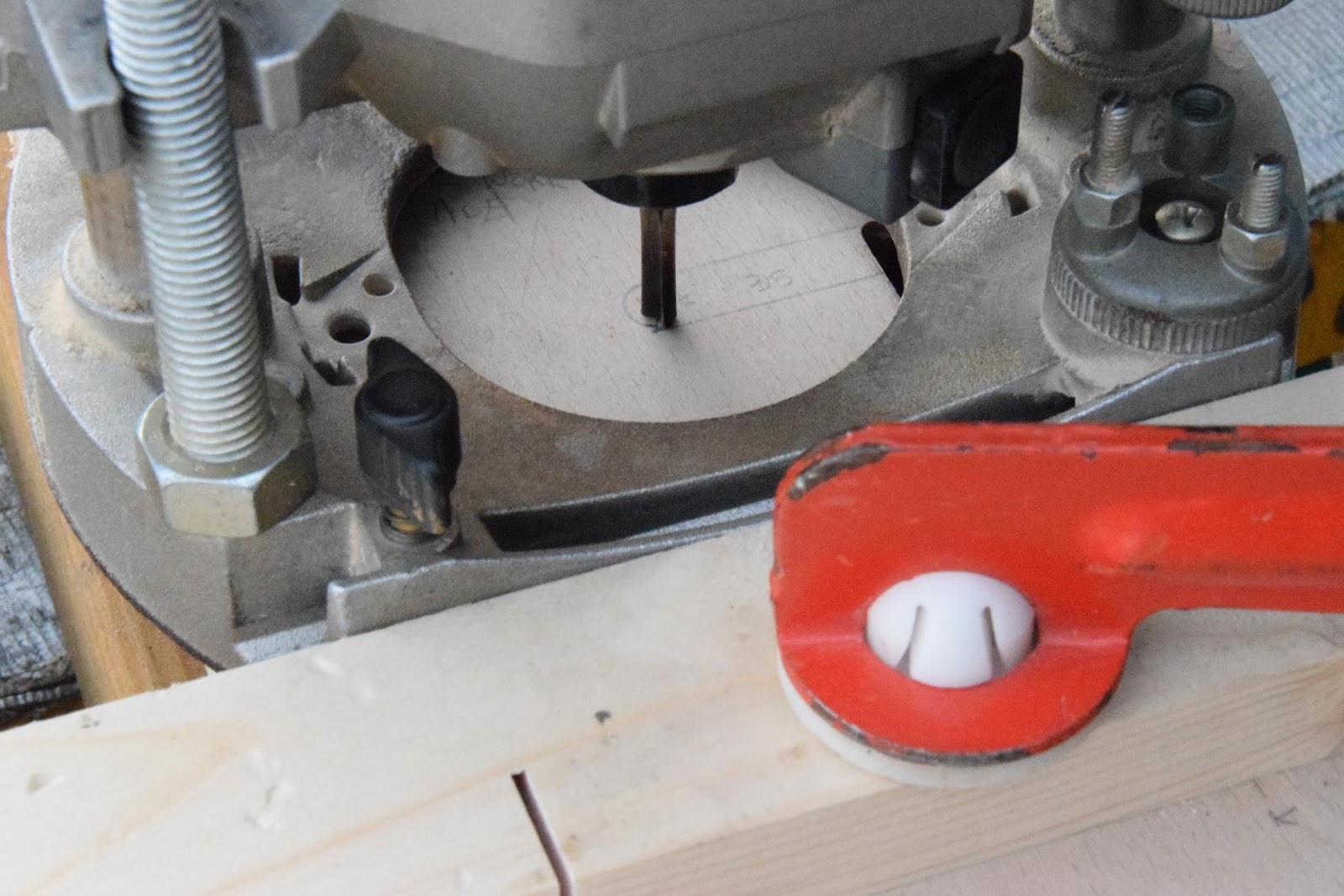
Both photos above: We can now go ahead and cut out the crossbrace hole with the router. As we don't want rounded corners, we'll need to use a hacksaw or battery powered jigsaw to make the ends square. (All three photos show the original hole, but the method is exactly the same.)
Well, that's it for this entry; we've done the most complex rebates in the legs, which means we can focus on the shelving unit in the next one, which should be a little easier!
I hope you're enjoying following along! As always, do ask me any questions you may have.
Jam/Jamie Warne
-
 2
2

0 Comments
Recommended Comments
There are no comments to display.
Create an account or sign in to comment
You need to be a member in order to leave a comment
Create an account
Sign up for a new account in our community. It's easy!
Register a new accountSign in
Already have an account? Sign in here.
Sign In Now