


cg501
-
Posts
61 -
Joined
-
Last visited
Content Type
Profiles
Forums
Blogs
Gallery
Events
Exhibition Layout Details
Store
Posts posted by cg501
-
-
The only Co-Co locos built today capable of doing 100+ are variants of Siemens's Eurorunner EC30 and EC20CF.
They were heavily tested at Czech Railway Research Institute VUZ at Velim, with both types reaching 200kph. Both Co-Co variants produced less track damage than the Bo-Bo variant. which was why Lithuanian Railways and Austrian Railways switch some of their orders, I also think Kowloon-Canton Railway has 5, but these are now limited to 140kph, due to maintenance issues.
a version of Stadler Euro was offered to the US with Co-Co wheel arrangement and 160kph capability.
-
 1
1
-
-
Having been a director of the Electric Railway Museum, I have heard almost every possible solution, to the use of 3rd rail in the heritage and put forward many. The risk documentation required runs in to many volumes and is beyond the pockets of most to produce. You are better off putting that money in to the preservation of the units.
As for running them this has been solved for both AC/DC locos and EMUs.
For AC/DC locos, the former night stock generators cars gave the basis of what mobile power generation was possible. A similar coach could be produced to generate power to enable an electric loco to run on a preserved line. 1500v DC at 1200amps is not beyond todays generators. As people have said no need to run at 100mph with 11 coaches. 25mph with 5 coaches would require less power.
The solution for EMUs has already been engineered and tested by ViVARail. Their class 230 unit using redundant London underground D Stock uses a battery raft, This is sort of solution I will be looking to use on the class 501.
even NR has used the same battery technology in a class 313 .
A youtube clip of the test unit https://vivarail.co.uk/Fully-Charged-Show/
-
 3
3
-
 3
3
-
-
I have loved the 501s for many years, so much so I ended up as custodian of one.

-
15
-
 1
1
-
-
25 minutes ago, 74009 said:
Yes indeed they did look rather elegant in maroon. Trouble is these are refurbished units so it has to be Jaffa livery or later. If I was keeping them I'd go with Jaffa. I do have some unrefurbished sets to build too but these will be blue & grey, which is how I remember them most.
When doing the rub down of the paint on one of 309616s DTs. we found the following remnants of the maroon livery.
-
9
-
1
-
 1
1
-
-
The first 2 pictures are of the DBMS looking towards the guards area, count the number of hanging straps. Pictures 3, 4 are of the DTS only 2 hanging straps denoting small bench seats by the doors only the door mechanisms hidden underneath . From the pictures I have of the set that used to be at ERM Coventry. also the give away for the first 2 is the single bay by the guards door, in the second pair there are 2 bays by the back door. the 5th picture is of the TS as the area beyond the last set of doors has no bays just a bench seat only fitted to the TS, also the seats are the declassified 2+1 first class seats.
-
3
-
-
9 hours ago, roythebus said:
Rail mounted cranes in those days. Have a look at the pictures further up of spans being installed. I doubt that there were many big road cranes in those days.
From what I could find, for sections away from the railway the construction company used 2 cranes, The first was a was a 20 ton lift capable which was block mounted and this was rebuilt when its reach was no longer capable of lifting each beam. They may have used other methods to lift sections close to Bletchley yard, but I didn't find photos of this.
This picture shows where this weekends works to remove sections was carried out but from 1958.
The second was a 15 ton ex rail crane mounted on to a excavator chassis, its boom was extended, but this was used only for the lighter sections
I think NRM have a few more pictures.
-
3
-
1
-
-
4 hours ago, dvdlcs said:
It would be interesting to contrast these pictures with the construction of the bridge spans, should any pictures of that event exist.
The only picture I have found of the beams being lifted into place.
The photo is from the RCTS collection
"Concrete Viaduct Bletchley"
Construction of the concrete viaduct to carry the line from Oxford and Bicester over the West Coast main line South of Bletchley Station, photo by Bob Berry.-
15
-
 1
1
-
-
2 hours ago, Down_Under said:
Do you have the rough dimensions of this plate? Height and thr width across thr RH and Ruston &hornsby part?
The measurements for the RH part are 178mm x 200mm. I took a cast of the plate fitted to DE165 268881 while it was at ERM Coventry and used it to make resin copies to which were fitted to the loco.
The plate over all is 260mm x 345mm
cg501
-
1
-
-
Came across a few great pictures of the fly over being built. When I was researching for my engineering thesis for my Masters. This shows the work involved in building each span.
The photo is from the RCTS collection
"Concrete Viaduct Bletchley"
Construction of the concrete viaduct to carry the line from Oxford and Bicester over the West Coast main line South of Bletchley Station, photo by Bob Berry.-
14
-
1
-
-
2 hours ago, Davexoc said:
Well that depends on what is in the budget for each project, and I guess the A14 budget is the greater of the two.
You'll also find that EWR are going to be removing 14 spans and not just the 3.....
Also I notice that Whaddon Road in Newton Longville and Station Road in Mursley are also both closed. Don't know if that is EWR related, but they both have bridges crossing the line...
It's not so much about budget, its about the bridge, it's design and the available space around, around the Bletchley site there is room for a large crane. At Huntingdon there is no space. Also the beams involved are very different. Each span at Bletchley is made up of 18 beams each weighting 10-15 tons with a poured reinforce concrete deck. The bridge at Huntingdon has fewer spans and less beams, but those beam are more than ten times the size and weight.
But what is more important is that on the A14 bridge they have fitted a safety deck, this means they can work without closing the road or east coast main line, so reducing the disruption to local road and rail users, this in line with department of transport thinking, "to reduce local impact caused my major projects". more thought need by EWR/NR, all work to make the spans safe to lift could be done with no road closures, only closing the roads during the actual lifts.
-
It's funny they can remove the old A14 road bridge over both one of the busiest roads in Huntingdon as well as the east coast main line with very limited requirements for road closures or rail service interruptions. yet they need to closed a road for 6 months to remove or repair 3 small spans.

-
3
-
1
-
-
Is the Bay platform (5) at Basingstoke electrified, I used to remember that the DEMUs from Reading coming in to the bay and those lines which were not electrified. It used to be a straight though platform but was cut back so that the station had better access from the northside.
Andrew
-
46 minutes ago, fiftyfour fiftyfour said:
Four rail to Watford dates back to when the Bakerloo went through to Watford, every bit of stock operated by LUL needs a 4th rail for traction current return purposes, no stock ever operated by BR (except the tube stock on the drain and the Island Line) sends return current through a running rail. Any redundant 4th rail still in place north of Harrow is only there because nobody bothered to lift it, it's broken/misaligned and not connected to anything.
Just to correct you on this information the when BR replaced the trains on the Watford to Euston line, the class 501s were delivered to use 4th rail, with both positive and negative supply shoes fitted.
During the restoration survey work on 501DT (75186) it was found that she still had the cross beams and supports for the center contact shoe.
Andrew
-
1
-
-
Hello Jack not sure it's the right one but try Ebay item 174269302210
-
Hello Marc
A lot of the fruit traffic from Wisbech / Ramsey and other yards in the area, as well as along the Midland and Great Northern Joint Railway went up to Rowntree's in York.
Andrew
-
4
-
-
That's much better, looking great
Andrew
-
1
-
-
22 minutes ago, Darius43 said:
Andrew,
Excellent photos. Many thanks for the link. One thing they show is that the driver’s doors opened inwards. I will need to remove the hinges and relocate the door handles on the model. Shouldn’t be too difficult.
Cheers
Darius
Darius
Just to note there should be hinges on the 3 doors which are housing the grills. top hinge (bottom of the hinge inline with top of the windows). Middle hinge ( just above the bottom of the windows) and bottom hinges are inline with the bottom door hinges on the other doors. I have a picture somewhere of a Motor coach outside Stonebridge Park.
For more info on the units check out the book below, has a few shots of underframe detail as well
Andrew
-
1
-
-
Ron Fisher has some great shots of these units after withdrawal stored at Verney Junction showing the Green with Yellow fronts on this FlickR pages, used these as reference when building my own GEC Sets
January, 1964. Copyright Ron Fisher. - https://www.flickr.com/search/?user_id=40052043%40N03&text=Verney Junction&view_all=1
Andrew Humphries
Class 501 Trust
-
4
-
3
-
-
Did anyone go the the open day on Sunday?
Cheers
Shane
Shane just to let you know, over 700 did go to the open day last Sunday which was the museums largest attendance for a single day.
The Museum also has a petition against the closure of the museum and information can be found here https://you.38degrees.org.uk/petitions/support-a-future-for-the-electric-railway-museum
Andrew Humphries
501 Project and ERM site Manager
-
1
-
-
Hi All,
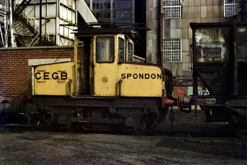
A little request for some help from overseas. I've been trying to get back into the hobby for a little while and design up a few etches etc of the odder, small little industrial locomotives. Like most projects a little bit of slow burner, not helped by the fact 1) work, 2) landrovers get in the way and 3) that I chose something to model that I can't find too many drawings off, but there is a preserved example.
So far I have started with trying to get the basic dimensions right - most of these can be guestimated from chair spacing and height of wagons - well that is what I have done and have this so far:
 Spondon Line Drawing progess.JPG
The only info I have from http://www.emus.co.uk/spdn.htmis that the wheel diameter is 2ft 9". The rest has been guesitmated from the 21t hopper that appears to be being shunted by the loco on http://www.geoffspages.co.uk/raildiary/emidsodd_htm_files/111.jpg
From this I estimate that the wheel spacing is 6ft and overall height a little shy of the max height of a 21t ~10ft 6". I have estimated that the total length is 12ft from photos. Now information I am lacking is:
Overall height
Door height
Height of bonnets
Width
Length
I would also be interested to see any photos off the running gear in detail - brake arrangement etc if anyone has any?
Any help, feedback and comments much appreciated.
Cheers,
James
EDIT - very basic spelling error.
Hello James
Spondon 1 is part of our collection here at the Electric Railway Museum and i will look at getting the measurements you are looking for. I also have a extensive collection of pictures of both Spondon 1 & 2.
Andrew Humphries
Site Manager
Electric Railway Museum
By the way I also have a 7 1/4 gauage version

-
3
-


The Class 89, By Accurascale With Rails of Sheffield
in Accurascale / Irish Railway Models
Posted
wasn't the class 89 extensively tested at Soho depot back in 2021, I would be sure that many sound recording and videos would have taken back then. Not sure if they have been made available.