

Harlequin
-
Posts
5,548 -
Joined
-
Last visited
Content Type
Profiles
Forums
Blogs
Gallery
Events
Exhibition Layout Details
Store
Posts posted by Harlequin
-
-
On the original question: It looks like you’ve got room to widen some of the corner curves. You’ll have to re-lay the track across the lifting section so that it is still turning when it crosses the gaps. Luckily the flap seems to be wide enough to accommodate the curve. You will need to fix the tracks securely either side of the gaps so that they always line up. Most people do this by soldering the rails to something solidly fixed to the baseboards - either brass screws or copper clad PCB.
-
 1
1
-
-
43 minutes ago, Zomboid said:
I'm guessing you already tried, but does the reduction in length that slips would allow compensate for the fact that they don't curve?
I tried all sorts of combinations! I found the formation with slips was just too straight and the curves at the ends that were needed to get the same net angle made the overall radius much larger.
-
1
-
-
I was looking for ways to combine things and the trailing crossover that was already in the station plan looked like a good opportunity to do that so that the main lines could turn sharper under the high level station building.
I did have the "implausible junction" completely symmetrical at one stage but it throws the main lines in a very different direction, like this:

I think that's the tightest it's possible to get that formation to turn without relying on the turning routes through slips in the main line, which I really didn't want to do! (It's a short crossing, two small radius turnouts and six curved turnouts.)
It might still work. There's enough room above. It would mean more hidden running and less room for scenery behind the low level part of the station. Then Chris would have to decide if he wants to keep the crossover in the station as well as the one in the junction.
-
 1
1
-
-
Do you see this control (circled)?
It's not explicitly called "follow this topic" but rather it controls all things related to following and I think it's the one you want.
-
Hi Chris,
Here's what I've come up with so far. It's not fully worked out and some things might be a bit awkward but I think this is a good point to show it to you.
One of my big ideas came to nothing so it's no less complicated than your clever plan, which it is heavily based on.
The major concept of this plan is to combine the elements of your plan wherever possible so that there are fewer separate parts and more open running.
- The goods yard headshunt continues into the countryside scene. It won't look too "urban" out there because it's just a parallel track with a rusty buffer stop at the end!
- I've broken the rules slightly with a short bit of 2ft main line radius between the station scene and the country scene. It isn't fully covered, just obscured by the road overbridge.
- Helices are purple and they cross in the top right corner. (I know they look close to the walls but that's because of the backscene boards. May need some adjustment.)
- The station scene can be wide because you have access from both inside and outside.
- Goods yard can cope with long trains but the layout could probably be improved!!! Note that pulling forward on the main line before setting back into the yard is all done in the scenic area - great fun!
- There's a passing loop around the branch platform for a bit of extra flexibility.
- The "implausible junction" is hidden under the high level station and associated town scene. This allows the countryside run to be really simple with nothing untoward going on.
Here's the top level and the helices with all the scenery removed:
- I imagine that the scene above the "implausible junction" would lift off somehow for access.
- The "implausible junction" is like yours but swapped over and the take-off lines are allowed to cross to make the formation more compact.
- By putting the junction in the curve there are no reverse curves in any of the routes through - they all just keep turning the same way.
- Note that because there's no visible running between station and junction you can make both main line and branch line trains disappear and appear like magic now!
- You can see that one of the crossovers for the junction is combined with a trailing crossover that was already in your plan, between the platforms. So anticlockwise movements up from the storage level appear on scene briefly running wrong-road. There are various ways to justify this and I hope its an acceptable compromise. (Actually I think that crossover could be hidden with a bit of fiddling.)
- I've used R3 and R4 curves in the hidden junction area and the helices.
-
Point motors for the junction would be surface mounted to avoid possible interference withe the storage level below. This can be done because the junction is hidden...

- Baseboard shapes are just indicative sketches, need to be rationalised.
- The helices (purple) descend from the junction, clockwise and anti-clockwise down to the storage level.
Here's the storage level:
- The same helices (purple) are shown on this plan as well.
- Simple set of 7 long storage loops. (I know the turnout fans could be better!)
- The loops are offset and use the corner curve to help even out the helix lengths a bit.
- Long loop at the front for easier fiddling.
- The helices can be used as headshunts for reforming trains without them appearing on scene.
- Nothing really done yet about turning locos...
- Very simple baseboards at this level!
- The thin baseboard on the North side makes the duck under a bit easier.
-
2
-
35 minutes ago, Flying Pig said:
[Making something beautiful]
... is not always the point, Phil.
Well, yes and no, but I was wrong to snipe at DK's Settrack if that's what he really wants to use. It was only meant to be a gentle hint. Maybe it came out wrong. Sorry.
-
 2
2
-
-
4 minutes ago, DK123GWR said:
Its a nice design and it could certainly be made to look natural more easily than my original plan. However, one aspect that I didn't mention at first (but should have done) was my desire to build as much as possible using spare track and rolling stock. As I have no Streamline points, it doesn't really acheive that.
Making something beautiful and using up spare parts are not always comfortable bed-fellows but you might be lucky.
Maybe some other reader will find it useful.
-
1
-
1
-
-
53 minutes ago, rynd2it said:
I have just discovered that the 860044 is not a chip but a blanking plug. I need to buy some chips
Yes, the buzzing is the characteristic sound of a very unhappy DC motor being given a high-power AC signal (the DCC signal) because there is no DCC decoder between the motor and the track.
It shouldn't have done any permanent damage if you didn't have it turned on for too long.
While you're buying decoders (I agree with the others that Zimo are a good choice) buy some spare ones to replace any Lais chips you have...

-
1
-
-
What about something like this?
- The FY is on the left, viewed from the bottom, platform and station building at the top.
- Uses two Streamline Large Y turnouts and a Streamline Small radius.
- Run round completed in the FY. (I would suggest cassettes.)
- The on-scene run round might just handle two Mk1s...?
- Continuous curve on the platform until it reaches the loco release siding (and you could curve that too if you really wanted!)
- Cattle dock off run round loop.
- Goods siding at front.
-
Smooooth...
-
2
-
7 hours ago, DK123GWR said:
Like this? I'm not sure whether the FY would fit under that arranngement and I am becoming increasingly confident that a pair of Mk1s will fit in the platform while a loco runs round under the current plans.
Hmmm, not really...
What form of fiddle yard are you planning? A fan of sidings? Cassettes? Sector plate? How big?
I think for a layout this compact the fiddle yard needs to be an integral part of the plan.
-
If you omitted the turnout that opens the run round loop and took both sides of the loop off-scene you'd have room for your Mk1s. (Use the FY to complete run round moves.)
That might give you a bit of leeway to have the track(s) enter the scene more centrally, which would help with the realism.
You could also give the platform a gentle curve to maximise the length and give the scene a more dynamic feel.
-
3 minutes ago, whizzo said:
HI every one , now this is a very good idea for a layout to fiddle yard ,and save space, it is just a thought, that if the swing bridge piveted in the middle 600 mm the whole train could be turned round, before going into the into the f/y saving the points - + also the balance of the bridge , may become easier to construct - just ideas // - but this is one of the best i have seen /regards Dave
It's a possibility but there would be a couple of problems to overcome:
- The scene would have to be wide enough for the bridge to sit convincingly in it when the bridge is "closed".
- For full circle or even semi-circular rotation a lot of clear space would be needed around it, which would make the bit behind the pivot more difficult to disguise.
-
I think this was reported and fixed a while ago but for me, on a normal iPad running Safari, all the topic content is shown in a restricted width column, the same width as the content on the home page. It’s as if room is being left on the right hand side for the adverts, status updates, etc., which are not shown on topic pages, of course.
I only see this when I’m logged in...
Ah, and only when the Gold theme is applied...
-
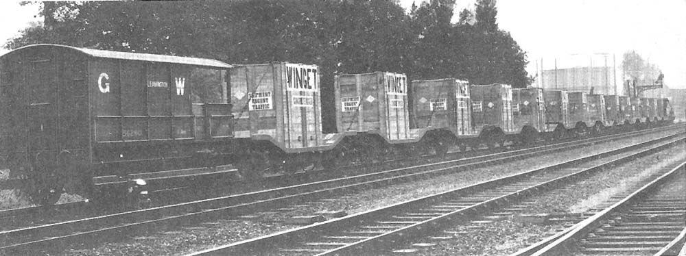
Does this offer any inspiration?
https://www.warwickshirerailways.com/gwr/gwrw2627.htm
You could knock out a whole train of 'em just like the photo!
Edit: Nothing is ever simple... Turns out these are actually Hydras but the basic idea would still work with Loriots in a goods train - or you could start to produce Hydras!
-
8
-
 1
1
-
 1
1
-
-
Thank you!
I have posted a slightly revised version in my Album and the only significant change was that I moved the yard crane because I realised it wasn't in a very sensible place...
David: I can send you a PDF version that you can zoom in and examine in detail if that's of interest.
One thing I forgot to say was that I imagined a typical sequence of events for the history of this station: Independent company first builds the railway, later incorporated into the Cambrian, then the GWR and on into pre-Beeching BR ownership.
-
 1
1
-
-
Here's a suggestion using all Streamline turnouts, then:
- Very similar to many of the plans above. A highly compressed design and so you have to accept some compromises.
- R2 radius end curves with Streamline curved turnouts (20° and 8°!) forming the transitions to straight.
- R2 is tight but it means there's space for the terminus pointwork above and room for the passing loop below.
- 3 coach trains are just about possible if you're willing to have the loco stand foul of the points in the passing loop of the bottom station.
- The terminus headshunt is long enough to move 3 coaches between platforms and carriage siding (the 3rd one down).
- The 3 "goods yard" sidings at the top station could be anything you fancy. In reality they are probably a "scenic fiddle yard".
- The goods sidings are held 67mm away from the nearby R2 curve to prevent collisions.
- Platform widths just about within regs. Imagine they are wider and simply sliced by the edge of the world. There's just room for a very low relief station building at the top if you want it there.
- The inner platform at the bottom station isn't long enough for 3 coaches but it's OK for shorter trains to stop, for trains to pass each other and can be used to terminate local services from the big station.
- The green area is lift-off scenery covering the 2ft square access hole and forming the tunnel over the right hand end of the oval.
- I left some space at the left hand end of the oval for scenery and to give the terminus sidings more space.
-
Special turnouts:
- Small Y in the industrial area to divide the tracks very quickly.
- 3-way in the terminus to maximise siding lengths.
- Large Right giving a smooth exit from the terminus out to the main circuit.
- Dotted tracks are optional.
Have I got the size of the extension board correct? 800 by 500mm?
Actually the design works slightly better if it's rotated by 2 degrees. Then the space is used better, the platforms are wider in places, there's more room for a station building and everything feels more dynamic. But it would be tricky to lay out!
-
6
-
1
-
According to "GWR Signalling Practice":
The first tubular post signals were erected at a number of sites in 1927 for assessment and comparison with the old pattern masts. Thereafter they gradually extended across the system.
(There! That makes up for my late arrival on the Diagram T autocoach train!)
-
1
-
1
-
-
42 minutes ago, Dungrange said:
https://www.enigon.com/raily/modules/en/ho_peco_streaml._code_100.html#_ states that they are 6.85 degrees for the outer track and 18.81 degrees for the inner track, so closer to 7 and 19.
Hmmm, OK. They seem like very odd angles so I guess they are measured from actual parts which may have some tolerance and variability.
I can't remember now where I got my info from so I'll have to do a bit more research.
-
15 minutes ago, OhOh said:
Just did a little exercise combining an SLE-87 curved point with r3 Setrack in order to see what length and radius of SL-100 would be needed to complete a 180 degree turn.
While the tracks diverge at 12 degrees, the radius (if my calculations are correct) of each is 7 degrees outer and 19 degrees inner. That might already be obvious to some here, but I often like to take the long route to finding things out, hence the illustration below.
Gra.
8 degrees outer and 20 degrees inner.
-
I'm sure it's possible to do the whole design in Streamline without needing to do anything too drastic - IF the main circuit is single track.
The turnouts don't have to be in the tight end curves - in fact they can help the transitions between curves and straight like this:
(The red circle is a guideline for an R2 curve. The green turnout is Streamline HO/OO curved left.)
I'm drawing something up. Might have something to show later today.
-
2
-
1
-
-
The proportions of your plan look a bit wrong to me. The very long very shallow angle on the right squeezes the shed to the left. Could you get that track to turn a bit more and open up the angles? Maybe have a look at the old mapping web sites.
I think you really need two loco lines beside the shed because you can see in the photos that the coaling shelter was over the outer line with a coal wagon standing beneath it.
If you moved the turnout for the "14 mileage" to the left and/or the TT to the right the TT would fit more naturally in the angles between the lines.
-
1
-
-
On 14/08/2020 at 11:17, chrisf said:
Nick and Alex
If anyone tells you that all GW auto trailers look the same, tell them to ** ***** and ********!
The one nearest the camera looks to be a Diagram T, of which there were 6 [75 - 80]. Nearly all wooden trailers had pairs of droplights somewhere on the bodyside but these don't. I will send a PM with a broadside photo, for I don't want anyone at Domestic Duck Books accusing me of a flagrant breach of copyright. You may think that this is a teeny weeny one but I could not possibly comment.
Vacancy, to be filled immediately: GW coach expert. Tolerance of Twitter would be an advantage.
Chris
Deleted. Never mind. I didn’t get the Domestic Duck jape.
-
Hi Adam,
You're on the same wavelength as me, as far as the sort of traffic you want to see running. (I hope your 47xx is a good-'un - mine's dead and in pieces.)
I've designed a few "roundy-round" layouts that do the kind of thing you're looking for. You might get some ideas here:
I would certainly suggest keeping your trackwork simple and think about what you really need. You can usually add interest back into the plan once you know that the basics will work.
Remember that when a train has been running and then stored you will usually want to run it the other way when it comes back onto the stage, as if it was doing the return journey. To do this you need three things:
- The train needs to crossover and run on the other line.
- The loco needs to turn around (usually).
- The loco (and guard's van) need to be on opposite ends of the train.
Some of that can be done by hand but you really don't want to be handling your locos too much so ideally you need to provide track formations that allow those 3 things. Your current storage design doesn't do that yet.
The 4ft deep baseboard is too deep to reach across when something goes wrong at the back (and it will) so you need to think about how you are going to access the backmost tracks - even for mundane jobs like track cleaning.
The two purlins crossing your attic space are going to be a real challenge for you.
-
1
-
Superb and very witty! Thanks for sharing.
To paraphrase Basil Fawlty, "Don't mention the Minories! I did, but I think I got away with it!"
-
 1
1
-


Eastburn - Aire Valley 1950s
in Layout & Track Design
Posted
It's superb! I would say that you have performed something of a miracle to fit this so neatly into the space but I know that it's really the result of a lot of hard work and fine tuning.
I like the new angle at the bottom, which eases the corner curve and gives the goods yard more room.
Only question is about the turnouts on the access bridge: If the bridge is a lifting flap the proximity to the edge might be a worry unless you have a cunning plan in mind.
Have you thought about the landscape profile? It would be lovely to see some undulations, especially if the landscape could fall away from the track somewhere to avoid the billiard table look.