


LNERGE
-
Posts
3,605 -
Joined
-
Last visited
Content Type
Profiles
Forums
Blogs
Gallery
Events
Exhibition Layout Details
Store
Blog Comments posted by LNERGE
-
-
Do you think the one just downstream of the Little Ouse was ever connected to the standard gauge network?
-
On 01/08/2019 at 12:11, Dave Holt said:
David.
It's all looking very nice indeed.
Regarding the facing lock mechanism, if you want the lock to be visible, Ambis do a very nice etched version. Otherwise, you can hide it all under a ramp type cover. On mechanical rodding FPL's, there was usually a detector bar on the inside of one of the rails to prevent unlocking if any stock was standing too close to the point switch.
Hope you don't mind, but here a some photos of how I represented this on my Holt layout. It was ex-LNWR so the arrangements might not be quite right for your location, but the principles probably apply.
Overall arrangement with FPL to the left and the fouling bar drive to the right. The bar is inside the lower rail.

FPL with drive and representation of point blade and lock detector rods. In this case, the FPL was actually moved by a connection from the detector bar, rather than direct from the signal box. Thus, if the bar was broken or became disconnected, the FPL could not be moved and the signals not pulled off.

Fouling bar moved from the far end so that a broken bar does not give false indication. Spring device took the weight of the bar to reduce the effort needed to operate.

The bar itself, was made from brass angle with the Ambis cranks soldered on using a simple card jig. To plant the bar, pegs were attached to push into holes in the cork underlay. I had to cut off the bottom of the cranks to get the bar to sit at the right height, so as not to catch on wheel flanges. Unlike the prototype, my bar is not attached to the rail.

Hope that gives you some useful ideas.
Dave.
The footpath up to the castle has been shored up with boards held in place by some very suspicious T shaped material. I have a photo somewhere.
-
 1
1
-
-
I look forward to seeing it. 12 inch to the foot taking up all my time at the moment but i haven't forgotten the Arlesey thing.
-
There was very little on the shelf at Long Melford..
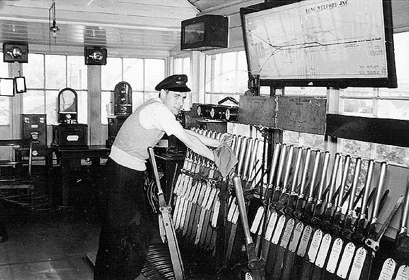
It is possible it didn't have one with any indicators being on bits of wood attached near the windows. There needs to be a telephone too. This was sometimes mounted on a board. I can supply photos/dimensions.
I think there were six linewires on the poles in the more remote locations. I'm guessing at token line and return, omnibus telephone line one and two. This leaves two wires and these could have been control phone or a Cambridge - Colchester trunk. I've not seen conclusive evidence either way. If it is a control phone circuit there would be another phone of different dimensions to the first.
Another thing visible at Long Melford is a trolley token release instrument. The Clare/Haverhill Tyers No6 instrument i have has the contacts to operate with a trolley token release instrument. My research suggests there may not have been one at Clare but again i have nothing conclusive.
-
Clare box was abolished before the line closed. The tablet instrument was removed and taken to Haverhill. The tablet section was then Haverhill to Cavendish. The key token instruments were removed from service. The tablets were rather crudely altered as seen on Dave's website.
I may have the actual tablet instrument from Clare tucked away under my model railway.
I have just provided key token working to a heritage line with two terminal and two intermediate instruments and an omnibus telephone line. All very reminiscent of the Haverhill North to Clare section with it's intermediate instruments at Stoke and Sturmer.
-
The key tokens are the wrong shape! <G>
http://www.trainweb.org/singleline/stour_valley_line/stour_valley_line.htm
A superb bit of modelling.
-

I've found one picture of the inside of the box you can have if you want. I took loads but can't find them at the moment..


Fen End Pumps - Prototypes pictures of old pumping stations
in Fen End Pit's Blog
A blog by Fen End Pit in RMweb Blogs
Posted
A fascinating system of railway. The narrow gauge system south of the Ely - Norwich line equally so. I have a wheel and a few bits of rail and Jubilee sleepers from that system. I get a call now and then from the farmer out that way when he ploughs up a bit and i nip out and get it. It's all junk but quite interesting.