Andy Keane
-
Posts
2,190 -
Joined
-
Last visited
2 Followers
Andy Keane's Achievements
6.2k
Reputation
Bookmarks
-
Software for control
Newbie Question - DCC/Computer ControlThe question you pose is almost as open a question as can possibly be asked and could result in as many recommendations as there are options on the market. There are several considerations that you could make that might limit the choices available and help in recommending a system to buy into.
Considerations are
- Do you want to connect from the computer to the layout via USB or wired LAN or WiFi? There are many that support USB through add-ons, there are fewer that support LAN and fewer that support Wi-Fi.
- What control protocol do you wish to use? LocoNet has the best range of products available, but RS Bus, RBus, Xpressnet, CBus, Canbus, S88 are all options and there are very few systems that support multiple protocols
- Would you like to use walk-about Wi-Fi controllers? There are very few systems that support the use of Wi-Fi controllers. The Wi-Fi controllers can either be dedicated units or software installed on your phone - or even both.
- Do you want to have Railcom for automatic loco identification on your automation program? Often dismissed by people not familiar with the benefits of Railcom on an automated layout I would consider this as a must for any new layout.
- What is your level of expertise in building electronic kits? If you are confident then there are some available kits that will reduce the costs but increase the complexity and range if options available.
- Commercial or Open-source automation? Many will immediately say Open-source in the belief that this is free and reduce the costs. There are 2 major commercial packages available with one less than 50% the cost of the other yet providing all the features of the other. Commercial has the usual advantages in integration and look and feel.
- Your desire to build now and consider automating later, or design for automation properly and build later? this is very important as building then later automating is fraught with difficulties and frustration. The best advice is to design for automation now, simulate in your chosen package to iron out issues, then build and automate at the same time.
- What level of flexibility and future expansion do you want? This is important as some systems will offer what you need to start, but are difficult and/or expensive to upgrade from. Others whilst more expensive at the start will last a lifetime and support any size of system.
I have used both approaches in question 7, and am presently helping automate an existing exhibition quality layout and this has taken almost a year already and it is nowhere near complete. Conversely, I recently assisted in the electronic paper development of a large new layout that was being designed expressly to automate and that was completed in 3 months and it operated correctly when first switched on. I suggest strongly that there is a lesson here.
This list isn't complete but I think it does bring out some major issues that need to be considered before you can decide on what to buy, it is a very important decision and I personally think that there are only 2 options, for both hardware and software that could be as cheap as around £350 for software and command station up to £1000 for another option with my preferred option sitting at around £450.
I have deliberately not specified a specific system at this stage, but consideration of the above will enable the correct and informed decision to be made, once and once only.
-
pressfix methods
Chuffnell Regis3 hours ago, Graham T said:The decals are all from Pressfix, and have just been applied according to the instructions provided:
- Place decal in position (easier said than done with the smaller ones, which have a habit of pinging off in all directions)
- Press down gently. In theory, the decal can be re-positioned if required...
- Then press down firmly. I used a cotton bud for this, but need to come up with something better, as I noticed very small threads of cotton stuck behind some of the decals once I'd finished.
- Wet the decal, just with plain water. Again I used a cotton bud for this.
- Wait 20-30 seconds then remove the tissue paper covering the decal. A cocktail stick works for this. I sometimes found that the decal would still move at this point, which is something to watch for. Another firm press down seemed to fix them.
- Use water to wipe away any excess gum from around the decal. In practice I rarely saw any of this.
- Dry the decal - I used paper towel for that.
I wet the decals at step 2.5, it allows you to see if they are lined up better when the paper goes translucent, then press down with the cotton bud once happy with the positioning (I use buds too, it needs to be something soft-ish). A meths/water mix can also be used for cleaning up and softening them a bit when pushing into the plank gaps with a cocktail stick.
-
Tree making
Chuffnell RegisA product I can highly recommend @Graham T is the textured bark powder from Treemendus. You mix it with pva to a paste and paint it on your wire armatures.
-
Track weathering
Elmore1 hour ago, Andy Keane said:Could you reinstate these pictures. They were really useful and I see they went in the great crash.
thanks
Andy
Sure thing, just got to remember which photos they were
So start to finish
this is the primer, it’s Vallejo grey primer which looks very light. The key is to clean the top of the rail between coats

the next stage is to spray the whole thing in German camo black brown
this has had 2 coats
following this is rust layers, using the paint colours ‘dark fleshtone’ and ‘filthy brown’
Lastly the concrete colour for the concrete pots and rodding parts was touched in using Vallejo ‘stone grey’
-
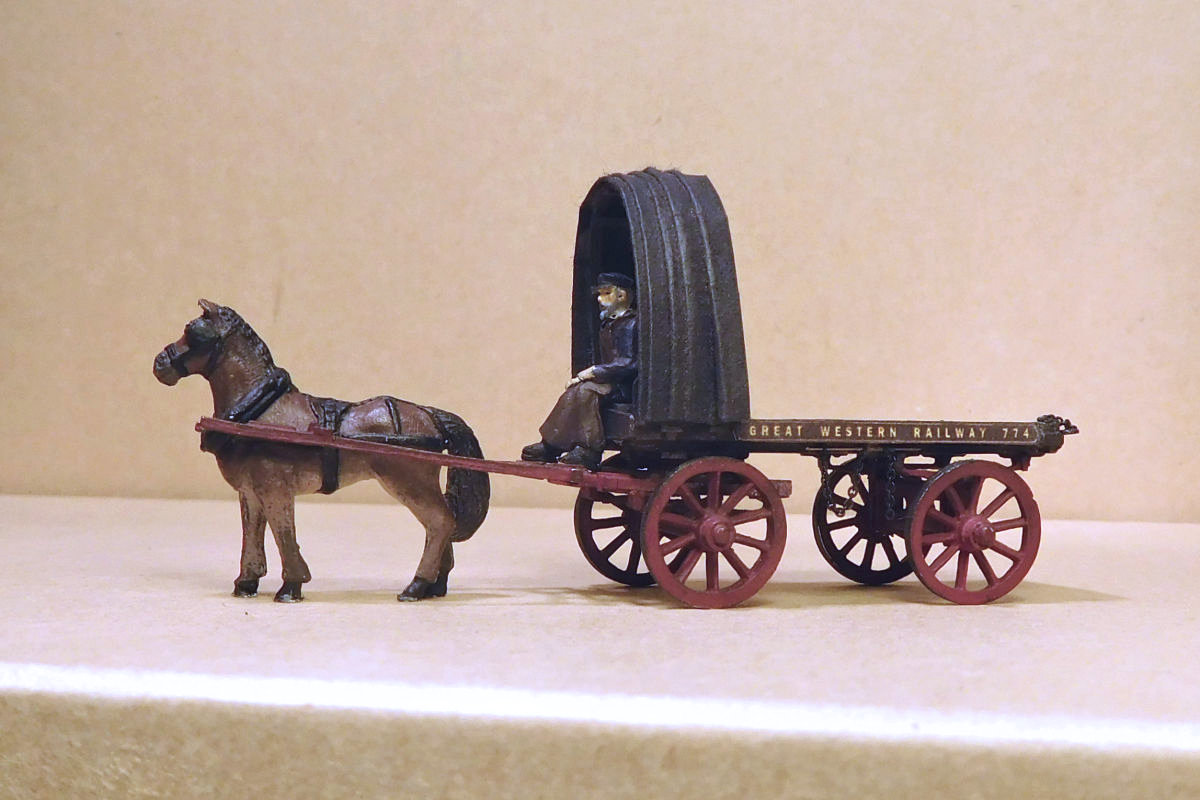
Kit-bashed GWR light dray
Kit-bashed GWR light drayI've been finalising a batch of horse-drawn vehicles for Farthing. First one done is a light one-horse dray – or trolley, as the GWR called them. It's of a type that some GWR drawings refer to as the “Birmingham pattern”. There was a variety of designs of this type from the 1890s onwards, but the main distinguishing feature was the front-mounted protective tarp, and a carter’s box seat beneath it. The name shouldn't be taken too literally. Photos and drawings show that they were widely distributed around the system, including at e.g. Slough and Ilfracombe.
I’ve previously scratchbuilt another Birmingham pattern vehicle, but that took ages so this time I decided to modify a generic Dart Castings kit (ref L45). I found a drawing in 'GWR Horsepower' which is a reasonable fit, give or take a mm here and there. The following photos show the main steps.
I initially fitted bolections to the sides, but later dispensed with them (see below). Probably shouldn't have.
The carter was composed of a Langley body and head from the Andrew Stadden range.
The horse is from Dart Castings. The subtle colouring of our equine friends is hard to capture, I find. Here I tried dry brushing lighter colours on a dark base, i.e. white from below and light brown from above. Works OK in close-up, but once on the layout you can’t really tell the difference!
The tarp on these vehicles could be pulled back and draped over the load in case of rain. I folded it from a spare Smiths tarp, cut to size.
A central box seat was made for the carter. It's a bit lower than it should be, to accommodate his short legs.
Lettering is always a problem for company vehicles. I first used coach lettering off the HMRS sheet as per my earlier model of this type, but wasn’t happy with the result - and the font isn’t right anyway.
After much back and forth I had a "modeller's fit", ripped off the bolections, and fitted a simple printed side. It’s not ideal, next time I’ll make my own transfers. Fortunately, photos show much variety in lettering style in the 1900s. The fine chain is from Cambrian, great stuff and still available from H&A Models.
The new trolley posed next to my earlier model on the left, which shews a different type of headboard (and no box for the driver, must get roundtuit). The scratchbuilt one has more character I think – but the kitbashed one was a lot quicker!
I'll leave it there for now, these entries are becoming too long and unwieldy! More on the other vehicles shortly.
-
Mica B
A Nod To Brent - a friendly thread, filled with frivolity, cream teas and pasties. Longing for the happy days in the South Hams 1947.In fairness I'll post this link to the KR Models Mica B but I'm yet to decide whether to order them. Six different running numbers are listed and also available in packs of three too, with a good saving this way. Like others have said lets wait and see on this one.
-
scenery videos
A Nod To Brent - a friendly thread, filled with frivolity, cream teas and pasties. Longing for the happy days in the South Hams 1947.On 02/05/2023 at 18:03, Ian Hargrave said:Just come up on YouTube: “Back Along The Kingsbridge Line ( 49:48 ) by Aarchive Films
Talking of videos and new member @Dartside Scenics has some excellent scenic videos online. I'm hoping he posts a layout thread as he's building quite a project.
-
cattle docks
ElmoreCarrying on for painting of the cattle dock today.
the brick red is on and the first bits weathering applied to the floor. The bullnose stones have been painted into blue as well. It’s nice to see some bits starting to get towards being finished
-
Townstreet castings
A Nod To Brent - a friendly thread, filled with frivolity, cream teas and pasties. Longing for the happy days in the South Hams 1947.17 minutes ago, Rugd1022 said:Sorry to 'snip' this one from your post above Robin - I rather like the colouring you've achieved on the stone platform walling, it looks suitably 'west country-esque' to me, is it Wills plastic sheeting..?
Thanks @Rugd1022 They are the underrated plaster castings from Pat Lockley at Townstreet. The product comes in a brick or stone 7'' former. SP1 is the stone version and £3 each . They take paint extremely well and the joins can be hidden with their filler. I've also used their similar stone wall castings
https://www.townstreetuk.co.uk/
-
Hornby saddle tank
A Pannier of mixed parentage - GWR 1854 PT (1)I’m building an 1854 Pannier Tank for Farthing in ca. 1919 condition, using a modified Hornby 2721 body, a Bachmann 57xx chassis and various parts from SEF and Brassmasters. Pure it is not. The project has been described on occasion in my workbench thread, but in a fragmented manner. This post summarizes progress to date. Prepare for many close-ups of green plastic 🙂
Background
It's a bit of a nostalgia project. I wanted to do something with the old Hornby 2721, a model I've had a liking for since first seeing it in the magical Hornby 1980 catalogue at the tender age of 11. Note the "X", it was high on my wish list back then. When I finally got one several decades later the running was a disappointment. So it went to sleep in The Big Box of Lost Souls, until I decided to bring it back to life.
The original plan was to make a backdated 2721, but along the way I decided to do the outwardly very similar 1854 PT class instead. The components I'm using match an 1854 PT a bit better, including the plain Bachmann conrods and the absence of visible springs behind the Hornby splashers (a feature of the 2721s). The 1854s were also a bit more widely dispersed during the period in question. Above, I have plotted the 1921 allocations of the 1854s and 2721s into Google Maps. See details below this post.
So the goal is a pragmatic 1854 PT in ca. 1919 condition, a period I have a growing interest in. Ironically I have yet to find a 1919 photo of an 1854 PT. Instead I'm extrapolating from early 1920s photos (including a couple on the gwr.org.uk pannier page), and drawings in the Finney/Brassmasters kit instructions and Russell's "Pictorial Record of Great Western Engines" Vol 1. Thanks to Brassmasters for making their instructions freely available, I try to repay by purchasing fittings from them. The RCTS "Locomotives of the GWR" part 5 is a key reference. Jim's book "An Introduction to Great Western Locomotive Development" has also been useful.
Chassis and body
I’m using a Bachmann 57xx/8750 chassis for the project. Various chassis versions exist, including 32-200 (left) and 31-900 (right). I’m using the former, which is shorter and lower.
Closer look at the chassis. The weight block has been removed to test the fit. Later it went back on.
The Bachmann chassis and Hornby body. There are various well-known issues with the Hornby 2721. Hornby used a Jinty chassis, and so the splashers don’t line up with the more correctly dimensioned Bachmann chassis. The frames and bunker are also too long, and there’s no daylight under the boiler. The chimney is appealing, but wrong shape.
I disassembled the body and was surprised to see that the tank/boiler top is a separate component, well disguised under the handrail.
Butchery
The first job was to get some light under the boiler/panniers. I used a scalpel, scoring repeatedly along the edges of the moulded sides with a used blade, then eventually cutting through with the tip of a sharp new blade.
And there was light.
Then the interior was cut, carved and hacked about until the chassis was a good fit along the sides and ends. The photo is early on in the process, a good deal of material was removed.
The chassis and modified body. There’s ample room for the Bachmann weight block, so that was re-fitted.
The backhead was cut away to allow room for the gears. The motor does protrude a bit into the cab, but will disappear behind a new backhead.
From the side.Footplate
The Hornby body is too long for both an 1854 and a 2721. This is in fact the 2721 drawing from when that was the aim, but the principle is the same for the 1854.
So I shortened the footplate by about 2,5 mm at each end, doing cut-and-shut.
Splashers
The center splashers, being out of line, were then attacked along with the toolbox.
The incorrectly positioned toolboxes, half-relief injectors, and very low sandboxes were also chopped off.
I considered scratch building the replacement splashers as per my Dean Goods rebuild, but wasn’t in the mood. So I dug out a broken old Finecast 1854 that came with an ebay job lot.
The Finecast splashers were cut off, cleaned up and fitted to the Hornby footplate. There are no rear splashers on the Hornby body, so these were also fitted. Will fit bands to the front splasher later.Bunker and Backhead
For the bunker I again turned to the old Finecast 1854…
…and cleaned up the parts as best I could.
The 1854s and 2721s had the same frame and cab width, so in theory the 1854 bunker should be a direct match, but it was too narrow. I thought the Hornby body must be wrong, but checking the measurements again showed that the Finecast bunker isn’t as wide as it should be. Food for thought!
Anyway, I rebuilt the bunker with styrene panels. Later, plated coal rails were fitted. The original Hornby weight block was filed to suit. Along with the weight block on the Bachmann chassis, the loco now runs quite nicely.
The worm and gears were concealed using an old Bachmann backhead, moved slightly back and with a raised section of cab floor beneath it. I’ve done this before, once the crew are fitted I don't notice it.Beneath the tanks
The Hornby balance pipe is a blob one each side of the motor block, so I made some new blobs.
New firebox sides and rear tank supports (adapted to allow room for the injectors) were also made. Drawings of 1854 and 2721 PTs show the balance pipe fitted just behind the front splasher, but photos suggest that they were soon relocated to a position nearer the center of the tanks. So that’s what I have done.
Removal of the “skirts” on the Hornby body exposes the Bachmann motor and lets too much light in. Strips of brass sheet were curved, painted and fitted each side to hide the motor. Testing for shorts showed no problems.
Fittings
The Hornby tank top isn’t that bad, but the chimney (odd shape), tank fillers (too small) and grab rails (moulded lump) had to go. I'm wondering what the small pipes/cables running along the top are for, and when they were fitted.
The chimney was sawn off, and the tank fillers removed (vertical slices in both directions, followed by a parallel cut along the bottom). The bluetack is for protecting details.
Finney/Brassmasters chimney from the 1854/2721 kit, the rest is from Alan Gibson.
Dry fit of the Finney chimney and tank fillers. The safety valve cover is so far an RTR item, can’t seem to find the appropriate shape in brass. I'm confused about the chimney position, forward or center on smokebox? I'm aiming for a pre-superheated version, but despite good photos on gwr.org.uk, I can't work out what it implies in my case.
Tank vents from bits of filed styrene, seen here with the Alan Gibson tank fillers.
Smokebox
The front also needed work. As it comes, the Hornby body has a Churchward pressed steel front. I rather like it.
But pre-1920 tank smokebox fronts tended to be plain, so it was all sanded away. Difficult, and it shows. A ring was added to the smokebox door, not quite the dished look but better than nothing. Alan Gibson door darts fitted, and new steps from scrap bits of brass.
Tank and cab sides
Pannier tanks fitted before ca. 1917 were flush-riveted. After that they were snap head rivetted (1917-1924) and then had welded seams (after 1924). I decided that my loco was fitted with panniers before 1917, and therefore sanded away the Hornby rivets. That took the shine off her!
The lower cabsides are too narrow on the Hornby body, so these have been extended. This photo also shows the plated coal rails on the bunker (which is still loose).
After a hiatus the project is now on the move again. I'm making a new cab roof and have started fitting details. More on that later. Thanks to all who helped with info and advice.For part 2 see:
-
Route categories
Poll: GWR Pannier Tanks; time for a modern spec OO loco.On 24/11/2023 at 08:41, Miss Prism said:I understand that blue-route panniers weren't allowed into Helston, and could only work to Nancegollan?
Sorry to come late to the party on this but a bit of delving through official sources gives the following information -
The Helston Branch was shown as being in the 'Uncoloured' category for RA on the official GWR RA map published in 1931.
As at 1949 the relaxations were as follows -
Yellow 45XX, 55XX, 4-4-0 Earl Class specially authorised
Blue 43Xx, 51XX Not permitted between Nancegollan and Helston.
One GWR/WR document amended up to April 1957 still shows the branch as Uncoloured.
Restrictions published in late 1957 are exactly the same as those published in 1949 except that the 'Earl Class' has been changed to 90XX.
57XX, by then 'Yellow' of course, are not listed as authorised.
As at June 1963 the whole branch was shown as Blue but the only class authorised was D63XX - which were Yellow RA (steam had of course effectively ended in most of Cornwall by then), Either some bridgeworks had taken place OR the 1963 published classification of the route was erroneous - alas I have no amendments to that document which might clarify if it was erroneous or not.
-
sound with coal mesh
Hornby Star sound installation (photos restored)Here's my recipe for installing a big speaker in a Hornby GWR Star class loco to try to get a really strong sound from it.
I used an MX645 decoder because it has 3Watt audio output (at 4Ohms) and onboard stay alive circuitry. In the end I didn't use any stay alive because of space restrictions and with 12 pickup wheels the loco doesn't really need it. I wanted to install an enclosed speaker with a relatively big diaphragm and I settled on what some suppliers call a "MegaBass" and others call a "Box" speaker, which is 30 by 28 by 15mm. I removed the mounting lugs and cut off some material from the top to reduce it to it's smallest, simplest box form.
My technique in all steam sound installations is to give the sound a clear path out, not to be bounced around inside the plastic box before emerging through whatever holes there are in the chassis. To achieve this the speaker will face upwards and it will be hidden by a speaker grille made of coal...
My loco is the 2020 version of Lode Star which is accompanied by a 3500 gallon Churchward tender, not the biggest tender, so fitting the speaker and decoder required a lot of milling and chopping:
(Yes, a brand new loco and I'm immediately taking it apart and carving it up. You've got to have faith to do this!) The weight has been removed and its mounting posts have been milled down to base plate level. The circular speaker mounting has also been milled away, the inside faces of the fixing screw pockets have been removed so that the decoder will fit between them, and some of the base plate has been milled away so that the decoder can sit lower with the wires feeding directly into the central slot.
A lot of the tender's coal space had to be removed because, even with the base plate drastically flattened, the speaker just stands proud of the coal space floor. It will be hidden by the new coal load.The 8pin circuit board has been removed and all the wires routed to the front of the tender through the central slot. The unwanted decoder wires have been shortened but not removed completely so that I can still strip back and solder to them in future if needed.
The speaker is positioned as far back as possible so that the coal load will have room to slope realistically towards the engine (we hope!).
After a few test fittings of the decoder, speaker, chassis and body I knew that it would all fit without any of the components being stressed so the next job was connecting up the wiring.
I had previously noted which of the tender's wires were the pickups and which the motor feeds so wiring up was straightforward: Red pickups soldered to red decoder wire, wrapped in heat shrink and tucked down to the right of the socket that connects tender to loco. Similarly blacks to the left of the socket. Orange decoder to red motor wire, Grey decoder to black motor wire. Purple decoder wires to the speaker. All insulated and then curled gently to fit in the the tender body.
At this stage I tried the tender on the layout, to check that it worked before I went any further. When I played the whistle the tender actually jumped sideways, so I knew I was on the right track to get strong sound!
The speaker adds some reasonable weight to the tender but I glued in some lead to fully replace the mass I had removed and to give the tender enough heft to stop it jumping when loud sounds are played:
Next, the coal load, which forms the speaker grille. A small piece of stainless steel insect mesh was cut and formed to shape:
Chunky real coal was glued to the mesh using Copydex:
The method is to dab Copydex onto the mesh and then pour coal over it, press down and leave to set before shaking off the loose pieces. It takes a few goes to cover the mesh and usually the last step is to fill individual holes with individual bits of coal.
When you hold the finished coal load up to the light you can see that there are many, many gaps for the sound to pass through. However, when it is installed in the tender those gaps are almost invisible. A speaker grille made of coal:
Finally, here is Lode Star back on the tracks with her new sound installation and detail parts added:
During the work I knocked off the tender handrails so they had to be refitted and carefully glued back in place but I managed to do that OK.
She sounds great, within the limitations of the sound project - very loud and the sounds are very clear. (I'm striving for clarity more than volume!) There is a bit of distortion on some very loud noises and I think that's the mesh or the coal vibrating against the tender body. Some tweaking and some more Copydex to stabilise the coal around the edges should solve that.
I will post some videos if I can capture something that does the loco and the sounds justice.