


ikcdab
-
Posts
1,861 -
Joined
-
Last visited
3 Followers


About ikcdab

Recent Profile Visitors


.thumb.jpeg.591a8ee4883006f4327f033a679ecaad.jpeg)


ikcdab's Achievements
2.8k
Reputation
Bookmarks
-
Baseboards
Wentworth JunctionOne board at a time brought into the workshop for wiring at the weekend.

These boards are a bit big and Judith's kit stuff occupies some of the big bench.

Some work on the top first, the new Peco rail joiners are amazingly good - not only are they suitably short and actually look like fishplates but they grip the rail very well. I won't rely on them for electrical conductivity though, all joints have been wired round now (this wire will be buried in the ballast). The V marked on the board shows where a gap has been cut in one rail for a section break, I usually try to arrange these in pcb sleepering but sometimes this is unavoidable. However it is necessary to prevent the rails from sliding in the chairs and closing the gap, here I'm trying out a small fillet of epoxy (Super Steel) in the gap.

The board stood up on its side to do the wiring, some labelling done as well.

The deep baseboard edge on one side makes this quite stable, usually I have to use a G cramp to secure boards like this.

While the board was out it seemed a good idea to do most of the work for the ashpit, lining the sides of the cutout with brick plastikard. Sleeper ends will be trimmed a bit later.

View of the ashpit from underneath.

The next board with the wiring more or less complete, two plugs at the top connect to the control panel which is attached to this board. Back out in the shed next job will be to plug it in and see if it all works...
-
Plastic viaduct
Manchester Central, CLC & GN Warehouses & Castlefield ViaductsCompleted the second link section of ties and windbracing yesterday, then started on linking the south end gable/transom, and disaster
Eleven of the seventeen transverse tie beams which should link to the gable/transom shattered as the solvent was brushed on the joint to the gable span - the gable span remains unaffected. This does happen very occasionally with new styrene strip, but never before on older styrene. This means that another eleven tie beams need to be made to replace the damaged ones - don't want to risk doing a repair job
Took time out, before tackling the replacement transverse tie beams, to produce a mock-up of the roof cladding and glazing. The glazed sections occupy just over 55% of the roof cover. The strip lighting in the railway room is fortunately directly over the centre of the roof. Visibility under the roof cladding, etc. is very good, enabling all the roof structure detail to be viewed easily from below (platform level), and with clear (not frosted/weathered) glazing also allowing good views of the platforms, etc. from above - much better than the prototype ever was
Now have the design of the cladding and glazing to detail, and work up a construction method - timber planking with bitumen felt cover (never worried about the fire risk)
Have also been testing one of my laptops with 6 webcams attached, just to prove that good views of the platforms/track/concourse, etc. will be possible from within
-
Wiring link section
Wiring a handover or link sectionIf you are happy with common rail return then this should work
Both controllers must be fed from different power supplies
In practice if you cant control the link section then throw the switch at your end
Like 2 way switching ( Staircase lights) the position of the switch has no relationship to the light being on (In Oz Switch down = light on)

John
-
Sticking tracks down
Leeds City, the Midland Side, in 4mm.Could you explain the procedure and about the underlay please?
trustytrev.
The underlay I am using is the same as I used on Bradfield, 2mm thick polyfoam that is used for insulating laminate flooring. Once the board has been cut to the final shape and size, it is attached to the adjacent board and the joint finished by applying a 20mm wide strip of plasticard on each board along the joint to form a solid and straight edge. Two pieces of 1mm (40th) plasticard are used to match the height of the polyfoam, the first strip is stuck to the ply board with Evo stick and when dry the second layer is bonded to the first with solvent. This is left overnight to dry thoroughly and can then be sanded to remove any slight difference in height between boards. The polyfoam is then cut slightly oversize and stuck down with carpet adhesive, bought from DIY stores in 2.5kg tubs for about 7-8 quid. The adhesive is spread all over the ply top and then the foam positioned and pushed down with the aid of a decorators paint roller to get all the air out. When dry, the edges are trimmed off. The polyfoam is white and can be marked in biro or permanent fine felt tip pens, I use the latter sold as CD marker pens, £1 in the shop of the same name. I draw 150mm squares so that the track plan can be transferred from the Templot drawing which also has a grid of 150mm squares. The same adhesive is used to glue the trackwork down because it is a rubbery type of solution and does not set hard thereby aiding insulation and providing a certain amount of springing to the track.
Hope this answers your query, if not please ask again. Regards John E.
-
Storage units supporting the layout
Leeds City, the Midland Side, in 4mm.The wood butchery continues apace with the storage units that will support the north fiddle yard.

Lighting has obviously been completed and the floor sealed, also outside work now complete except for a bit of guttering.
-
Good idea for mounting servos
Leeds City, the Midland Side, in 4mm.
Corner board of FY now complete and tested, just a bit of capping to cut and fit. This means that the NFY is now all complete apart from a few tweeks so next I shall be well and truly up the junction!!
Note the stop blocks, hopefully these will prevent certain drivers ending up in the dirt!!
-
Home made controller
Home brew handheld controller (DC)Preamble
Since I rewired my layout I have provided for two controllers to be used.
Once the extension is built the fiddle yard will be up to 8ft away from the main operating position. To make operations easier I have introduced "cab control" where a train leaving the fiddle yard is under the control of the "main" operators controller.
A train travelling to the fiddle yard will be under the control of the fiddle yard operators hand held controller.
switching from one controller to the other is done manually by a switch on the main panel.
This of course requires two controllers. As I only have one (a Gaugemaster hand held) I decided to build another.
This brings me on to the main topic of this bog entry.
Circuit diagram
The circuit of my home brew controller is shown below.

It's a very simple design using only a few components but, the control of locos from this controller is stunning.
Because it is a closed loop controller using the back EMF of the motor as feedback the slow start and smooth running beats a lot of ready to use designs.
Note that there is NO smoothing capacitor, this is because the voltage needs to fall though the 0v point for the back EMF voltage to be measured. If a smoothing capacitor was fitted the controller would still work but, slow starts and smooth slow running would be impossible.
I take no credit for this circuit as it is quite a common type of control for small DC motors.
Constucrion
The controller (less transformer of course) is built into a small plastic box.
The method of construction though needs some explanation.
Instead of using a printed circuit or strip board I have used my "Ugly bug" technique using "islands" of PCB material with the components surface mounted on them.
the picture below shows what I mean.

I did however use a small piece of strip board for the rectifier diodes (seen on right hand side of box).
I find this method of construction very simple to do when just a few components are involved and this method lends itself to prototype development, allowing quick component changes when developing new ideas.
Here's a close up of the main assembly

And finally a picture of the finished and tested controller along side my Gaugemaster unit.

If anyone is interested in building one and needs more info ,I'll be happy to help.
Cheers for now
Frank
-
Setting signal servos
Semaphore Signals - 4mm Scale (Mainly)Continuing with the Servo motor...
How is the operating wire to be connected to the servo motor?

A piece of 1/16 brass tube, bent to a right angle and soldered to the operating wire will locate in the servo's "Horn" (the crank which moves in an arc as the servo is driven by its controller)
To facilitate soldering to the operating wire (which has already been sleeved up to 1/32in dia to run smoothly in its guide tube), this tube is filed part way through:


The Horn is also prepared to accept the brass tube:


The tube is cut to length and placed in a suitable position so the distance below the baseboard can be measuredmeasured:

This gives the position for the servo motor's shaft below the baseboard.
The servo motor's support is cut to the correct length, and its base enhanced with a piece of wooden beading.

The servo motor must now be set to its "mid-throw" position, before the Horn can be fitted.
The GF Controller I'm using has a "Safe" facility to do this:

Connect the servo to the controller, set the Safe switch ON, and the job's done.

The controller will hold the servo in this position, or return to it accurately at any time the "Safe" switch is ON.
The Horn is now located on its splined shaft, in as near a horizontal position as possible, and the servo board glued in place so that the operating wire lines up with its brass tube and the horn etc.

With the servo motor in "Mid Throw" or "Safe", the signal arm and balance weight can be set to a similar mid-position:


The operating wire will have moved inside the 1/16in brass tube to its correct position, ready to be soldered:

A drop of liquid flux, a little solder on a hot iron, a quick touch and its all secure:

Move the Controller out of "Safe" mode, and with a control switch connected, its takes but a few seconds to set the signal up in its Danger and Clear positions:


Next to add the lower arm and get it to work in a proper "Co-acting" manner.....
Steve.
-
Led spec
3v transformer1 hour ago, MOH said:Hi,
Just took possession of lots of single leds plus street lamps and platform lamps to try and illuminate areas of my layout, for which i believe I can use nothing higher than 3 volt transformer/s.
Question is which type of transformer and how many do I need?
Is there a ratio or limit to how many leds one transformer will power, will using more than the prescribed amount of leds per transformer result in their being dimmed somewhat, which may not be a bad thing for house lighting for example.
As you can see electrics is very far from my strong point so any info in a dumbed down mode would be really appreciated, thanks.
Keeping it "dumb", then ignore the post by Paul on the Buck Converter.
If you use a DC power supply, then you can ignore reverse voltages stuff.
1 - your LEDs need a resistor, one per light. Calculator suggested by trevora is OK, or,
if you have a 12v supply, you could start with 2kOhm (2000 ohm) and drop to 1kOhm if that's too dim.
if you have a 5v supply, start with 470ohm, and drop to 220ohm if too dim.
In both cases, increase the values if too bright.
2 - power supply. Go with something DC, between 5v (common) and 12v (common). A simple "wall brick" will do, such as an old phone charger or similar - read the voltage off its case, 5v is very common for chargers.
3 - how many per power supply ? A typical LED is maximum 20mA = 0.020A . So, a 500mA power supply would be theoretically able to run 25 at full brightness, or a 1A power supply could run 50 at full brightness. In practise, add a bit of "headroom", so 40 on a 1A supply. If running at lower brightness, then you can run more.
- Nigel
-
Southern signals
Semaphore Signals - 4mm Scale (Mainly)Hi Mike,
It's all to do with ensuring the servo and the signal are in a position from which adjustments can be made.
The maximum throw of the servo is very large compared to the amount of throw required to operate the signal.
The servo has some fine movements at the end of each opertion.
Starting from Danger, the movement is slow, with a pause for the signaller to adjust their grip.
When the Clear prosition is reached, the servo travels a tiny amount beyond the end point and then sets back to simulate the signaller releasing their pull on the lever.
To return to Danger, the servo first moves the tiny amount of "overpull" before returning to Danger quite quickly. This simulates the signaller pulling the lever to ease releasing the catch.
When the signal reaches Danger, there is a small amount of Bounce built into the software. Some don't like it, but the majority do.
The "Bounce" and "Pause" feature is switchable in the GF Controller.
If the servo travels to the end of its throw, these fine movements are (or can be) lost.
In order to protect the signal from excessive movement which can be quite damaging, the "Safe" or Mid-throw position is selectable in the GF Controller and I recommend it is used whenever the signal is removed from the layout.
The software also minimises any "Twitch" at power up, which can be a problem with some controllers.
Hope this makes everything clear?
Steve.
-
Southern z class
Southern Railway Modelling - Miscellaneous Project workAnother update!
Dapol Mogul
Approaching completion, new smokebox door fitted, with lamp iron inserted. Crew and lamps from Modelu, I copied the headcode from a photo of one of these at Redhill in early 1949. Waiting for bufferbeam transfers and etched number plates. Also seen here fitted with my new 'standard' screw coupling from Masokits, these will eventually replace all of my Roxey couplings - but will use the Roxey hooks which i've soldered to double thickness. Much stronger than the Roxey couplings and I think they look great.
Oxford 12T Tank Wagons
I wasn't sure about taking these apart, but it was actually relatively straight forward. One of the Colfix and the Benzol tankers have been renumbered. I didn't have the exact transfers for this, so I just picked something that was close. The Benzol's new number is in red, but you can barely see it anyway. I probably won't run the the Colfix pair right next to each other, so the difference will hopefully not be as noticeable. They've all had a layer of gloss varnish, followed by a dirty brown wash, which was pretty intensively 'cleaned' off, they'll still need a dusting with the airbrush but I like the subtle weathered look - I had read somewhere that these tank wagons were kept relatively clean.
DMR Z
I spent Friday and Saturday getting to grips with the DMR Z. And this is the current state of play, things have just been plonked together in the photos though. If I'm honest, I've had a real mare of a time keeping things square, I re-did the reason footplate curve a few times, but for whatever reason, wasn't able to get it right, this means that the bunker might need shimming up ever so slightly to avoid an odd upward slope. I followed DLT's steps in adding the extra 0.4mm each side of the rear bunker plate to avoid having it curve inwards. I've also cheated a little and instead of using the thin rain strips I've used brass rod, it doesn't look so good in bare metal, but it's less obnoxious when painted - this was so I could make the cab roof removable. I also followed Dave's steps with the smokebox saddle, although mine isn't as nice as his, I chose to take the difficult route and solder the riveted saddle plate to the scratchbuilt lower half, instead of the smokebox. it doesn't extend as far back as it should, but the sand box will hide that. I may still just cut the saddle down a touch instead.
Overall I'm a little disheartened with how it's turned out, as I tried really hard to go slowly and try to get everything to match up, but keeping it square has been so difficult. Having said that, paint will hide a multitude of sins, and it will certainly look like a Z. annoyingly the crossheads were missing from the kit, so now I need to go through the process of getting some replacements. Plenty more to be getting on with in the mean time, everything needs a really good clean.
Finally, here's a gratuitous photo of 377S, and 1557.
-
Southern z class
DLT's SR Locos - Lord Nelson Craftsman KitThe Maunsell Z Class kit from DMR Products in Cornwall has been on the to-do list for a long time but has at last risen to the top of the pile.
Initial reaction to the kit is that it is gorgeous, beautifully etched in brass and nickel silver, with numerous superb brass castings and turnings.
I've not got very far with it yet, but everything fits together perfectly, with the minimum of fitting. A fair bit of bending and curving is needed, and its a tad fiddly in places, but well repays carefull and methodical assembly.
I would go so far to say that its possibly the best kit I've ever built.
Did the chassis first, and widened it slightly in order to get a Highlevel gearbox in. Its designed to allow sideplay in the axles, with spacing washers to reduce the sideplay in the first and third axles. By widening the chassis I've taken up the sideplay, but it can be added again by filing down the front of the appropriate bearing bushes. Its 00 by the way, and rigid with no suspension.
Power is provided by Mashima 1420 flat can, and Highlevel 80:1 LoadhaulerPlus gearbox.
Made my usual cradle to support the footplate and keep is flat and true during assembly.
The footplate valences fit into longitudinal slots running the length of the footplate, and there is a beautifully detailed etched overlay for the massive front bufferbeam.
Quality of the etched bodywork speaks for itself,offer the parts up to each other and they just click into place ready for soldering.
Hope progress reports will be a bit more regular than lately!
Dave.
-
class 73 pickups
Dapol Class 73 pick-up modification.Evening all
Whilst looking for something else on the laptop this weekend I came across the pictures I took when I was modifying the pick ups on one of my Dapol 73s. These were previously posted on the Class 73 thread but I removed them after a time and I thought they were lost. I have had so many people contact me regarding the mods I thought I would create the subject's own thread once I found the pics.
As before I must credit Kevin (Hampshire Hog) for initially diagnosing the problem and making modifications, all I've done is slightly changed the way they are fitted, so here goes.
The Dapol pickups can be seen in this pic and notice the bottom right one has moved out of line with the brass bearing that makes contact with the wheel, this is one of the issues. The other is the pickups are in the space occupied by the gears and the grease/oil, again not good.
First task cut two small 'vees' in each bogie side to accommodate the new pickups.
Using some brass wire make a 'U' shape but with right angled corners and then bend the base of the 'U' into a curve to follow the shape of the centre of the Dapol pickups.
The shaped wire needs to fit snugly against the existing pickup and fit behind the plastic lug. Before fitting clean the Dapol pickups to remove all traces of grease etc.
Using a bit of flux, very carefully solder the new pickup to the old. Do not heat for too long and melt any plastic!
Bend the pickups to shape to fit behind the wheel backs.
Cut to length and bend to form a contact with each wheel.
Refit bogie top and test the loco. The brass wires can then be painted black and once the bogie sides are refitted they are invisible but make a huge difference to the performance of the locos.
The other mod I make is to place a piece of insulating tape in position shown to disable the cab lights.
I hope this is of use to you all and I can confirm that both my Class 73s have run faultlessly on Tidworth since the modifications were done, (and they were both repainted of course!).
-
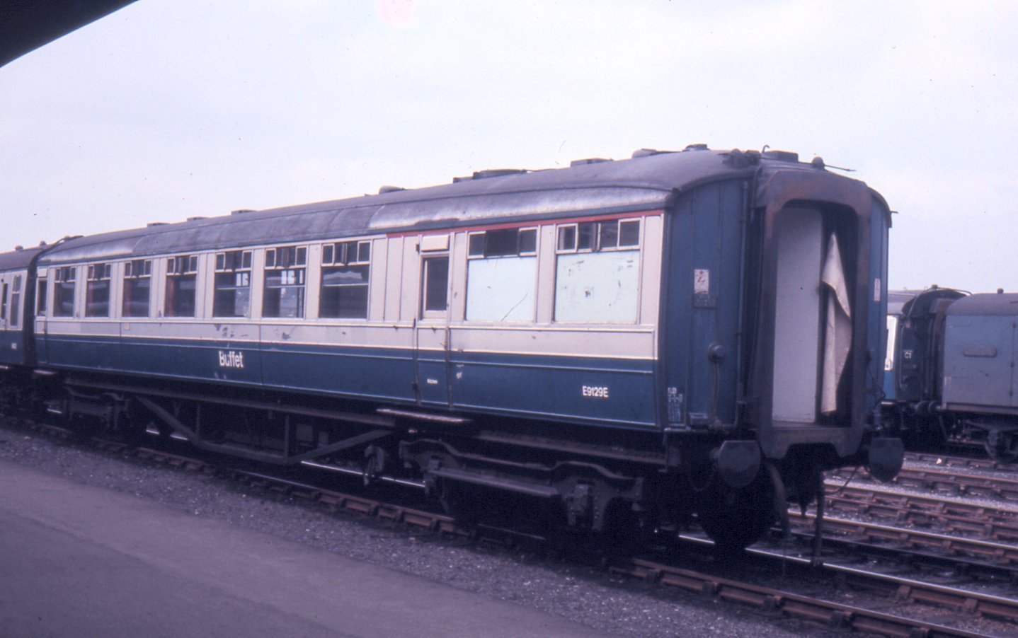
Gresley buffet website
Gresley Buffet Cars in the 70sI realised last night that there is actually a Flickr Pool for all of the pictures of NE Buffet cars in Blue/grey, so if you need any reference pics...
-
Gresley buffet
Gresley Buffet Cars in the 70sAnother pic, this time E9129E at York in 1973 : http://www.traintest...sley-buffet.jpg & E9115E at Peterborough in 1976 :
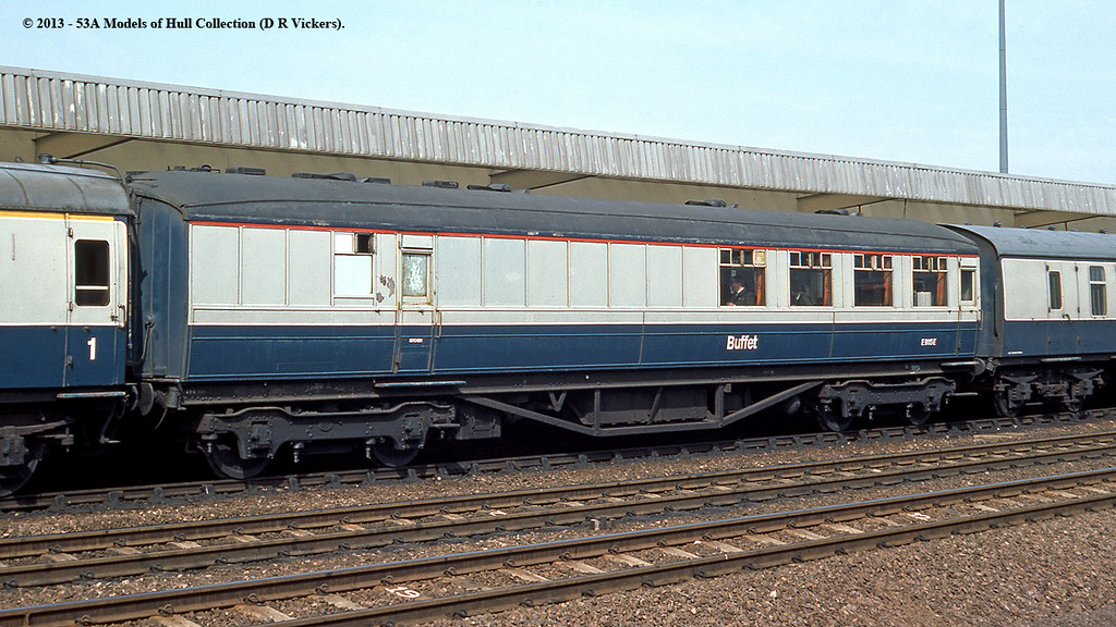
Phill :icon_thumbsup2:
-
useful relay circuit
Hericombe - 1970's Western RegionFiddle Yard Control Panel
I wanted the control panel for all of this to be easy to use and so designed it around route setting via diode matrices. This was a steep learning curve as I’d never done anything like this before but after much drawing of wiring diagrams and truth tables, it all came together in the end!
The panel includes a DC controller that's linked to the cassette road of the West FY which, via a rotary switch, can be set to DC, DCC, DCC Prog or an input for use with a Sprog II. It also includes a 5v output for the IR detectors mentioned above, created by adapting an off-the-shelf USB socket circuit, and a CDU for driving the Peco solenoid point motors.
To simplify the wiring (ha!), I decided to use a pair of Tam Valley 6 channel frog juicers for switching the polarity of all of the points in this area.
One of the more complicated aspects of the design was coming up with a circuit that would activate on the press of one button and then deactivate on the press of another. This was needed to drive the indicator lights for the route setting, as they required a constant feed in contrast to the pulse needed for the point motors. I eventually cracked this by using 12v relays in pairs (hidden under the panel with the DCC handset on above) like so:
This has not been without issue though, as time has shown that the relay coils don’t really like the voltages that come out of the controlling diode matrix and they’re starting to stick. This aspect is on the cards to be re-designed in the near future, possibly with solid state relays.
The face of the panel comprises two layers of clear Perspex with the mimic diagram between them. Set into the bottom layer are the 3mm flat top LED’s that are used to indicate the routes selected and various other functions. These are bright enough to shine through the paper of the mimic diagram but disappear when not in use. They look a lot brighter in the photo than in real life:
Operation is really simple: there are five possible routes in and out of the FY, selected by one of the five buttons in the centre. The route to or from a siding is then chosen by the button at the end of each. It all works very well although there are details that I’ve improved on for later panels. It may also get re-designed to accommodate different point motors as I’d like to move away from the solenoids at some point.
-
Charlton Bridge - 4mm BR(S) - Building Bridges
Charlton Bridge - 4mm BR(S) - Building BridgesAt the moment my focus is on the viaduct. The span is about 1.5m with a depth of about 200mm. Originally I had planned for this to be a standard brick arched viaduct of which there are numerous real life examples. I erected some plywood piers with the intention of covering with brick paper. This idea morphed into a girder bridge on brick piers and I spent a lot of time designing and then 3d printing the girders. This again gave me issues as the 3d printing warped and I found it difficult to get nice, straight girders. That was a long story and changing the type of resin in the printer helped hugely - but I was not 100% convinced I had the right look for the bridge. One of my issues was that I had laid a 6mm plywood track base and traditional sleepered track, whereas what I really wanted was the unballasted "baulk road" effect you see on girder bridges. I had also made the wooden piers too narrow and i needed to add extension pieces to widen it. All in all, I was not happy.
Then a friend visited and threw another massive spanner into the works saying that I had too many piers...
So yet another rethink.
This is the (rather embarrasing) current situation with the abortive 3d printed girders (all now scrap!), the ply track bed and the ply piers.
My new (and final answer) to this is to rip the whole viaduct section out and replace it with a structure based on Little Petherick Creek bridge on the North Cornwall LIne. Many pictures here.
I had amazing help from fellow RMWeb members who sent me drawings and pictures of the bridge. A lot of hours later I have drawn the structure in Fusion360 and i am now ready to start printing. Although based on the original bridge, that was single track and my bridge will be double line and my piers are much taller. But it will resemble the original.
here are the piers drawn up and ready to go. I will have a trial print tomorrow and see how it goes. Luckily I only need two sets - each one is going to take 13 hours to print!
I am still looking for pictures and details of the bridge if anyone else can help!
Ian


