

Pacific231G
-
Posts
5,955 -
Joined
-
Last visited
Content Type
Profiles
Forums
Blogs
Gallery
Events
Exhibition Layout Details
Store
Blog Comments posted by Pacific231G
-
-

This is very relevant to me just now because I need to take some photographs for publication of my own H0 layout and am not sure whether to simply use my iPhone (with a tripod rig) or to use my DSLR (also on a tripd) with long exposures (but I'm a bit limited on my smallest f stop)
Though it's slightly different from stills photography I found the same thing as Mike with my professional use of video cameras. Some years ago I needed to film various types of miniature (including built Airfix kits) for toy industry testimonials and, with a Sony VX1000 - a three 1/3" sensor DV "prosumer" video camera- I got far better results using that with supplemental macro lenses than I'd ever got from any TV film crew whatever lenses they used whether on 16mm film, Beta SP video cameras using 3 2.3" sensors, the then current format for most routine broadcast TV filming for TV was done on, or even the emerging Digibeta cameras (also with 2/3" sensors) though those did have a slightly higher vertical PAL resolution than the VX1000.
I always understood that it was the smaller sensor size that made that difference though for TV work you are far more limited with exposure times. The DV camera was also small enough to enable me to do things like filming on the footplate of narrow gauge locos that would have been close to impossible with a "full size" broadcast video camera.
I also find that at exhibtions I generally get better results with greater depths of field photographing layouts with my iPhone than with my DSLR (though possibly the iPhone's processor is just better at photography than I am!)
I have experimented with focus stacking but have beern advised by the editor of one of the major magazines that, for model railways, this is best avoided (or at least kept to no more than three planes of focus) as parallel lines tend to get distorted.
-
 1
1
-
-
 23 hours ago, PeterStiles said:
I've dumped the idea of delayed uncoupling and slapped three magnets in one for each siding. If this were a general purpose layout rather than an inglenook shunting puzzle I'd definitely have to look at alternatives.
I like the idea of an "uncoupling wand" tho'.
It's interesting (well maybe) that the Sergeant coupler used by some American modellers requires the use of a magnetc wand for uncouplig. Unlike Kadees and their clones, The McHenry coupler does actually work like a real AAR coupler with a steel ball inside the coupler instead of the coupler pin and, just like the real thing, the coupler heads have to be aligned. I guess they're the North American equivalent of using three link couplers to give operators that authentic switchman experience, except that for them the automatic model equivalent (from Kadee etc.) looks a lot more like the real thing than do our tension lock or hinged loops.
-
 1
1
-
-
I've had the same problem with delayed uncoupling with Kadees on my French H0 layout. I find that you can propel wagons a short way but eventually any slight jerk will generally cause them to recouple (so I tend to fly shunt them.) for coupling they also really need the whole length of both vehicles to be on straight track over the magnet (which mine aren't as I retrofitted it for magnetic couplers . for various reasons they don't seem to be quite as happy with four wheel wagons as they are with much longer American freight cars with trucks (bogies)
For H0 Kadee do make a manual uncoupling tool (mine is hiding somewhere) I don't know if Microtrains do an equivalent for N but I picked up a wizard wheeze from an American blog. Fine interdental brushes make very good uncoupling tools for H0 knuckle couplers so might be worth trying for the N gauge equivalent .
The ones I've used are made in Sweden by TePe (recommended by 94% of Dental Hygenists or so they say) and I think I got them from Tesco. They come in a pack of six with a single handle that the brush heads fit into and are obviously disposable for rheir intended purpose. As an uncoupling tool I'll probablty fit one of them to an old paintbrush handle but so far have just used one of them as sold.
They're worth trying and, if they don't work in N gauge, you can always use them to clean between your teeth (as recommended by 94% of Dental Hygenists10
Apparently, a lot of American modellers- where Kadees or their clones are almost universally used- have abandoned the magnets. They do their uncoupling manually- just like a real switchman- as they follow their "peddlars" (pick up goods trains) from depot to depot around their basement empires. for appearance sake some of them even cut off the trip pins.
-
 1
1
-
1
-
-

Not exactly cross-London but one of my favourites was the GWR's Ealing and Shepherds Bush Railway from Ealing Broadway to a terminus close to the Central London Railway's then Shepherds Bush terminus. It was intended to provide a better link to the City for commuters than via Paddington and would presumably have been a secondary suburban terminus for the GWR. In the end, once the CLR had abandoned its plans to sweep around to the South and onward via Hammersmith, the GWR and CLR decided that an interchange at Ealing Broadway would be better and offered running powers to the CLR over the ESBR via a link north of the CLR's later terminus at Wood Lane to the GWR line which also connected (as a goods line) with the West London Extension Railway. This was actually delayed by WW1 and didn't open until 1920. It is now of course the Central Line with a branch, alongside the former GWR cut off main line towards Banbury, to West Ruislip but several of its stations have a decidedly GWR feel to them.
-
1
-
-
Hi Dave
Not having room for pointwork for my fiddle yard I'm looking at traversers, sector plates or cassettes. They'll need to be about 1.5m long with four or five track to accommodate a four coach plus brake van train comfortably so I'm wondering how long the traverser on your layout is. I want to be able to set up the yard for an operating session and then not have to constantly be working in the fiddle yard between trains.
-

Many thanks Ben
Champagnole 141Ps are only worth about £70 at the moment and I have at least one other (I have far more locos than I need!) The motor and pick ups are of course in the tender and that's fine. In fact I've just paired it with a tenderless 241P (they used the same tenders which had their own numbers) though the shed names don't match. It's odd though because it was fine when it last came out of its box. However 241Ps are a bit long for my proposed Les Minories Francaise (possibly an enlarged Saumur Etat) the extra inch over a Petit P (141P) or a 231K really does make a difference and the latter look a bit less silly at the head of a four coach rapide.
The non self-loading goods are likely to be handled mainly by Lilliput 140Cs and Roco 040DEs (currently masquerading as Ep IV BB 63000s) and an 040B that's somehow wandered from the Est to Ouest/Sud Ouest
-
3 hours ago, readingtype said:
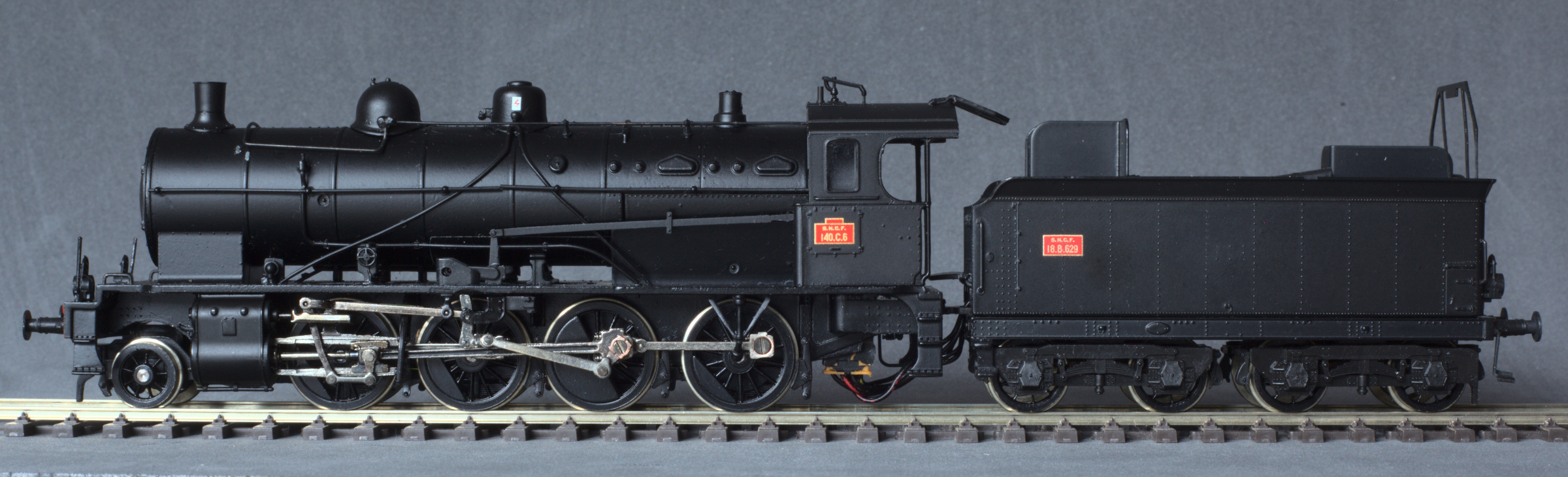
I thought I would push the wheel question further and sent 140.C.6 to Holger Gräler in Germany. Holger has previously worked wonders with the wheels on my Roco ÖBB Reihe 93, by replacing the tyres and retaining the original wheel centres and rims. The Reihe 93 has plastic wheel centres. The 140.C has cast metal wheels and these have come back looking absolutely super. The carrying wheels and tender wheels are new.
I now have no reason not to investigate what can be done to tidy the model up -- for instance, the box under the cab is a Liliput invention that holds the tender drawbar and at least one modeller has found a way to do without it. The electrical connection also needs thought. The space beneath the frames under the cab should be basically clear.

I'd be interested to know more about Holger Gräler. A driving wheels has just fallen off the axle of one of my Jouef (Champagnole) 141Ps and it was fine when I cleaned and tested it a year or so ago. I think the plastic bush may have perished.
-
 3 hours ago, Ian Simpson said:
Thanks, @Pacific231G. That's a great website (although I was shocked at my geekiness when I realised I went to the Paperwork section first).
Don't worry. I just spent an hour trying to figure out which end of French mixed trains the passenger carriages were marshalled. The answer was that it all depends though I assume that in Britain, with our strange affection for unfitted-loose coupled wagons, they were always next to the engine.
-
1
-
-
I've been looking at some photos of stub switches on D&RG RR and on simple turnouts the moving rails slide on plates that limit the travel with the tie bar assuring the alignment of the opposite rail. At any rate that's what I think I'm seeing but the images are here.
http://www.drgw.net/info/StubSwitch.
-
1
-
-
Very nice Ian
Apparently, the reason stub switches lasted for so much longer in N. America was because they weren't prone to getting blocked by snow (though extreme expansion in hot weather could be a problem. Their limitation was, as you say, that they were not good with high speeds or heavy axle loadings. They were used on some narrow gauge RRs in the USA until quite late but I don't know how late they were used industrially in the UK.
-
1
-
-
On 15/05/2020 at 20:32, Ian Simpson said:
Many thanks, @Pacific231G, the "Informative/Useful" button doesn't do justice to such a fascinating answer. I'm always intrigued by your explanations of early French practice, and I had absolutely no idea that the "restrictive" approach to signalling lasted so much longer in France. I've definitely learned something new today!
They still use open block, a block is open for a train to enter unless it's occupied or closed for some other reason. The main effect of that is that the block post behind doesn't have to offer a train to the block post ahead though, once a train has entered and occupied the section, the post ahead has to confirm that it's passed before it can be cleared. But, if you think about it that's how automatic four aspect signalling works in Britain. After a train has passed, the signal goes red, then yellow, then double yellow then green as it moves away section by section.
-
1
-
-
2 hours ago, Ian Simpson said:
Yes, that must have been a big improvement - and it would be an easy feature to add to the model.
I think the Great Western adopted the safer disc and crossbar design fairly early, while the London and Croydon soon became a pioneer of the semaphore signal.
I think French and Belgian railways still used rotating signals into the 20th century, and I'm not sure that they had cross-bars. If not, I'd be interested to hear how they provided a definite signal that the road was clear ahead.
French mechanical signalling has always been based mainly on rotating signals though block signals were semaphores. I don't think much of it is left now (though there are some carrés- absolute stop signals- in use on busy days on the Baie de Somme) but colour light signal indications still retain the names of their mechanical equivalents.
If you want to see an example of the first fixed signals used in France you'll find it at Didcot in the broad gauge area! GWR disk and crossbars introduced in 1843 by the Paris-Orleans Railway's senior materials engineer named Clarke and as on the GWR the crossbar indicated danger and the red disk clear. These were used by the PO until about 1850 but the Paris-St. Germain railway adapted it to a red disk which was a stop signal operated locally by a gardien. These and the other rotating signals soon introduced didn't have a crossbar or any other indication that they were open apart from the signal lghts that indicated their state at night. The PLM introduced sémaphore signals based on, or at least inspired by, those developed on the London and Croydon and these became the block signals used generally. So, with French mechanical signalling, sémaphores were (and are) block signals indicating the state of the block ahead while the absolute stop signals protecting against conflicts, at junctions for example, speed restriction signals, and the advance warning signals for all of these were rotating signals with differently shaped and coloured targets to indicate their meaning.
Though it started from the same early British technology, signalling in France developed on different lines. British signalling is permissive-a driver has to have permission from a clear signal before entering a section of track. French signalling is restrictive. A driver proceeeds according to their train order until a signal gives a restrictive indication (that wasn't quite the same on single track lines) This meant that drivers did not get a definite signal that the line was clear ahead and with rotating signals, if the target wasn't visible there was no restriction. The French also use open rather than closed blocks- a train is clear to enter a block ahead unless it's occupied. This makes it far easier to close block posts at quiet times and station masters, who were generally responsible for signalling at smaller stations. didn't have to be constantly present at their block instruments.
When the new Verlant signalling code was adopted in 1936, it called for signal lights on mechanical signals, previously only lit at night, to be electric, permanently lit and colour light signals gave the same colour indications as lights on mechanical signals. Needless to say, with CLS (signalisation lumineux) the lack of any indication is taken as a closed signal (as it would be in Britain) so in practice the use of signals is not now so different.
-
3
-
-
That's gorgeous.
I actually had to check that it was 4mm rather than 7mm scale.
Very well done.
-
 1
1
-
-
Slightly off-topic for China Clay but I think this is a problem common to including most rail served industries in our models. From docks to steelworks, if they warranted private sidngs at all, they tended in reality to completely dwarf the goods trains serving them.
This was brought home to me a few years ago when I found a real (though disused) yard in the small village of Valmoint in Normandy. It consisted of a headshunt and two sidings each with a capacity of no more than three four-wheel wagons. The rail yard itself was small enough to be modelled at full size and I envisaged this as a sort of double inglenook Microlayout.

I came up with this microlayout with almost no compression of the trackwork

The local TOM (Train Omnibus Marchandise i.e. pick-up goods train) would shunt the station sidings, picking up or dropping two or three wagons for the silos after which the points could be set to protect the main line. Shunting could then proceed within the private yard (the real Valmont was worked by capstans though I envisaged a small four wheel petrol shunter) while, if fiddle yards were added at both ends, other trains passed by in the foregound.
However, when you actually looked at the size of the grain silos that this tiny yard served.


They were comparatively enormous and this was among the smallest of these local co-operative silos; most of them would run almost the entire length of a station.
Similarly, you didn't really get sidings serving fish docks large enough for just one trawler, general docks with room for a single Clyde puffer, or tiny brickworks.
Though it's probably not your era, did any of the china clay works use narrow gauge railways to load straight into main line wagons or would the standard gauge siding always be alongside the dries?
When I was in Plymouith in the mid 1960s I seem to remember the dries at Moorswater as beng comparatively small. However, my interest there was traces of the Liskeard and Caradon so I didn't pay too much attention to the China Clay set up.
-
3
-
-
Mine were new but haven't done that much work yet (my layout is quite small) so I hope your experience doesn't represent my future ! Perhaps you just got a "Friday afternoon" example
-
i think you've been unlucky. I have three of these (different numbers), all bought for less than half the RRP as imperfect returns from Bachmann's stand at various shows, and they run really well. Mind you, I think the returns did get checked before they went back on sale and the "faults" were minor cosmetic ones. In one case the packaging must have rubbed a tiny bit of the paint off one of the domes' Easily fixed with a black marker f I can actually find the fault.
Here is 1-140C6 shunting the winery's private siding

I know what you mean about small easily broken details. My least favourite job (with rollng stock fitred with NEM pockets in general) is removing the oriignal couplers to fit Kadees. It always feels like trying to remove a bee sting without killing the bee. My other steam power for my current layout is a (new) Piko 040B from whatever they called their basic/junior/railroad range and it's a perfectly good scale model but a bit less detailed so I'm happy to use it for ordinary operating sessions. I do sometimes wonder whether scratchbuilding with brass would actually make operating less stressful.
Here are 140C6 and 040B315 together on the layout and I'm not that conscious of the ex Prussian G7's lack of detail.

I've long felt that there was something a bit fishy about the ALVF (Heavy Railway Artillery) orders built by North British as don't think any of them were ever actually used to pull heavy rail guns around. The "official" explanation was that they wanted to avoid steam locos near the front giving their position away but by 1917 they'd have known that. Given that they were promptly "loaned" to thethen still private mainline railway companies who were hauling a lot of extra goods for the war effort, I suspect that this may have been a way for the goverment to supply additiional motive power to private railway companies without actually breaking any rules.
-
3
-
-
2 hours ago, Ian Simpson said:
Thanks for such a full and fascinating post, @Pacific231G It really deserves a much wider audience than the handful of people reading my blog. The distance-between-towns explanation seems very reasonable to me! And I agree the atmospheric system was more successful than we often remember today.
@Rockershovel, that's a good point about the weight distribution of Norris's design taking care of itself. As Pacific231G pointed out, the 4-2-0 arrangement is basically a three-legged stool if you are using a leading bogie. Norris's concept was widely copied by other US builders. I wonder if the reason British engineers didn't do the same was the poor performance of the Birmingham & Gloucester own Norrises, which as far as I can see had nothing to do with their wheel arrangement and everything to do with their inappropriate materials for British conditions and with the inexperience of the British enginemen.
Thanks Ian
I've always understood that the three legged stool principle applied equally to the American 4-4-0 type familiar from hundreds of Westerns*. It surely must have done for them to stay on the apalling track originally laid by the UP. I don't know whether 4-6-0s built on the same principles retained the same ability to handle rough track.
*The locos starring in Westerns were often one of three Virginia & Truckee 4-4-0s Nos 11, 18 & 22, bought by Paramount, MGM, and RKO between 1937 and 1947 (they also bought V&T no 25 a Baldwin 4-6-0) However, the single loco that seems to have appeared more often than any other has been Sierra RR no 3, a Rogers 4-6-0 that has appeared in over 300 movies and TV shows from the original High Noon to Petticoat Junction. The Sierra RR had unusually short carriages which is often a giveaway.
-
1
-
-
On 22/02/2019 at 20:00, Ian Simpson said:
Thanks, Nearholmer and Northroader, the weight / springs / adhesion points are very interesting. A lot of the weight did fall on the Norris's driving axle, which helps explain the design's good performance on demanding gradients.
So considering Pacific231G's point, were early French lines generally less demanding in their requirements than British ones, I wonder? (Other than the very steep St Germain line with Samuda's atmospheric system, of course.) I've always assumed they were pretty similar, but that's just my lazy assumption because the same engineers, like Locke, were laying them out.
Sorry for the long delay in responding to this.
I agree that Norris's adoption of a 4-2-0 wheel arrangement to cope with roughly laid American track on the three legged stool principle was for totally different reasons than Crampton's and led to the classic "American" 4-4-0 arrangement.
Apart from the very early St. Germain* and other Paris local lines I think the major difference was always the generally longer runs between population centres in France often on relatively flatter ground. That probably made continuous running at speed more important than accelaration (which also led later to a greater interest in compounding by French loco engineers)
Crampton had of course been a GWR engineer and, while working with Gooch on his successful large driving wheel broad gauge loco, conceived the idea of getting the same broad gauge advantage of stability at speed on standard gauge railways by achieving a low centre of gravity with a large driving wheel. The reasons why his locos were more successful in France and Germany than in Britain may though have been as much to do with his general understanding of the value of larger steam passages, heating surfaces and bearing surfaces, as to his actual patented wheel arrangement.
France's early railways did draw very heavily on British engineering as evidenced by their running on the left and widespread use of double champignon (bullhed more or less) chaired track. However, quite apart from the Brunels, it was by no means a one way traffic The multiple tube boiler was invented by Marc Sequin in 1828; the mechanical semaphore (and the name) was developed by Claude Chappe but Britain's railways came to adopt a simplified system of moving arms for almost all its signalling.
Ironically, France's use of rotating targets for most signals, seen as very foreign by many British observers, actually came from the GWR. In 1843, The Paris-Orleans simply adopted Brunel's disk clear and crossbar danger signal (I think their engineer had come from the Great Western). In 1845 Benoit Clapeyron, in charge of traffic on the St. Germain and Versailles line modified it to a simple red disc that was presented as a stop signal for five minutes after the passage of a train then rotated to not face the driver when the line was considered free. The "disque" was widely adopted by othe railways (though its meaning changed as other targets were introduced) though the PLM had a very British looking three position semaphore (danger, caution, clear) until 1885 when a national signalling code was adopted and movonmg arm signals were confined to direction indicators and sémaphores which are non absolute block signals.
*The St. Germain line, France's first steam hauled and passenger railway, was fairly flat without undue curves from St. Lazare to its original terminus at le Pecq. The limited power available to early locomotives meant that the final two kilometres up to St. Germain itself, requiring a curved route with a 3.5% gradient, was only made possible by using Samuda's atmospheric system which could haul a train up the gradient at 35km/h (return was by gravity) . The extension opened in 1847 and, with the odd glitch, operated satisfactorily for twelve years as an atmospheric railway until more powerful locomotives became available. Even then, trains had to banked up the gradient until electrification of the line was completed in 1927. I've always thought that the successsful use of atmospheric power on this line gives the lie to the popular view that it was Brunel's great folly. Brunel was not though a good locomotive engineeer so may have underestimated how rapidly the development of steam locomotives would make it obsolete.
-
3
-
-
15 hours ago, Ian Simpson said:
Thanks for a very interesting comment. I'm not sure how far Crompton was inspired by Norris's locos, but he can't have been unaware of them. There is one noticeable difference between the two engineers' locos: on Crampton's designs the driving wheels tended to be large for speed, while Norris's drivers tended to be small for power. The Birmingham and Gloucester Railway used its Norris 4-2-0s to haul freight trains up the Lickey incline, but it used more traditional British 2-2-2 with large driving wheels for its express mails.
BTW the forerunner of the Norris design is Edward Bury's small bar-frame locos, as used on the London & Birmingham, London & Southampton, Liverpool & Manchester, etc. William Norris nicked Bury's design, beefed it up a bit and replaced the front axle with a bogie to cope with the roughly-laid track of the early American railroads. Bury tried to sue him in the US courts (Norris was based in Philadelphia) but lost.
Yes, in the late 1830s and early 1840s British, European and American railways are using very similar designs, mostly British as you say. And the British companies all tended to buy standard locos and stock from a few commercial builders, so that most early models can be used in a range of settings. For example my own little layout could represent a small branch in New England or southern Austria just as much as one in Gloucestershire
Thanks Ian
Looking at it again, I think the Norris 4-2-0 locos were perhaps more the forerunners of the classic American 4-4-0 arrangement with the same "three legged stool" principle that could, along with bogie rolling stock, cope as you say with America's more roughly laid track.
Looking at its first railways, most of the first earliest locos in France used the same 2-2-2 wheel arrangement as Britain (Der Adler might be a useful starting point but I notice that the Trix/Maerklin set relies on an electrical connection between all three carriages to provide pick-ups for the mechanism located I think in the leading carriage; not so useful for shunting)
By moving the single driving axle behind the firebox the Crampton design enabled it to be much larger, while still having a low centre of gravity.

It's not very clear why Thomas Crampton's patented arrangement was so much more popular with railways in France (127) and the German states(135) than in Britain (51) though longer runs between stops may have had something to do with it .
-
2
-
-
A fascinating project Ian. I also didn't know about the Bachman US products nor that locos were imported to Britain from the USA that early.
Were the Norris locos precursors of the Cramptons (where the driving axle was behnd the firebox) ?
In general, going back that far "early British railways" can rather mean early ralways full stop as the same British technologies appeared elsewhere in the world before practices started to diverge. I happen to be interested in French railways (so H0 is already a given and I agree about the low slung boilers emphasising the narrowness of OO track) where British practice seems to have had a longer influence than in the States (left hand running, bullhead rail. side buffers etc)
In the 1840s the few railways there were even more British. For example, Joseph Locke was the chief engineer of the Paris-Rouen railway opened in 1843 and Thomas Brassey its main contractor, the very first railway signals in France were GWR disk and crossbars, and there was even an atmospheric railway. It used the same Samuda system that Brunel couldn;t get to work properly and worked succesfully for thirteen years from 1847-1860.
-
1
-
-
Going into a pub may be misleading. Pub interiors, even the "authentic" real ale variety, do look very different now from how a pub on the corner of a terraced street would have looked in the 1950s. Here Google is your friend, just do an image search on Pub interiors 1950s (or whatever era you're in) and choose the most typical looking examples to give you more than enough information to model them. Don't forget the kids sitting outside with a bag of crisps because "family friendly" was still in the future.
I had the same problem with my Café de la Gare. I started to put in banquettes, just like in most French cafés, brasseries and bistros I'd ever been in, only to discover that in the 1950s-1960s they were far more likely to have smallish tables with individual chairs which are a lot more work to model. They also of course look totally different around meal times than at times when everyone is drinking, chatting or playing cards
It's always difficult to know how much detail to include in interiors, An empty space just somehow looks empty but it's easy to include far more detail than anyone is ever going to see. it depends a bit on whether you intend to light them and of course if you actually enjoy modelling interiors.
you could argue that all you're really interested in is what you can see with your eyes (not a camera) from outside at the equivalent of a normal viewing distance- which I'd suggest is the other side of the street- or better still from the top deck of a bus passing on the other side of the road. That won't tell you what's authentic for your period but it might give you an idea of how much you can (and can't) see.
-

I used Fulgurex motors on my H0m layout but am not very impressed with them. They're incredibly noisy, don't seem particularly well built and, because they can barely throw my Tillig points, need to be very carefully set up. The point blades are not hinged, which was why I opted for a motor drive to avoid excessive force on the tiebar. The force needed to throw the point blades throughout their travel means that there is no overrun when the motor is cut so the spare switch used to power the frog has to be set up to switch before the one that controls the motor. This doesn't always work which led to shorts or, when I rewired them to use both spare switches (one at each end) as on-off switches, to reliance on blade contact to power the frog.
I did install them as per Fulgurex's instructions with a torque tube but there is a lot of mechanical loss in this and a more direct drive to the point blades would probably work better.
-

This looks great Nick and I like the idea of individual scenes- that tends to be how we see the real thing at close quarters. How did you use the hanging basket liner? So far as I can tell there seem to be three methods one where you pull it off its backing and glue the tufts onto a bed of PVA, one where you just glue pieces of the whole thing base down and one which I'm just about to experiment with where you lay it face down onto PVA spread on the prepared and painted base and then pull off the backing when it's set rather like the Peter Denny method with dyed lint which I used to use years ago.
Look forward to seeing the next sections.
David


When is good enough good enough? Improving the Bachmann 93xx
in Barry Ten's Blog
A blog by Barry Ten in RMweb Blogs
Posted · Edited by Pacific231G
Worth noting that this seems to have been the philosphy adoptet by John Ahern and Peter Denny, in their cases of course with models they were buiding from scratch. Once they'd reached a standard they were happy with, everything they subsequently built fitted with everything else and neither of them threw much if anything away (though presumably some models went wrong and never saw the light of day.) The result is that both their layouts (happily still with us) work as a complete picture.
I think you can compare that with other arts and, if you see the model railway as a complete scene, rather than as a stage on which to view superdetailed models of rolling stock (which clearly some people do and that's fine) then a level of consistency is important. This isn't just about the level of detail. I've found with the buildings on my own layouts (and I have no pretensions to fine scale perfection) that those built from plastic, those built from card and those moulded from plaster or resin, just don't look well together. It's not that one if inherently "better" than the others but, a bit like water colour and oils, they are different media.
There is of course the factor that a model you've built yourself can be far more satisfying than one you've simply bought.