


irishthump
-
Posts
53 -
Joined
-
Last visited
Content Type
Profiles
Forums
Blogs
Gallery
Events
Exhibition Layout Details
Store
Posts posted by irishthump
-
-
Beejack, thanks a million!
I'll give that a go tomorrow and report back,
-
Thanks RAF,
Here's the best pic I can get of the back of the pcb.
Pin 1 is on the top row right as you look at it.

-
Guys, any help with this would be greatly appreciated.
I have a Hornby class 56 PCB which I'm planning to use in a kit built loco but I'm not sure which terminals on the board to solder to for directional lighting.
Here's a photo of the board:
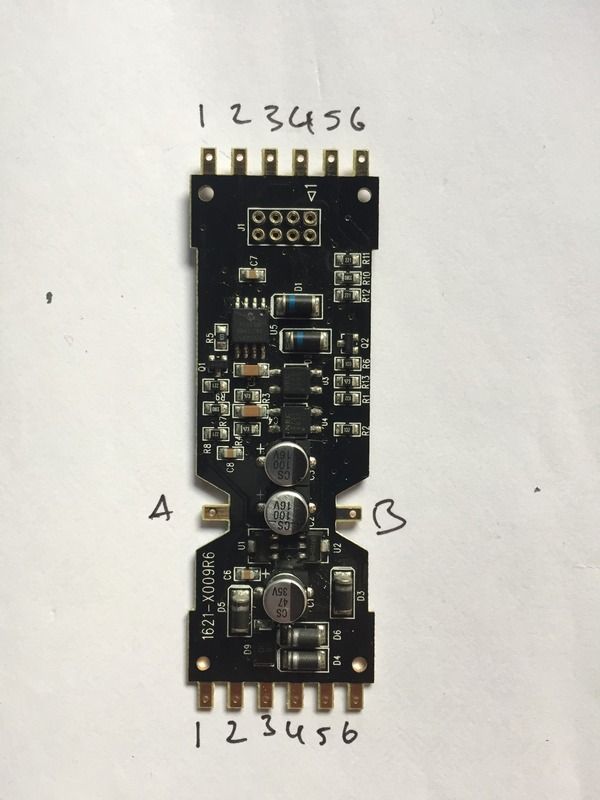
I know terminals 3 + 4 are for track power and A + B are the motor connections, and I'm pretty sure 6 is the common. Would any of you guys know which of the remaining terminals correspond to decoder lighting functions.
I haven't had any luck with searching the web and the Hornby service sheets for the class 56 have no info on lighting functions.
-
I imagine these are very similar to the decoders found in the Bachmann US Soundvalue locos?

Directional light wiring on Hornby PCB
in DCC Help & Questions
Posted
Beejack, thanks once again, that did the trick.
My problem stemmed from the fact that the PCB has the negative as the common. I had put together 2 small PCBs with surface mounted LEDs for the head/taillights but I had wired these with a common positive.
Thanks once again for the help!