


davelester
-
Posts
97 -
Joined
-
Last visited
Content Type
Profiles
Forums
Blogs
Gallery
Events
Exhibition Layout Details
Store
Posts posted by davelester
-
-
On 15/10/2020 at 22:31, Rob Pulham said:
I must admit that this is the aspects of modelling that I enjoy the most.
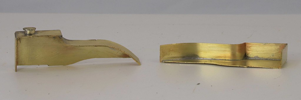
Well, in that case, Rob, I offer the following details of the snifting valve from Isinglass Drawing #301 (for the Gresley J6).
For the LNER snifting valve we have the dimensions:
- Base plate 12 3/4" square, and 3/8" thick.
- The dome of the valve cover is actually made of 1/4" brass, and is separated from the base plate by 3/4" gap; note that this gap takes account of the boiler/smokebox curvature.
- The dome is of 10 3/4" diameter.
- The height of the dome (without the nut on top) is 3 11/16" above the 3/4" gap on the boiler centre line.
- Finally the dome itself has a radius over the top of 3' 2".
Obviously, there are additional details that I don't have: the radiusing from vertical sides to dome (1/4" radius?); the size of the retaining nut (1 1/2" AF?); the positioning of the bolts for the base plate (8 bolts in noughts and crosses pattern for sure, perhaps on 5" centres?); the diameter of the valve under the cover (8" ?); and the number of holes in the side of the valve (12? 16?). Maybe Mr Trice has some nice photos of the snifting valve to allow us to tighten up my guesses?
One note: the original GNR version was still on some J6s in BR days, and differs by being flatter, and having a more curved top. Thus:
- The height of the dome (without the nut on top) is 2 11/16" above the 3/4" gap on the boiler centre line.
- Finally the dome itself has a radius over the top of 1' 4 1/2".
- The nut on top looks to be bigger.
[Edit: The photo of 64206 mentioned on page 1 of the thread at Hitchin in 1960 shows the GNR snifting valve cover.]
-
 1
1
-
4 hours ago, Rob Pulham said:
The next task is to cut out the firebox top so that I can mount this in place - I may need to trim the mounting plate as I had cut it big enough to hold while drilling all the holes with my pillar drill.
That is a simply stunning piece of work, there Rob! Well done.
-
 1
1
-
-
20 hours ago, Rob Pulham said:
Brilliant, thanks for taking the time to look Dave.
I have the GNR Engine sheds series and have had a look (page 38 for anyone else wanting a look).
I can see the seam on the firebox top but I am missing the anti glare fixings (I am not sure what I am looking for). I haven't added a seam on the cab top yet so I will remove that from my to do list.
I note that the Ross Pops are sat on a plate ringed with studs/nuts below the cladding so that's another little job.
There's a series of studs(?) or catches across the roof top of the nearest J6, about halfway from front to back.
And you did notice that plate at the back of the cab roof, yes?
-
On 12/10/2020 at 12:44, davelester said:
The most memorable photo of a J6 cab I know of is one with "Robert the Devil" charging towards a stationary J6 in 1927 (possibly LNER Goods Traffic, Wild Swan, possibly at Sandy) -- I'll look it out later on -- but I need to make the most of my last day of freedom here in Manchester before lock-down to get a load of ply cut for base-boards.
I've now looked this image out, and the cab internals are not showing. (It was Sandy, and was the Wild Swan book).
For roof details on J6's, volume 3 of GNR sheds has a post-war picture of Bradford (Hammerton Street) Shed. I cannot see any sign of the join on the roof, so I hope you haven't put it in yet.
But there is a line along the top of the boiler just to the left of the safety valves on the first section of boiler cladding. There are also rivets holding them together. Plus fixings for the anti-glare covers used in WW2.
-
1
-
-
6 hours ago, Daddyman said:
Neither Locos Illustrated nor Yeadon show the stop on K2s in GN days - but I have no books containing pictures of GN Atlantics. One photo of a K2 with the stop in LI is dated 1934, and they appear more and more in the 1930s shots. However, given that some West Highland K2s arrived with the stop already fitted, that would suggest it started to be fitted before their 1933-4 move to Scotland (I can't see Cowlairs making the same stop as whichever shed maintained them in the south). Some K2s also had the stop incorporated as an extension to the hinge straps as on the V2 above.
The same appears to be true of the J6's: no GN period modifications, but an increasing number starting from about the late 1920s.
By the way, there is an excellent photo on alamy.com (image id PAPE4C) of the preserved N2 1744, showing this stop in significant detail. I'm unsure about the propriety of linking to commercial images, so you'll need to go to the site and enter the details I've given into a search.
-
1
-
-
On 10/10/2020 at 17:14, Daddyman said:
It's the doorstop, isn't it? Found on many GN doors. Maybe try other Yeadons for a better view? - K2s, N2s, etc.
I've just looked at the V-2 GA from 1936, and there's no door-stop. Could it be that this is a post-war, or BR addition?
If so -- as I model the pre-war LNER -- this probably explains why I've not previously noticed them.
-
17 hours ago, Rob Pulham said:
Thanks Dave,
I may just add a score line down the middle of the roof to imitate the seam.
I also looked for the height of the floor in the middle: it's 10" above footplate level, and the fall-plate is hinged from this. Obviously the tender would have the same height floor added.
I looked to see what height the internal splashers were on each side of the floor, but the GA doesn't show this. It also doesn't show any seats.
The most memorable photo of a J6 cab I know of is one with "Robert the Devil" charging towards a stationary J6 in 1927 (possibly LNER Goods Traffic, Wild Swan, possibly at Sandy) -- I'll look it out later on -- but I need to make the most of my last day of freedom here in Manchester before lock-down to get a load of ply cut for base-boards.
-
1
-
-
20 hours ago, Rob Pulham said:
When you say that there was a seam at the top do you mean in the middle of the roof?
That's just right Rob. But it's nearly invisible.
I was thinking along these lines to ensure that handrails and cab cut outs lined up on each side.
-
Ahh, that side!
Nothing at all on GA.
And the differences on your photos suggest that this is something added in an ad-hoc fashion.
-
 1
1
-
-
On 09/10/2020 at 11:52, mikemeg said:
Dave,
[nice phots omitted]
I had a look yesterday at Yeadon for any indications about the smokebox door stop -- as the GA has the right hand side of the front aspect half-sectioned.
I could be wrong, but from photos it looks more like a small "ball-like" knob screwed in from behind. Imagine a miniature handrail knob without the hole.
-
1
-
-
4 hours ago, Rob Pulham said:
Not much to show for two evenings work, but I have completed the sandboxes.

Rob,
That's a good job on the splasher/sandbox!
Three points about the cab:
- The cabs for 601-610 (GN numbers; add 3,000 for early LNER numbers) have a slightly higher cutout and 3" higher horizontal cab handrail. This is because they were skip-looted at Doncaster from scrapped A4 Ivatt Singles.
- As usual -- for the GNR -- there is beading on the inside of the cab all the way around. Also, as usual for Doncaster, this beading is a squashed half-round section, 2" wide and 5/8" high.
- I have the 4mm version, and found it difficult to get the cab sitting correctly. I'm now considering building it as a separate unit, and then screwing or soldering to the footplate and boiler. You can use a base plate since the actual cab floor is raised above footplate level. Also, note that the real cab side sheets were constructed in two parts with a seam at the top.
-
1
-
38 minutes ago, Daddyman said:
Is the backhead similar at all to another loco available RTR - the A3 or A4, for example, to save you some trouble?
Not really.
Gresley wide firebox boilers were straight-sided (at an angle!) -- and with a diameter of 6'5" where the firebox joins the coned section of the boiler.
The Ivatt boiler is 5'6" in diameter, and the firebox has curved sides
-
14 hours ago, k22009 said:
I've a small pile of detailing parts to make up so i thought i'd start with the basic backhead, cab floor and steps. The backhead will have pipes, fire door, gauges etc added once i've digested an enlarged print of the Isinglass drawing.
Perhaps this will help....
... note carefully that it is a GA, and thus represents an "as intended to be built" condition. I think the water-level gauges, at least, will have been updated in the 1920s.
-
1 minute ago, Daddyman said:
Shouldn't the corners of the flare be curved? And the tender body too, for that matter? Or is that a different tender type?
Yes.
All Ivatt tenders have a flare on the top plus curved ends to the tank (and thus 3D curved flaring).
Most of the tenders attached to the C1s will be self-levelling with 6' + 7' wheelbase -- as drawn.
A detail to watch for is the beading (2" x 5/8" elliptical), which is on both sides of the front part of the sheeting -- just as it is on both sides of the cab sheeting. And some tenders had matching cut-out handholds.
-
1
-
 1
1
-
-
Dave,
If you want the official GA drawing, it's currently on sale from the NRM.
-
1
-
1
-
-
1 hour ago, MikeTrice said:
You are correct regarding the more vertical aspects for the brake end. Best illustration is the attached image. Note that the lower curve is the same for both ends but as you say the upper panels are more upright:
Thanks very much indeed. My guess would be that you made the MJT ends for the later standard 9'3" stock, yes?
-
1 hour ago, MikeTrice said:
From drawing 102E:
Thank you very much indeed Mike!
It makes interesting viewing since in a chat with Danny Pinnock many years ago, he suggested my use of a three-arc roof on my orchid van drawing (an interesting 1896 item of NPCS) -- made by guessing from the Diagram Book drawing -- should have been elliptical.
-
2 hours ago, MikeTrice said:
Mike,
How does the brake-end differ from the standard 9'3" end you've shown us? It's not just a slimmed down version is it? My hunch is that it stands more "vertical".
Does the early LNER 9'0" stock look similar? The underframe would be identical in width, so again, I think the sides look less bulged, and more "vertical". Is that right?
Finally do you have anything on the GNR Howlden non-bogie non-gangwayed roof and/or end profiles? If it's too much trouble, I'd instead appreciate the NRM drawing reference -- though when we get a chance to order them again would be anyones guess!
-
4 hours ago, 30368 said:
Thanks Daddyman. I am not too bothered with the surface marks on the boiler - by the 1950's these were fairly old loco's and despite new boiler cladding being fitted from time to time would be fairly "rough". That is not an excuse for shoddy workmanship!
Could I suggest some alternative methods to remove excess solder?
- To get rid of large blobs, try using a solder sucker (example here); care's needed to not take off components you've already soldered.
- Worth a thought, though I don't usual use it, is braided copper -- a bit like scaletrix pickups (youtube demo here).
- A bit brutal, but very effective are PCB cleaning tools. I have one tool which has one end like the top right, and one like the bottom left (the link items are expensive, so shop around: amazon link to show shapes); and finally:
- Use a piece of scrap etch -- from the kit you are building. Provided it doesn't get work-hardened, it will be precisely the same hardness as the kit you are building, and won't mark the surface. One quick hack is to put the scrap etch into a pin-vice -- this makes it much more comfortable to use -- and is safer as well.
Of course one way to make all this easier is to not put so much on in the first place! I do this by tinning each component, and then holding the components together, with flux between them, and heating.
Hope that helps,
Dave
-
2
-
18 hours ago, Blandford1969 said:
What a lovely model this has turned into. The cab looks good. A daft question, I thought the K2s had a vertical screw reverse like the Pacific's?
The GA Drawings I have show the type of reverser Richard has built.
I'd be surprised if anyone thought it worth changing this item; Doncaster was always running on a very tight budget.
Dave
-
1
-
-
On 02/03/2016 at 21:57, MikeTrice said:
It has been parked for the moment as I had to wait for some bits to arrive and I went on to other things in the meantime. Really must get back to it.
Mike,
I've been looking at doing this train. So, is it still parked?
I seem to recall you mentioning something about the Isinglass drawing errors. I know about the 10' bogies, the roof vents (both thanks to you and your postings) -- but I thought you'd mentioned the windows, and there's clearly something wrong with the canvas sheeting between vehicles!
Dave
-
19 hours ago, 30368 said:
Working on my layout (70D) so progress has slowed a bit. Cab now fabricated and fitted to the footplate. I assembled the two sides and cab front first and chaecked for alignment and squareness before soldering to the footplate. Poor pictures I'm afraid.
Richard,
Here is a photo of the cab of Loch Arkaig (from Yeadon volume 18).Untitled copy.pdf
You can see the curve of the cab side-sheet. On the original you can see the beading on the inside.
Two other points: the rivets holding the tender beading to the front of the tender show. And the cottered connecting rod big end is not present; this appears to have a non-cottered form.
-
1
-
-
On 03/12/2019 at 15:42, 30368 said:
.JPG.eb143b437242da6112027565da33899b.JPG)
The cab edge beading is perhaps too chunky, I have tried to reduce but may solder fine wire to the cab edges instead.
Kind regards,
Richard B
Richard,
I've been looking at GNR beading, and how to make it. The beading is a "sort of" half-round section 2" by 5/8".
The other point to remember is that the GNR tended to put beading on both sides of any plate surface. I cannot say for sure what happened on the Scottish cabs, but the GA I have for an NB Loco "as-built" K2 shows beading on both sides of the cab plate. It also shows a sharp-ish in-curve circa 6" radius on the rear edge.
I'm afraid I don't know whether the same is true for the Scottish cabs.
-
1
-
-
32 minutes ago, jwealleans said:
J6....
Happy to discuss the under-boiler details for this -- do you have the valve gear drawings? Presumably a London Road kit?


.JPG.eb143b437242da6112027565da33899b.JPG)
West End Workbench
in Kitbuilding & Scratchbuilding
Posted
Jonathon,
Did you ever get the around to the Destination Boards on the Leeds-Quint? I'd love to see any photos of the finished article...