

thedman
-
Posts
63 -
Joined
-
Last visited
Content Type
Profiles
Forums
Blogs
Gallery
Events
Exhibition Layout Details
Store
Posts posted by thedman
-
-
On 17/01/2020 at 20:23, Steamport Southport said:
They had a TV though. Hence the big aerial on the side....
")
I assume the lack of chimney is down to having electrical heating fitted.
Jason
That’s a RETB ‘Yagi’ antenna
-
On 26/03/2020 at 09:24, caradoc said:
Part of the Argyle Line in Glasgow is below River Clyde, if not necessarily, sea level, and when the pumps fail Dalmarnock station (which is not underground) floods incredibly quickly, up to platform surface level.
The twin tunnels on the approach to Dalmuir from the Yoker line are also very susceptible to flooding, so may be below river level too.
The problems at Dalmarnock (now resolved) are not the result (it is not below the level of the Clyde) of tidal flooding or relation to sea level, but simply the Dalmarnock Water treatment works overflowed, forcing water up through the drains/sewers.
The next time you travel between Rutherglen and Dalmarnock have a look at the catch pit covers in the cess on the slab that have the metal straps fitted over the top of them.
-
 1
1
-
-
Hope your going to have 3 MPM’s and plenty of spare bent staples, ahem I mean security fuses.
Dont use 9 tiles wall boxes for attaching the nodes to the network.
Make sure your SDS does not go on fire!
Your techs terminal needs to be an original ‘cypher’ terminal, with tapes!
is your interlocking going to have the ‘Newton’ modification when you cold start it?
-
 1
1
-
-
17 hours ago, Dungrange said:
However, I can see the similarity at Barassie insofar as the branch connects to the Down Loop and there is also a yard off the loop. It is therefore a good enough location to look for a signal diagram for.
Have a look at page 8 of the attached link, I am unable to post up the M12
-
 1
1
-
-
The closest track layouts off the top of my head to what your are trying to model is Barassie or Thornton North.
-
2 hours ago, Dungrange said:
Rather than, yet again, post my developing layout plan on Simon Paley's thread about his book on Colour Light Signalling for Railway Modellers, I think it's time I start a new thread for my questions. The layout below represents nowhere in particular, but is intended to represent somewhere in Central Scotland in the early 21st Century (principally in the period from around 2006 to 2009).

The Up and Down lines are fairly self explanatory and effectively just provide the opportunity to watch the trains go by. There is a single track branch line (probably freight only) which diverges from the Down Main and a short Loop in the Down direction, which serves three purposes:
- It provides access to the Oil Sidings and allows shunting of these to take place off the mainline. These will be operated similar to my understanding of the operation of the sidings at Dalston in Cumbria. I'm assuming there is a Marshalling Yard in the Up direction (to the right of the diagram) and TEA wagons are tripped to the Down Loop in short cuts of five or six wagons. Once the loaded train is locked into the Down Loop (crossover 304 returned to Normal) the Subsidiary Signal on LP108 will be pulled Off and the full wagons are shunted into the top siding. Collecting the Annett's key, the Ground Frame can then be unlocked and point 303 worked locally, with the empty TEA wagons being removed from the unloading facilities and then coupled to the loaded wagons to allow the loaded wagons to then be shunted into place for unloading. During this part of the operation, it will be necessary for the locomotive to pass LP105 (because it will have ten or twelve bogies in tow), with the Subsidiary Signal giving authority to proceed to LP 206 (which will act as a Limit of Shunt to minimise the impact on the capacity of the branch). With the empty tanks sitting in the Down Loop, the locomotive will run round, wrong line running on the Down Main as far as LP201 Limit of Shunt Signal, before coupling up to its train in the Down Loop and proceeding back to the Marshalling Yard via the Up Main.
- The Down Loop will also provide access to the Yard on the Up side, with trip workings from the off-scene Marshalling Yard arriving in the Down Loop. The locomotive would uncouple, run round as above, and then once coupled up to the other end of the train it would proceed from LP108 to LP102 and then set back into the yard. Departing trains would then proceed back to the Marshalling Yard via the Up Main.
- The Down Loop will also be used by some 'Short' Down Freight trains heading for the branch, so that they can be held off the mainline whilst waiting for an Up Freight to come off the branch. However, many of the Branch Freight trains will be too long to fit in the loop and will therefore stay on the Down Main and use crossover 308 to access the branch.
So, is there anything that I've omitted from the plan above or anything that looks non-prototypical? I'll only be modelling the section between the bridges.
I guess my principal remaining questions are how does the driver of the locomotives using the Down Loop and running round communicate with the signalman to request authority to shunt beyond Signal LP105 and to inform the signalman that they are ready to depart from Signal LP108 and cross onto the Up Main? Would this just be undertaken by use of a telephone on each of these signals?
My other question is how does a signalman know whether a train has come to a stop? For example, LP101 can't be pulled off to permit a train to approach Signal LP103 if there is an Up train coming off the Branch (because the LP103 Overlap wouldn't be clear), but I'm assuming that if a train is already stationary at Signal LP103 and LP103 is On (ie showing red), it would be permissible for LP112 to be pulled off and allow an Up train to cross onto the Up Main. However, I'm assuming that this can only be permitted when there is no prospect of the train on the Down Main passing LP103 at danger. That therefore prompts the question, how would this be detected?
I don’t see the need for LP205 or LP206 as these would need to become ‘pre-set’ shunt signals within the main aspect routes and also when 103 could have a LOS up the branch replacing 206 and then the subsequent opposite direction would utilise 112 replacing 205.
In regards to your final question, if you had also designed in track circuits on your scheme plan, LP103 & 105 would have in place TER (timed electrical release) where their berth track circuits were occupied for say 30 seconds on their own with the tc of that berth in rear having been cleared for that time also to ‘demonstrate/prove’ that the train had been ‘electrically’ timed to a stand. Another way that we do this, is that if we set a route from 101 to either 103 or 105 and the route from 103 or 105 is not already ‘pre-selected’, 101 signal becomes approach controlled from ‘red’ thus as belt and braces making the approaching train being at a speed of which the driver is prepared/ready to stop. This is a compromise in absolute approach locking as we nether have flank protection applied by existing S&C or by run offs. Once this down direction train was ‘electrically’ proved to a stop and UP direction service could be signalled off the branch.
Another way it could be done is that if first a train is signalled from 112 in the UP direction, the interlocking would have a ‘special control’ where if 112 was showing a proceed or had an overlap going past it, a proceed aspect could not be obtained on 101.
hope this helps
-
1
-
Mount Florida couldn’t take a 9-car for football traffic at Hamden.
-
1
-
-
Think I will stick with my DJH version.
-
MekPak was never in its entire life MEK.
-
 1
1
-
-
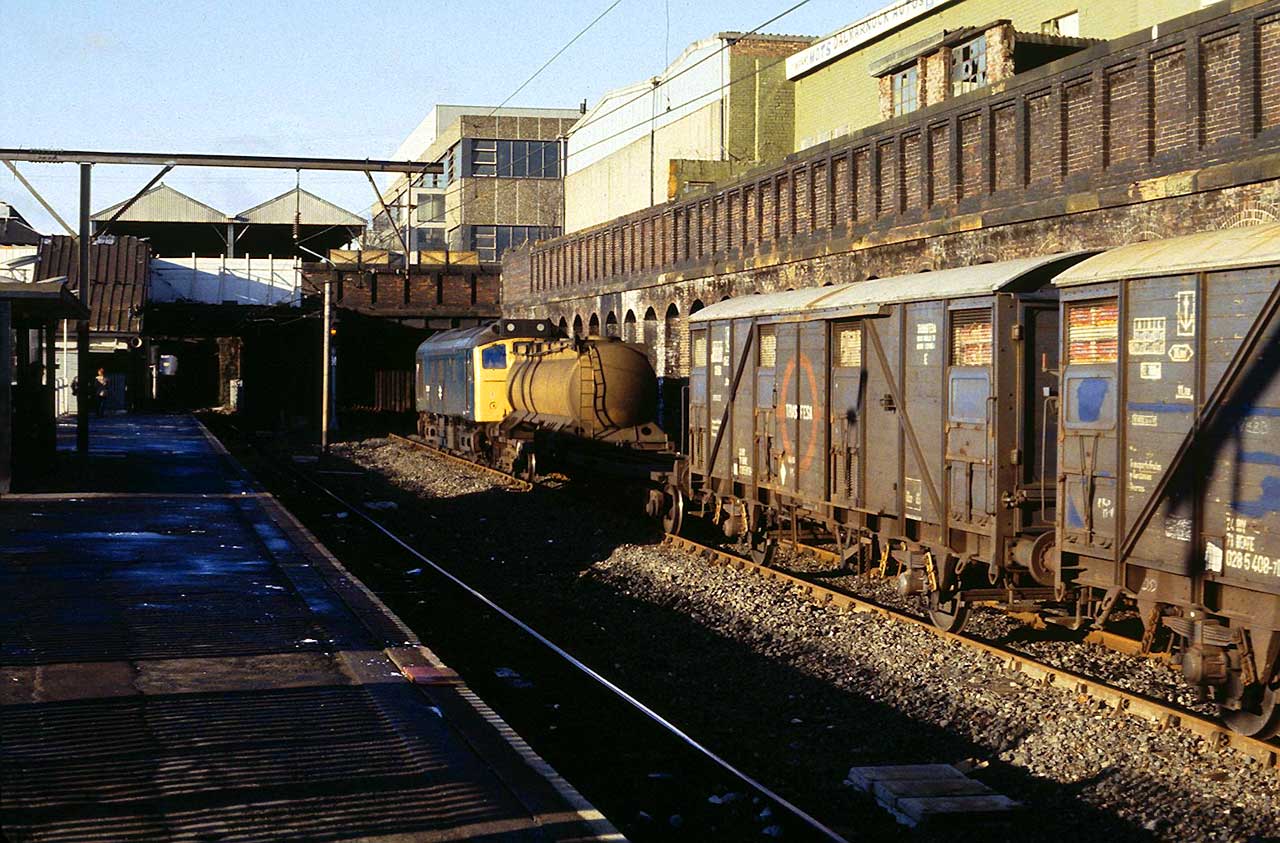
Caption for this picture, states February 82 heading into High St Goods along the Goods/slow @ Belgrove.
-
 3
3
-
-
On 27/12/2019 at 10:27, Western Star said:
Darren,
Please post photos of both sides of the wagon ends - when convenient for you.
thank you, Graham
Graham,
Apologies for the delay in replying, I never noticed your post.
Hope these are what your looking for.
Darren


-
1
-
-
Pity there is no 117 in Scotrail branded Regional Railways.
Ltd Edition anyone?
-
No problem
Darren
-
Also remember that the tail lights are different (hinge horizontal or vertical) dependant if they were Brush or Crewe built.
-
All of mine appear to be circa 46mm solebar back to back.
It doesn't look like this on the pictures but I had to hold the camera at an angle to prevent a shadow.
Hope this helps


-
1
-
-
Your in a kind of chicken and egg situation here.
My mythology for building Parkins/RJH/PMRP kits and other which have blank floors without is as follows.
1. Fit my top hat bearings into axle boxes (as deep as the casting depth will allow).
2. Fit my wheel sets dry and then measure the width of the solebar inner edges.
3. Mark a Centre line up the floor and then use this to Centre your already measured solebar width.
4. Tack your solebars in place, make sure your wheels are free running. (I use a craft knife to slide/adjust the top hats in or out)
5. Lastly, make sure your solebars are not fouling your buffer holes.
I have 3 or 4 built and painted OTA/SPA and a part built OBA that should all be roughly identical (some were built almost 20 years ago) that I will try and photograph over the festive and post up.
hope this helps
-
1
-
-
On 28/10/2019 at 19:37, russ p said:On 28/10/2019 at 19:37, russ p said:
In the 90s we had a big crowd of us who went out in sheringham on Friday and Saturday nights virtually all have now left the railway because it's not fun anymore. Even back then the drink and drug regulations were in and no one went stupid, granted on days when we weren't doing much there was some mega sessions.
I have the pictures to prove it with MM & KB, et al
-
1
-
-
Great driver, but will always be remembered for second best to Jimmy.
-
Two name and numbered version to be released by Heljan will be:-
56101 ‘Mutual Improvement’ in trainload coal and
56110 ‘Croft’ in trainload construction
-
On 27/02/2019 at 10:24, 'CHARD said:
I'd love to see a weathered one of the 5609X - 5610X LoadHaul examples, that used to shake the offices at Polmadie in the years 1998 - 2000 as they passed on loaded coal or iron ore workings. Twenty years ago but it feels like a fortnight!
Only on coal traffic and the dog food from Deanside, no Iron Ore as the Ravenscraig circuit had stopped by 92.
-
The Fife Circle 2G13 etc in 1992 was a VO Mk2 rake in Scotrail colours (reggie railways) with different branding.
The senior traction inspector at Edinburgh (LG) made noises of sourcing airbraked stock so that he could utilise 56’s and train drivers on them!
-
Think he is talking about the Mk2’s used by the push pull 27’s before the Mk3’s arrived!
-
One question for you Ben, with the caveat of I don’t know how far down the build/design you are!
Will the radiator fan vents on the body side (supports) be part of the main body shell of separate?
-
On 08/10/2019 at 14:57, 61661 said:
Just to clarify, before this becomes a(nother) scare story, the NRN aerial, cabside aircon vent and 'grid' under the bufferbeam will be separate customer fit items, so you can fit them or leave them off according to the specific loco you want to model. You'll also have the option of two styles of cab door handrail (round or flat section).
With regard to the cab roof dome, it looks different on the real thing (and also the CAD) depending on what angle you view it from, so it's possible to source images that both confirm the shape shown on the CAD and the comments about it being too flat! There's also plenty of evidence that the real things vary in shape, which makes it very difficult to create a 'definitive' shape that will please everyone and cover every loco in the chosen batch.
All the Best
Ben
Thats good to know Ben, one loco you will not be able to model will be 56085 as for some reason it was built without cab front steps!
")


Dapol Announce O gauge Turbot
in Dapol
Posted
I believe they should arrive 28th July