


cga
-
Posts
43 -
Joined
-
Last visited
Content Type
Profiles
Forums
Blogs
Gallery
Events
Exhibition Layout Details
Store
Posts posted by cga
-
-
Having read this topic and being unhappy with the DCC Concepts SS point motors, I am contemplating adoption of the MTB MP1 and would welcome advice from someone with the same operating system as I have.
I am using a Gaugemaster Prodigy Wireless DCC and use predominantly Markits EM gauge and some home-built point work, operated with 0.7 mm NS wire in PTFE tube.
What exactly would I need to purchase to set this up? Is the Digikeijs DR4018 essential?
I presume that the DCC concepts SS controller is not compatible, or if it is compatible, it will merely generate the same faults as it does with the SS point motor.
Thanks,
Mike
-
Please note that disconnecting the tender pickups does not solve this particular problem if both can touch the tender axle. Once sorted it is an excellent loco.
Mike
-
I have struggled for several years to get these SS motors working consistently. They lose their programming even on CW. Resetting does not move the actuating arm to a consistent position - easy to see if you reset a motor three times and take note of where the actuating arm stops. Apparently it depends on what throw is set. DCC acknowledge that this is the case but whether it has been rectified I don't know.
If the gremlins are really excited when you try to operate the motor it will move forward briefly and then reverse achieving absolutely nothing.
Using the controller to change the frog polarity creates a short circuit because the polarity change occurs too soon, i.e. before the pointblades have moved the full distance, and in any case they only move the full distance if the gremlins are asleep.
And as for being silent, I have to disagree most strongly.
A lot of promise but also a lot of disappointment.
Mike
-
I have just found another example illustrated by a photograph recently added to RailPhotoprints. A Midland box, Leeds Arthington Junction Box 2.
https://railphotoprints.uk/p351609472
Mike
-
I read these posts with interest because I had what appeared to be exactly the same problem on a Hornby 8F. In fact, it wasn’t the same.
The fault was clearly on the tender. The wheels were not shorting to the axles, so I completely dismantled the tender, removing the brake gear, wheelsets, body, and weight.
Refitting the wheelsets to the tender frames and placing on the track produced conspicuous flashes from the axles, and close inspection showed that the ‘floating’ portion of the pickups was able to contact the axles. Tamiya 1/4-inch masking tape wrapped around the inner part of the tender frames secured them easily and on reassembly there were no short circuits. Make sure that the tape does not rub on the wheels, and if the tape has covered the holes for the brake-gear retaining screws simply poke a fine screwdriver through to restore the hole.
Adjustment of the pickups ensured current could still be collected from the tender wheelsets, but I agree that they are a definite load-limiting brake.
-
 1
1
-
-
Thank you all for your contributions. I have collated the input regarding ex-MR elevated signal boxes and attached it to this posting for easy access by anyone interested.
Mike
-
On 23/03/2019 at 16:14, cga said:
Thank you, yes it is. It is mentioned in the Ambis Engineering document and cites the reference you have given. I missed it because they do not use the word 'elevated' in the text.
Mike
In addition to the Midland record article there is on the web another article by Edwin Course from the Railway Magazine about this box with at least one photograph available at http://www.semgonline.com/RlyMag/ForeignDepotsofSthLondon.pdf.
Thanks to Nick Holliday who in 2011 drew attention to this in a previous thread on Walworth Road Coal Drops
Mike
-
On 23/03/2019 at 16:14, cga said:
Thank you, yes it is. It is mentioned in the Ambis Engineering document and cites the reference you have given. I missed it because they do not use the word 'elevated' in the text.
Mike
Thank you all for your contributions
Regarding the positioning of the elevated boxes, that at Matlock is specifically described as being necessary to ensure adequate visibility. Inspection of the available photographs and plans in Bill Hudson's book suggest there are other adjacent locations available at ground level, although possibly the situation was different at the date of building.
Few model railways have the space to accommodate a true scale representation of any site, and usually as a consequence are crowded, and since also most are freelance rather than a specific location, a gantry-raised box is not necessarily lacking in authenticity or otherwise inappropriate.
There is (or was) another similar box at Swinton Junction where the ex-GC line from Doncaster joins the North Midland line, illustrated in Bob Pixton's North Midland Volume 3, built on an embankment and such that the gantry is only obvious when viewed from behind the box. It also appears to be one of the higher boxes with about 18 planks below the verandah, and with steps not only to track level but also apparently from ground level at the rear (possibly a canal towpath) up to the frame room access door. The track diagram is available here but I haven't found a photograph on the web. https://signalbox.org/diagrams.php?id=871
Carlton Main Sidings box is not dissimilar but the angle of the photograph does not show the gantry so clearly. With numerous boxes situated on embankments it is likely that this arrangement was quite common.
Has anyone found a photograph of the box at Armley?
The narrow base, cantilevered boxes, appear to have been more common. Another well known example was just south of Sheffield Midland.
Just for the record Hexham on the Newcastle-Carlisle line is another well known example of a box on a gantry.
-
1
-
 1
1
-
-
9 hours ago, eastglosmog said:
The fifth one is presumably Walworth Road Coal Depot, London. There are some pictures of it in Midland Record 14 (p18-32).
Thank you, yes it is. It is mentioned in the Ambis Engineering document and cites the reference you have given. I missed it because they do not use the word 'elevated' in the text.
Mike
-
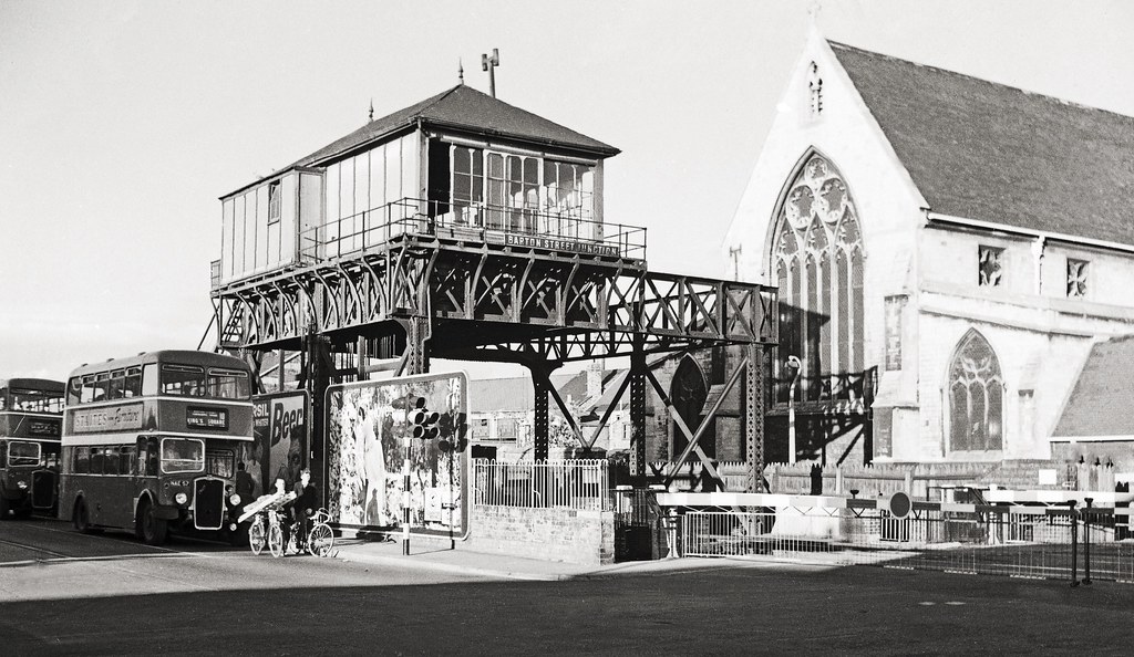
I have just found a downloadable document 'MR Signal Box Configurations' from Ambis Engineering (ambisengineering.co.uk/MRsignalboxes.pdf) that is quite helpful for MR signal box design, and which among other things states 'We currently know of five elevated boxes, all different'. Matlock is mentioned. Two others are Armley Junction, Leeds, and Barton Street Junction at Gloucester. Unfortunately the other two are not defined, but Eckington is presumably one of those. Confusingly, It also states for Matlock 'Generally fairly standard design of period 3 except it is mounted on a largely timber frame and is cantilevered about 4 feet outwards from the frame', so possibly the frame was originally wooden and altered, at least in part, at some subsequent date.
There are several photographs of the Gloucester box on Flickr.
Mike
-
1
-
-
Thank you both.
I have since found on the HMRS website a photograph of the Eckington and Renishaw box with a note that the frame is metal rather than wooden. Not surprising really as many of the Midland boxes that did not have a concrete base were susceptible to rot as described in other databases.
https://signalbox.org/index.php
Mike
-
I am aware of two ex-MR / ex-LMS signal boxes that were built in an elevated fashion such that a track ran beneath the box. One was situated at Matlock, and the other at Eckington and Renishaw . Illustrations are available on flickr and in various books such as the late Bill Hudson's 'Rails through the Peak' and 'North Midland Volume 2'. The Matlock box is clearly on a metal girder framework, that at Eckington looks as though it might be wooden. I am contemplating building a 4 mm scale model, albeit probably using a two-bay box rather than a three-bay box, and wondered if anyone can provide more information about either of these boxes or other similar ones, if indeed there were others.
Thanks,
Mike

-
Another interesting photo of the Lickey with Big Bertha and Jinty 7301 assisting, both of which carry a tail lamp over right hand buffer. Possibly not strictly as per the rule book.
Mike
-
Thank you all.
Lots of useful information collected.
Mike
-
Having read again the answers to my original question where it was pointed out that bankers might be coupled to the train in some instances I remembered reading that bankers at Glasgow Queen Street (High Level) in steam days operated coupled to the train but were fitted with equipment allowing them to detach at the top of Cowlairs Bank without stopping. The lamp arrangement in this case must have been a hybrid of the two systems unless a distinctively different third arrangement applied locally.
Can anyone clarify?
Also, did this uncoupling system operate anywhere else, and did it continue after dieselisation?
Mike
-
Thank you all. A useful collection of information.
Mike
-
Thank you both
Mike
-
Hello,
Can anyone advise what lamps would have been carried by a banking engine in the late 50s early 60s, both when assisting at the rear and when returning light engine.
Would they be the same as a station pilot?
I am thinking of Midland Region practice, but as there seems to be a lack of readily available information it would probably be of interest to cover more broadly if indeed there were significant differences.
I have searched for photographs but they rarely show the rear bufferbeam of the assisting engine. I did find one photo showing a single lamp mid buffer beam on the front of an assisting loco as it dropped off the back of the train being banked, operating on a preserved GWR system which may not relate more generally.
Thanks in anticipation.
Mike
-
Hello all
Rather late in the day relative to the original posts but this item may be of interest regarding the water tanker
https://www.swindonadvertiser.co.uk/yoursay/4517132.Letter_from_H_K_Carey/
In case the link disappears this letter stated:
'and a large long wheel base water tanker number ADB 998990' which belonged to the Stewarts Lane BDC
Mike
-
Hello Nigel
DC running has always been turned off in CV29
Loco with same decoder behaves exactly the same on a 1 meter test track used with main layout disconnected.
All other locos behave normally on the main track and the test track.
I have now tested the troublesome decoder in a Bachmann Jinty using an eighty-pin to six-pin adaptor. The problem is transferred with the decoder and is clearly an incompatibility between this decoder and this particular loco.
The inductors have been removed and any effects attributable to them can be eliminated.
I will in due course try another design of decoder. If you do try another decoder I would be interested to hear how you get on.
The recently elevated temperatures, as suggested by Phil, were not the problem, I did check during the heatwave and everything remained exactly the same with all but this one loco operating normally.
Mike
-
Hello All,
A partial solution but another mystery.
Setting the loco to 28 speed steps prevents the run-away.
However, now it is no longer possible to set a maximum speed.
Changing back to 128 speed steps restores the run-away in one direction, exactly as before, but does allow the maximum speed to be set.
Can anybody explain this?
Mike
-
Hello All,
Now the temperature has dropped back a few degrees I have been able to get up into the loft again.
The very jerky running seems to have been cured by adjusting the power leads to the motor. DC running is fine.
The runaway remains. Occasionally the loco does seem to come to a stop as it ought, but if it is prodded, or moved back a few inches, it starts crawling again suggesting that it had stopped because it had found a portion of slightly dirty track, entered a curve or a gradient such that the current reaching the motor could not cope with this increased load.
Have you noticed this Norm, or has your modification to the inductors fully solved the problem.
I think that the cause of this running away must be a high-resistance short on the PCB as suggested by Bachmann, but I cannot find a short, and am puzzled by why it should operate only in one direction.
If this is indeed a case of a faulty PCB, it raises an interesting warranty question. If a loco is bought DCC-ready in anticipation of adopting DCC at some time in the future, and that adoption and recognition of a problem does not occur until the warranty has expired, is that not rather unfair on the purchaser?
The only way to circumvent this is to require that the loco to be tested at the point of sale with a chip installed so as to be assured that all is in order.
As always comments and suggestions welcome.
Mike
-
Thank you for the suggestion, but power supply is not the problem, as this problem occurs also on the test track and on the decoder tester.
Mike


MTB MP1 point motor query
in Modelling Questions, Help and Tips
Posted
Thank you Mike, that's very helpful.
I hadn't decided how to operate the point motors, but probably by the Prodigy. I'm reluctant to completely change to DigiKeijs because of the expense, and might even revert to using the manual point levers with the wire in tube which I had originally.
Mike