


lesmond
-
Posts
82 -
Joined
-
Last visited
Content Type
Profiles
Forums
Blogs
Gallery
Events
Exhibition Layout Details
Store
Posts posted by lesmond
-
-
NGRM appears to be working again 😁.
It's Christmas in Heaven.
-
 1
1
-
 1
1
-
-
1 hour ago, Keith Addenbrooke said:
Hi Les, I’m sure you could make a few bits of cardboard into something worth seeing
Really, really not this time, but I'll report when there's some progress. Looking good at your end though.
@auldreekie - great progress there too, looking really well. I've had the same with various types of pipe.
Les
-
1
-
-
Hello fellow (temporary) refugees :)
Good to see modelling under way, I've stuck some bits of cardboard together so nothing worth taking a photo of.
Will see what today brings...
Les
-
1
-
 1
1
-
 1
1
-
-
Many thanks to John and the team for a great show.
This was our first time at York but hopefully not the last.
Les & Leanne
-
5
-
 1
1
-
-
We're all set and ready to run. This is our first time at York, so please come and say "hello" or at least point and laugh.
Stand 68 on the first floor.
Les
-
1
-
1
-
-
2 hours ago, Michael Hodgson said:
I used to use Govt surplus Lancaster bomb release switches, but they'rerather dificult to find now.
Same here, they always attract comment.
-
Very sorry to hear this.
I hope that you can quickly move on from a very stressful time 🥰.
Les
-
If you still have these, I could give them a good home.
Les
-
If you still have these I can give them a loving, smoke free home :)
-
Hi,
A bit of a random question - does anyone know the size of the machine screws used to hold H&M SM3 point motors together?
Thanks in advance
")
Les
-
Hi Stuart,
No problem - input is 16v AC.
To convert it to DC I used one of these:
https://www.ebay.co.uk/itm/264940437804?hash=item3dafae412c:g:VDgAAOSwZzxgyVLF
then used an LM7812 voltage regulator to give a steady 12v output. The rectifier above has an output of 22v DC from a 16v AC input, so a bit high :).
The 12v DC output from the LM7812 then goes in to one of these:
https://www.ebay.co.uk/itm/193312727515
which controls the voltage to the track. It has an "off" position on the pot. which is handy.
The track output goes through a DPDT switch to reverse the polarity and give forward and reverse control.
I got the bits from AliExpress - with a bit of a wait - for a good bit less than Ebay sellers want for them. This was however well pre Br%xit so import charges may well be a factor now.
Hope this helps,
Les
-
The ACME control panel for "Road Runner"


Les
-
2
-
-
1 hour ago, RAF96 said:
You could get all that in an Altoids Mints tin, which are a standard size used for packing all sorts of things, hence readily available.
I believe there's one of those about somewhere too....
-
5 hours ago, DCB said:
Er, looks good, but why? Wouldn't it be better to have a centre off control knob like a Morley and just have a potentiometer and knob in the hand held and keep the rest attached to the baseboard?
Because I could

-
1
-
-
Here's one I made today:
Slightly fiddly to assemble, but it works ok
. There's plenty of room inside the tin for the various components.
Les
-
3
-
-
The 300 mA output from the power supply would put me off it - I'd be looking for at least 1 amp.
Les
-
1
-
 1
1
-
-
I do and it works very well.
-
14 hours ago, kevinlms said:
The one thing I don't like at all, is the tight wire which appears to have caused the bent tag! It's hard to be certain, but has that pot rotated slightly?
For the sake on an inch of wire you'd think that there would be some slack. The pot does look to be a little off centre.
-
On 23/05/2020 at 16:23, RAF96 said:
One of the wires from the reversing switch to the speed control rheostat tag appears to be bent over and touching the component case. Gently bend it upright again.
Edit - there seems to be a lot of hot glue stuff in there. Doesn’t look very professional. At least it has been PAT tested at some time.
Good spot with the rheostat tag. Agreed about the hot glue as well - it doesn't really inspire confidence.
Les
-
These are a beefy controller with enough power to run a Gauge 0 or Gauge 1 controller. Don't plug it in with the lid off unless you really, really know what you are doing (this goes for anything with a mains lead).
It sounds as though the mains side of things is ok, but it wouldn't hurt to get this looked at by someone who knows what they are doing to be on the safe side, although it seems to have been PAT tested at some point in its life. This is ok and proves it to be on the day, much like a car MoT, so best to get it checked over.
For basic testing of the faults described, with it unplugged from the mains, use a multimeter to test the resistance of the potentiometer / speed control.
This should change from low to high as you turn the knob. If it doesn't, its at fault, and will need to be replaced with one of the same value (it has 10K printed on it, so 10K ohms value at full resistance).
Also check the reversing switch (multimeter again) to make sure that it is actually reversing the polarity. It should switch with a good positive click.
Either of these shouldn't be too hard to change if it comes to it, but if you aren't sure about it I can't stress enough to get it to someone who does or give it back with the same advice.
-
1
-
-
2 hours ago, BigMal said:
You have got another 51 weeks Les - assuming you will be able to bring the layout at Easter 2021.
Mal
I'd be more than happy to
. The extension is more or less done as well.
-
Don't know where we would have been placed, but here's "Road Runner" in Gnine
P8250123 by lesmond2009, on Flickr
The extension would have been finished, honest....
Les
-
3
-
-
I use XLR connectors in various guises - 5 pin for layout low voltage power (16v AC & 12v DC), four pin for controllers, and 3 pin for track power between boards (so far only one track otherwise it will need a rethink
 ).
).
They are nice and robust, latch, and by using different configurations it's impossible to connect things up incorrectly.
Agreed 100% that anything that has any potential mains usage is a no-no. All too easy to make a dangerous mistake during show setup, especially if you have help unfamiliar with your kit.
Just my 2d
") .
.
Les
-
I've got down to 4 1/2" radius with a shortened Kato 11-103 / scratchbuilt body pulling Roco 4 wheel wagons and a coach / brake / works van of unknown origin, all held up by a flowerpot
A Roco 0-6-0 won't run on it.
 Untitled by lesmond2009, on Flickr
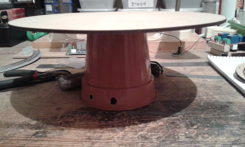 20181009_204137 by lesmond2009, on Flickr
I'd not want to go any tighter and expect to run a coupled train, unless you were to use chains or rooster bars.
Les
-
3
-


")


 ).
).
") .
.
Do you agree with this assessment of the Hammant and Morgan controllers ?
in Electrics (non-DCC)
Posted · Edited by lesmond
They have some useful control knobs and some other bits for not too much.
I notice that they are now repairing resistance mats on a exchange basis.
Les