


hendie
-
Posts
232 -
Joined
-
Last visited
Content Type
Profiles
Forums
Blogs
Gallery
Events
Exhibition Layout Details
Store
Posts posted by hendie
-
-
Thread revival!
No mouth to mouth required, just a swift kick and we’re back in business.
Just as I was finishing off this marathon build back in, what was it… October of last year? I thought to myself, that it was such a shame I did not keep any souvenirs from the 1:1 build. I know my name, along with others on the team is stamped on one of the shear plates in the vestibule end, but that’s not quite the same.
Actually, I did keep some mahogany blocks from the vestibule gangway, but my wife left those back in the UK when we emigrated. Now that the build was complete it would have been so cool to have had some of the 1:1 Pegasus to display beside this model. But that was over 20 years ago now and I am a continent away and no longer in contact with any of that team. Oh well, such is life.
Well, in what can only be described as a remarkable series of circumstance and coincidence, the end of my build was not the end of the story. Pull up a chair, throw another log on the fire, grab your Horlicks, and get settled in.
Unbeknownst to me, sometime around the middle of 2020, Pegasus incurred some water damage – any guesses where I’m going with this?
I’m not sure just how bad the water damage was, but the new owner apparently decided that was the opportunity to do a complete refurbishment of Pegasus. So in October of last year just as I was finishing up the 1:32 build, the 1:1 Pegasus was scheduled to go to the doctors for the refurb, and here’s where fate got involved.
A tremendously resourceful fellow named Andrew, who we’ll call Andrew, to protect the innocent, decided to do some research on old Car 310 – and what do you know? He came across my build thread and read through it. Now, not only did he read through my build, but after trying various ways to contact me without success, he also took the time to register with the site so he could contact me personally via PM. That was back in January of ’21.
His out of the blue PM blew me away. Simple as that. I can’t explain how excited I was when I read his message. It was fairly straightforward – he informed me that they had just completed the refit on Pegasus and he had saved some items – and would I be interested in having them? WHAT???
I couldn’t believe it. How many planets had to align for all those circumstances to coincide?
Off course I jumped at the chance. Over the last 7 or 8 months we’ve been PM’ing back and forth trying to sort things out, but finally last month everything was in place for the shipment to happen. And happen, it did.
This week I was away in Chicago on business, and on my first day away, look what arrived…

Look - it's full of goodies
Sorry, not that type of goodies.
This type of goodies
What’s in it I hear you ask. Well, there’s this for starters: A curtain. A real curtain. From the real Pegasus. Perhaps even the one old Madge wiped her fingers on after scoffing that tea and scones on her birthday
Then this, a piece of the carpet, which for some obscure reason decided to auto-rotate itself. The photo, not the carpet.
Followed by this little section of granite from the bartop - remember that bartop that I thought was going to be such a struggle? Yet turned out to be one of my favorite items in the build
Then we have a couple of brass hooks, and a pair of attendant call buttons. (You can get off your sides now, looks like we've stopped auto-rotating)
And finally, to wrap up, we have the pièce de resistance, and a part that never in a gazillion years could I have imagined getting my hands on – a section of wall panel with the birds eye maple star inlay
See - there's that Birds Eye Maple inlay I spent so long trying to figure out how to replicate.
How can I sum this up? I’m kinda lost for words. I am indebted to Andrew for going to all the trouble of tracking me down and reaching out to make contact. He didn’t know me from Adam and there was absolutely no reason for him to go to all this trouble to get these items into my hands. I will forever be indebted to him for his generosity and kindness.
The question you are all asking now is what on earth am I going to do with these now that I have them? Well, my current plan is to have a custom shadow box made up which will house these mementos and can be displayed alongside the Pegasus model.
Something along these lines
So look out for another post sometime in the future when I manage to get that done.
-
 13
13
-
 1
1
-
-
On 21/05/2021 at 18:29, Nova Scotian said:
Wishing the OP all the best, and hoping they return with another railway build soon.
Thanks NS. Unfortunately I am one of those modelers who has to have a "connection" to the subject matter, otherwise I find that my heart just isn't in it, and Pegasus was my only foray into the rail industry during my professional career. It was that connection that kept me working on it for the 6 years it took to bring to fruition.
On 22/05/2021 at 07:34, Ian Major said:I fear that this project will remain Hendie's sole excursion into the world of model railways.
Sadly, Ian, I fear you are correct. I was also involved in designing an observation car for some client whom I can no longer remember, but it never got past the concept stage so there were no drawings produced. If I ever feel the urge to model rail stock again, that could be a potential subject.
I don't want to say too much at this time, but there has been a (very surprising) further development in the story of this build. If things go according to plan, there may be a further update in the not too distant future... fingers crossed. I shall let you all know if it all pans out (or not)
-
6
-
-
19 minutes ago, Ian Major said:
Hendie, very nice. Nowt wrong with having a few gratuitous shots.
")
Did I spot the wings of a British bi-plane on your cleared workbench?
Ian.
Well spotted Ian. I'm working on a Bristol F2b from 1920, and a Hawker Audax from around 1930, both 28 Sqn aircraft
-
 1
1
-
-
On 24/10/2020 at 15:36, Ian Major said:
Boo. Hiss.
(Only joking!)
That mirror is perfect for the job though judging by Marge's eyes she is saying "HOW MUCH?"
Ian.
Thanks Ian. You can hold off on the boo hiss for a few weeks yet... read on...
A few quick jobs to finish off.
The mirror got glued in place
and a quick peek of the underside
The track end caps got glued in place
Everything got cleaned up and dusted off as best I could
The roof was finally lifted into place
quick view from the front
Then I finally pulled the display cover out of its packaging
Look mom! no train!
for the first time in 6 years, there is no Pullman car on my bench - it's a strange feeling
but not before I had painted up the plinth and added the plaque
now follows a bunch of gratuitous shots, just because I took 'em...
Officially finished.
But...
I have decided that I really do not like the rod going full length of the roof as I feel it really detracts from the roof detail when viewed in the mirror. Therefore, I am going to attempt to make the support gantries in brass which will provide much stronger supports and I should be able to support the roof with a short cantilever. Would you believe I cannot source brass H beam here in the US? I'm going to have to order a bunch of material from the UK so it's going to take a few weeks for that to arrive. That will give me a nice little break form this, and hopefully the brass gantries will not take to long. They won't be exactly the same as the 3d printed ones but will be as close as I can get them given the tools I have .
but I'm still calling it finished!
back in a few weeks...
-
9
-
 1
1
-
 6
6
-
-
On 13/10/2020 at 20:27, Enterprisingwestern said:
With regard to the ballast, presuming this will be a stationary display model, if you decide to have some, does it need to be permanently glued down, it ain't going nowhere?
Mike.
I've given up on the ballast now Mike. More arrived this week and it was the wrong scale. More importantly I really don't think there's any room and it would look forced
On 14/10/2020 at 03:26, KeithHC said:With regard to the moment. Could you fit in a counter weight at the end of the rod.
Keith
On 14/10/2020 at 04:16, jcm@gwr said:Those counter-weights could double up as the knobs to rotate the roof.
Keith, JCM, - nice idea but I'd need a really heavy counterweight with such a short moment available on the other side
On 15/10/2020 at 06:11, Ian Major said:Hendie,
That is looking fabulous with the roof posed above the body.
BTW. Have a look at this article on the BBC website. The fifth photo down should be of interest to you.
https://www.bbc.co.uk/news/uk-scotland-edinburgh-east-fife-54540298
Ian.
Thanks Ian, what a great find! Thanks for sharing - it brought back some memories
On 15/10/2020 at 07:35, Bucoops said:I read that earlier and wondered if it was THE coach!
yep Bucoops, it was indeed THE coach
The last piece of the jigsaw puzzle arrived during the week.
What it is you may well ask?
Okay then. It's a mirror. A real glass one, not one of those cheap acrylic plasticky ones.
Bloomin' expensive it was too. I searched for days trying to find something cheaper, but twas not to be. In the end, I bit the bullet and just bought it. It should show up the underside of the roof nicely with the added bonus that you can actually see some of the chassis work too.
It's just resting in place at the moment. This weekend should see it all finished.
I also bought a plaque. I'm not sure if I like the wording but couldn't think of anything else.
I also printed off a base for the plaque - which will be sprayed black in due course - if I decide to use it. I may just lay the plaque flat on the case.
Tantalizingly close to the finish line now. I can almost taste the axle grease.
-
10
-
1
-
 2
2
-
1
-
-
On 12/10/2020 at 02:31, simonmcp said:
Regarding the ballast, you could do what is done on some bridges and put in a trough , if you have a few millimetres height spare, and then the ballast would not touch the base. I realise the shape might be complex.
Thanks Simon. After much consideration I believe I am going to forego the ballast. Not 100% sure yet, but almost
On 12/10/2020 at 02:36, Ian Major said:Your concerns about PVA glue ageing and allowing any ballast to fall away is a genuine concern. Perhaps the ballast is not such a good idea - even though it was my not so good idea!
On the contrary Ian, it was a great idea. Its just in this case that I think its going to be impractical - mainly due to space limitations with everything else that's going on in the build.
A funny old day today was. It threw up a few surprises and almost had me reaching for the tranquilizers.
First item on the agenda was to mark out the base.
The white paper taped in place is my surrogate mirror. I wanted to make sure I didn't end up with the supports fixed in place then the mirror wouldn't fit did I? That would have been stoopid.
It was a case of measure everything three times, then measure it another three, then check those dimensions at the opposite end to make sure I had everything symmetrical. Then I had to drill 4 holes through the upper and lower surfaces of the acrylic base. Drilling that stuff is no fun. Not at all.
I had modeled a couple of holes in the base of the support structure as fixing points. The first attempt was using self tappers, but the deep thread on those started splitting the resin as it is so brittle. Next up was machine screws. Those managed to cut their own threads into the resin but stripped the resin easily when tightening the screws. Okay then what's next?
More machine screws but this time, I cut off their heads and epoxied the threaded rod into the support structures
That way, I could then bolt the things in from below. The old step drills came in handy again to open the holes out underneath and I managed to get a hole large enough to fit a socket through, making fixing them in place a breeze. I was careful not to tighten the nuts too much in case I puled the epoxy out of the base - just snug enough so that nothing moved, then added a lock nut for security.
Both support structures now in place, it was time to attempt hoisting the roof into place.
That was a lot easier to write than it was to accomplish since I only have two hands, and found during this exercise that I needed about 6 hands to do the job. There was lots of balancing, cursing, sweating, more cursing and the greatest fear I have ever encountered while building a model. It scared the crappola out of me to be honest. One false move, one little slip, or something giving way and I could have two years of repair work ahead of me to finish this build (again)!
The gods were smiling, well, maybe not quite smiling - I think they had more of a wry grin on their faces today.
I got everything in place and realized... Gadzooks! This is not going to work!
All these months I've been handling this roof, it felt very light. Today it felt very, very heavy, and very dangerous
I present the evidence below. Ignore the fact the roof is the wrong way up and take a look at the overall arrangement. Notice anything?
There's a bit of a bend isn't there? A hell of a bend in fact.
At this point a mild panic set in. - All this design and effort and the darned thing isn't going to work.
The moment arm on that cantilever is too long and creating the bend in the brass tube. First thought... okay, I can replace that with brass rod.
However, I'm now startling to question the support structure. The moment introduced by that cantilever is placing a lot of stress on the printed parts, particularly the angled support. The moment is also trying to tip the vertical supports in towards the center. Replacing the bras tube with rod isn't going to fix that - if anything, the rigidity of the rod is going to place yet more stress on the support structure. Okay, it's holding now, but the printed resin is very brittle and to be honest I have no idea how strong it really is or how long it could last in that state before a catastrophic failure. And that catastrophic failure could be, well, catastrophic!
It was coffee time.
I ran through a bunch of ideas with input from a few folks before hitting on an idea, that while not ideal, would eliminate the danger of the thing crumbling before my very eyes, and me lying crying on the floor.
A quick trip to the local hardware store found the supplies I needed. Of course, being in the US all the supplies were in units of barleycorns inches. I had designed the structure to take a 3 mm diameter tube/rod, and all I could get here was 1/8", and as we all know - 1/8" is not 3 mm, it's 3 point freaking 2 mm.
That 0.2 mm took a lot of work let me tell you, along with a boatload more apprehension and fear thrown in for good measure. First I had to open out the holes little by little (yes, I was too darned lazy to take the structure off the base again), before finally filing the holes so I had a nice clip fit with the 1/8" rod
and here's my (bodged) fix. One single long rod instead of two shorter rods.
Having one continuous rod eliminates 95% of the moment arm that was acting on each end structure. There is still a small, though much reduced moment acting on the angled support arms due to the slight bend in the rod, but the majority of the weight of the roof will now for the most part act down through the vertical structures where they are at their strongest
It's not ideal I know. Okay, it is far from ideal as I now have a humongous rod traveling all the way down the length of the roof, obscuring some of that detail that I spent so much time on all those years ago.
However, I'd much rather that detail be partially obscured than end up in pieces on the floor at some future point.
Now the question is did it actually work?
Have a guess...
In the interest of full disclosure I made an oopsie. But the oopsie turned out to be rather beneficial - most unlike things for me!
The oopsie was in those measurements that I made earlier. Despite measuring in triplicate triple times, and then double checking that, I had completely ignored the roof cradles in all my measurements. Doofus!
I had intended the roof to be approximately 5 mm or thereabouts clear of the car, where now, due to my utter ineptitude, the roof cradle rests ever so gently on the side-frame, holding the roof at an almost perfect viewing angle.
A clearer shot of the interference here.
I really couldn't have planned it better. Lucky or what!
With all that excitement it was time to lay down for a rest, so to finish the day off, I blackened the brass rod and gave it a shine with cherry blossom's finest
I also bought some 1/8" steel rod and may substitute the brass with that as it has less tendency to bend, though I feel pretty confident the entire structure is now safe enough.
Now that problem has been solved... those gears are whirring again, and I can now think of a way to use the same principles and have the roof un-obscured.
That would all depend on me being able to find the right brass profiles in the right lengths though and my old supply house has shut down and I don't think those brass profiles are available any longer. To be honest though - I need to finish this and put it to bed soon. I may revisit the roof supports at a future date
mirror and plaque next
-
5
-
2
-
-
On 08/10/2020 at 13:14, Ian Major said:
Hendie,
Those supports deserve to be the centre of a model in their own right. I am not sure what though - Steam Punk indeed!
Ian.
Thanks Ian - I'm very pleased with how they're turning out
On 08/10/2020 at 13:28, PaulCheffus said:Hi
The use of washing up liquid in the PVA water mix was to break the surface tension. Wetting agent as used for photography has the same effect and doesn’t turn the ballast green.
Cheers
Paul
thanks Paul
On 08/10/2020 at 13:28, jcm@gwr said:You always dilute PVA with water, but you use w/up liquid as a 'water wetter',
meths (wood alcohol) is a good replacement
I'll see what I can dig up. I'm sure I have something around that will do.
Now, on to this weeks adventures
Chicken grit on the left. Too pink and too large. The grit was intended for adult birds so I got another bag, this time intended for starter birds, and to be honest there wasn't much difference in size... and still too pink.
On the right, some other grit I found. I can't remember what exactly. The color is perfect, but the grit size is too small. I could have gotten away with it too if it wasn't for those pesky... wait. Wrong thread. The grit has some extra chemicals in it and is very damp.
I decided against using it as I am not sure how it will react with the glue etc. over the long term.
I've been reading up on how the rail modelers fix the ballast and that has me a bit worried too. It seems that a mix of PVA/Water/IPA is used. Makes sense - but typically that is used to fix the ballast to a porous surface of some description.
I have a very shiny, very hard, very non-porous acrylic base. I have a feeling that over time the PVA will shrink slightly and start peeling back at the edges. I am definitely not going to be sanding the surface of the acrylic base as there's no going back after that.
More thought required on that front, before I commit to potentially ruining the base.
On the steampunk front, the roof support structures were assembled. I used the liquid resin and some free daylight to join the upper and lower structure, and CA gel to secure the angled support arm.
The roof cradles were tidied up. Since I had never fully 3D modeled the roof, and it was hand made anyway, I had to guess at the finished dimensions of the cradle to hold it.
It turns out I wasn't too far off but they did require a certain amount of work before they would fit.
Luckily I had made them beefy enough that I could file quite a bit away and still have them strong enough to hold the roof.
The biggest issue was that I hadn't accounted for the rain guides and the end of the roof. They were 1 mm high and that 1 mm caused a lot of additional work to overcome.
Once done though, the cradles fit nicely.
I also made these end covers for the tracks. It didn't seem right just to have the ends of the rails sitting there in the open.
Once painted up they're quite unobtrusive
Now for the good part. The support structures got painted - and I used up my very last supply of now discontinued Grimy Black Flat, which has been one of my favorite paints over the last few years. I don't know what I am going to do without it.
I've given the base the first coat of "concrete"
When complete it's going to be somewhere in this location, give or take.
I'm very pleased with the supports. I don't think they look out of place and they look interesting without taking over the view. I will admit to a certain degree of panic towards the end when I knew I had to create a support structure but went through 3 or 4 designs - none of which I was happy with. Stumbling across this idea was fortuitous indeed.
Aside from the ballast question, the biggest issue I face now is: The support structure is black - should the cradle also be black? It's going to be pretty stark against the white roof. Or should I paint the cradle white to blend in with the roof? But I'm not sure a white cradle and a black support would look any good. Black it may have to be.
-
7
-
3
-
-
On 06/10/2020 at 12:23, ikcdab said:
This really is the most excellent model. I have followed it for several years with a huge amount of admiration.
I think that with such a first-rate model, the track should match it with prototypical chairs and keys etc.
For ballast, I guess O gauge granite chips would work fine.
thanks for the kind words ikcdab.
On 06/10/2020 at 13:00, Ian Major said:Hendie,
I agree with Ian.
I notice on the left of your photo you have some spare sleepers. I think I would use them to experiment. If it looked fine and to your taste then go with it. As you say you don't want to glue ballast on to your base only to find that you didn't like it.
Everyone I know who do ballasting use diluted PVA on to the ballast after it is brushed between the sleepers. Something to watch here is that some ballast chippings go green if they react with the PVA.
The watchword is "experiment" on a test piece - something you are very good at doing.
Ian.
I have some poultry grit on order so we'll see how my experimentation works out
On 06/10/2020 at 14:22, jcm@gwr said:I think the general consensus was, that it was the w/up liquid (used to help the PVA flow)
that was the cause of the 'green-ness', it tended not to happen if meths was used instead.
So diluted PVA (with water) would work?
I have been printing the last pieces of structure over the last few days but encountered some issues. These are the end caps for the tracks...
and as you can see clearly - print failures. Temperatures have dropped drastically over the last couple of weeks and the basement temperature is at the bottom end of the recommended printing range, but I'm not certain that was the root cause, especially as I have printed successfully at lower temperatures before.
The prints failed because the supports separated from the structure. I believe that was because the walls in those areas are relatively thick.
I'm using a new version of Chitubox and went with their default auto support feature for these prints.
In the shot below, another print failure on the left - so went back and added more supports to the bottom end, and this time it printed successfully.
These are the additional parts need for the structure. The steampunk arches printed successfully as did the girder sections, but the two arc thingies were another print failure. There should have been a hook feature on each end of the arc. However, the prints have failed in such a manner that I may be able to add the hook from styrene sheet. If that doesn't work, I know what the problem was and can simply reprint them
I still get amazed by the level of detail every time I print something. The rivets and joint plates on these are only 0.3 mm thick.
but what will it look like assembled? Well, your wait is over - it's going to look like this
Parts are just resting against each other here and I used a scrap piece of brass rod just to see how it's going to look.
The arc support is going to be fitted onto the end of a rod, and that is what the roof will be sitting on, which will allow me to rotate the roof to the best vantage point.
it kind of sucks as I have a pest control guy in today as I got a hornet infestation in the basement in the last week so I have to stay out of the area while his poisons do their work - and I took a days vacation today too! Arghhhh.
I had lots of things planned, but they're going to be delayed until I can get into the basement again without being poisoned.
-
5
-
1
-
-
1 hour ago, Ian Major said:
Is it worth ballasting the track?
Thanks Ian. I knew the ballast question was going to crop up.
I'm undecided at the moment - for the following reasons:
1: There will be a mirror mounted directly on the base on the same side as the roof. That mirror is going to butt up very close to the sleepers and will match the full length of the car, so there wouldn't be much room for spreading ballast. The ballast would have to stop almost at the same line as the edge of the sleepers.
2: There will be a engraved plate on the front side at the center ( 2" x 4" or roughly 50 mm x 100 mm). Again, that will butt up almost to the edge of the sleepers, maybe a 10 mm gap or so.
3: Once I start, there's no going back as I'll never get the base back to the glossy shine it now has.
I'm certainly considering it though. Any tips on laying ballast? and what size/grade I should go for?
-
On 06/09/2020 at 02:02, Enterprisingwestern said:
Very nice, but where are the pictures of the model helicopter?
 On 06/09/2020 at 18:31, MikeOxon said:
I only found this thread in time to catch the result of 6 years work!
welcome aboard Mike. Glad you found the thread.
3D printing is a marvelous innovation for us modelers, especially as it has now become affordable to most folks. I find it particularly helpful where there are multiples of an object to be made. I really enjoy the scratch building aspect, but when I have to make multiples. I find I always lose interest after about two copies. It is also extremely helpful for some object that just couldn't be made by hand - the luggage racks for instance (at least not by my hands)
On 06/09/2020 at 05:25, Ian Major said:BTW. Being extremely nosy, I am always interested in what goes on in the background of photos. For example, in your case I am intrigued by Marg Simpson, Yoda (apparently stopping a reel of solder floating away), a galloping wolf and a diver's helmet.
No problems Ian. Marg I believe was in a McDonalds happy meal that my daughter got many years ago. No idea how it ended up in my basement.
The baby Yoda? My daughter wanted one so I printed one - then she bought a larger one so now Yoda is Keeper of the Solder.
The galloping wolf was a present from my daughter after her first visit to the Safari park back in Scotland.
The divers helmet - we were visiting one of the local beaches a few years ago and one of the shops had a full sized divers helmet on display. I commented that I had always wanted one, and my mother in law found the divers helmet (actually a pencil sharpener)
Soon to join the horde is Jack Skellington (one of my all time favorite movies) - my daughter found one in a shop just last week and bought it for me.
Look!
 The display case arrived
I'm avoiding unwrapping it until it's absolutely necessary due to the amount of dust in my incredibly untidy basement.
First job on the agenda was to sort those tracks. I had read a few threads around t'interweb about the Brass Black and it was suggested to soak in vinegar prior to applying the blackening agent. So, out came the wire wool again and the tracks were given a good thrashing to remove all the blackening. Then I had to find a container that I could fit the tracks into - remember these are over two foot long. After searching fruitlessly (why do we search fruitlessly?) for a tray long enough, I came across a length of Schedule 40 PVC pipe that I had lying about.
I cut the pipe to length, and glued a bottle cap onto one end using Gloop, left it overnight to cure, then filled it up with vinegar.
Only to make the discovery that Gloop doesn't like vinegar and about 3/4 of a pint of the smelly stuff ended up on the floor. (Good job it's a cement floor!). Rather than spend half an hour to go to the hardware store and spend about 50 cents on a proper end cap for the pipe, I scoured the basement over two days before coming across a silicone mold that I'd made years ago using a measuring cup as a holder. That meant I had a nice little Silicone stopper shaped thin.
That was too big to fit into the pipe!
I made it fit eventually and this time the vinegar stayed where it was supposed to stay.
Two days later and out came the brass tracks. This time I made sure I only handled them while wearing gloves. They were rinsed and dried in preparation for the black stuff
This is after the second application (I think). I took shots after each application but the camera seems to have eaten one and I'm not sure which.
The black stuff was applied liberally by brush, allowed to soak for a while then the excess was rinsed off with water and they were left to dry.
I still had an uneven finish, with almost bare brass showing through in places. I'm not sure what's going on there... something to do with how the tracks were formed perhaps? Density? Hardness?
Anyway, I had them almost there - just need some finishing touches.
After some cleanup, the tracks were fitted into the sleeper carriers. I know the sleepers aren't the best, but they're polypropylene so won't accept paint so I'm going to leave them as is (but remove the dust!). The star of the show after all, is Pegasus. I'm not after a diorama (especially as I'm not very good at them).
I was a bit concerned though at the longevity of the finish. I know the black parts will be adequately protected, but what about those bits with some brass showing through... are they going to corrode over time?
Then I had an idea. Bull!
No, not that kind of bull. The polishing bull, like wot we did wiv our boots back in the day. Out cam Cherry Blossom's finest dark brown polish and the result can be seen here.
Front rail is untouched and the rail at the rear has been polished and buffed. It's difficult to capture in camera, but the rails now have a lovely bronzed look to them, and look good, without being tacky or kitsch (imo anyway).
Now it was time to get down to business - setting things out for their final resting place.
The tracks were held in place by three self tappers down into the base. The material is a very hard acrylic and I was very conscious of making sure the hole was large enough so that the base would not crack, but small enough so that the self tappers would grip.
Then I cracked it anyway!

I was using the pillar drill to make sure the holes were truly vertical, and the drill "caught" and slammed the base up into the chuck. I was lucky. The base did crack, but only about 3 or 4 mm, and all under one of the sleepers.
Needless to say the remainder of the holes were drilled by hand.
The tracks were taken care of by the self tappers, but I still had the car itself to fix to the base. That was achieved by drilling completely through the base, then opening up the hole on the bottom side with a step drill (incredibly useful tools) until the hole was large enough to get the head of the screw through. If you can remember back a long time ago, I used coupler nuts on the underside to help secure the bogies. My plan worked!
The screw comes up from the underside of the base, and screws right into the coupler nut at the center of the bogie.
Okay, it's noticeable of you know where to look , but it's unobtrusive enough for me.
Look, the car finally affixed to the base. (though it may yet come off again for some more cleanup and dust removal)
and just to prove the fixing method worked....
I've actually had it perched at about 45 degrees and there was no movement. I even gave it a little shake, so I am confident it's going to be safe for the long term.
That just leaves the roof. That darned roof. How as I going to hold that in place for the display?
I didn't want anything to obscure the full view of the car from a side on view, so that meant that the holding method had to be cantilevered.
Well, I tried a whole bunch of designs and wasn't happy with any of them. They all looked crap. Then I hit on the idea of looking at photo's of railroads and rail yards, and came across the idea of a signal bridge. After messing around in Solidworks I came up with this idea...
I tried to make it look like something that wouldn't look out of place in a rail yard or beside some tracks somewhere. Overall it's about 75 mm wide at the base, about 180 mm tall and about 6.5 mm deep at the girder section (a bit thicker at the footing)
I'll print this in two sections - unless someone tells me I'm absolutely crazy and this looks dreadful - which is not out of the realms of possibility!
I can then hang the roof from this, cantilever style like so
The cantilever moment will be shorter in the final product. The roof shown above is not complete.
I'll also have a bracket which will allow me to rotate the roof along the longitudinal axis to show it to best advantage (I forgot to take a screenshot, sorry)
Almost there, almost there.
-
5
-
4
-
-
On 29/08/2020 at 18:37, Ian Major said:
From the first photo I assumed it was quite a large model. Then I saw your hand in some of the later photos.
I've just got big hands Ian!

I got some better shots of the roof. Rotating vent in focus this time
All vents and greeblies fitted, and shinied up
Definitely shiny. I am very impressed with Mr Color crystal clear and their leveling thinners.
I still need to address the whole display case thing though. Not only the case but the tracks themselves.
They've been lying in my basement now for the last several years, and the brass has started to get a bit grungy
That's nothing that a good attack with some wire wool won't sort out, but it did alert me to the possibility that this may happen over time in the display case. As nice as bright clean brass is, I don't think I want the polished brass look on the tracks themselves. For one, real tracks are not brass, and two, shiny brass in the wrong setting can look a bit tacky.
A quick search on Amazon brought some brass blacking solution. Tracks were cut to length, and attached with wire wool. Blackening agent applied
and it didn't go according to plan. Some parts of the track looked really good, but in others the blackening didn't appear to work. I wire wooled the tracks again, then followed that up with a dremel clone wire wheel, then degreased the tracks and applied the blackening agent again. .
Some of the black wipes off with just a light wipe of paper towel, and other bits need a good scrub with wire wool to get back to brass.
I'm wondering if the black will give a good key for paint, and I may just spray the tracks, sleepers and all with a not quite black, black. Need to ponder that one.
I did make one discovery though - my original plan of mounting the roof in front of, and below the car was not going to work. Now that I had the car and the roof I made a mock up - forgetting to take any photos and realized that my plan was just not viable.
That lead to a mild state of panic before realizing that there was indeed a relatively simple option. I could simply display the roof as if it were hinged open, like so
A quick check with some plastic mirror reveals that this option will work.
I still need to figure out the actual mechanics of how to mount the roof. It's too late in the game to have a hard mounting point on the car itself - at least not without damaging something. However, the roof has to be close to the car in order for it not to look strange.
I'm mulling over support options for the roof but haven't yet settled on anything.
At least I can now get the final dimensions of the display case.
-
6
-
2
-
-
On 22/08/2020 at 18:49, Ian Major said:
I like looking at other model forums because the guys from other branches of modelling have skills from which we in railway modelling can learn and vica versa .
I completely agree Ian. BTW, I checked out some of your work and was blown away by the craftsmanship and skills you show. That ships stove is a model in it's own right, I can hardly believe some of the detail you've captured there. Fan-bloomin-tastic!
On 24/08/2020 at 09:46, Nova Scotian said:Your modelling plans are incompatible with my rmweb enjoyment. Please reconsider
") On 23/08/2020 at 07:57, laurenceb said:
On 23/08/2020 at 07:57, laurenceb said:We dont want to lose you!
https://www.rmweb.co.uk/community/index.php?/topic/42805-non-railway-modelling/
Thanks @Nova Scotian & @laurenceb - you guys are too kind.
A busy week prevented me from descending into the basement - that plus a whole lot of "cannae be bothered" this week for some reason. But the weekend comes around as it does most weeks, and on Friday night I couldn't be bothered either.
It got worse as I only managed to get half the grass cut yesterday before getting hit with a huge thunderstorm - which means that the grass cutting now hangs over me like a large dark cloud until I get it done - but it chucked it down again today so I sauntered off doon the basement.
First order of the day was to splat some brown/umber on the ends - a bit of a cheat, but this way the white will still follow the lines of the actual roof and the brown will hopefully fade into the background. I doubt it will ever be looked at from this angle anyways.
First pass of white paint.
Then on the second pass as I was turning the roof around my grip slipped and the roof fell against my shirt. Oh flip I muttered.
The main problem with the roof is it's sheer size. - Just over 600 mm long (2 foot'ish) and just over 80 mm (3 inch'ish) wide and since I am painting the entire top surface the only way I can hold it is by resting it upon my hand - and remember, I'm waving around a live airbrush in my other hand. So it's two arms waving around one balancing and turning, while the other tries to aim at the roof and not spill paint all over myself. I'm not good at this multi-tasking malarkey.
It could have been a lot worse - it wouldn't have been the first time I had dropped a model onto the floor while painting - though thankfully I haven't done that for a while now.
Rather than panic and try to rescue anything at this point, I sat it down, walked away and left it for a while. Once the paint hardened sufficiently I gave it a quick micromesh and smoothed it all out.
That allowed me to start applying the next coat.. until I ran out of white paint again!!!
Fortune was smiling on me this time though as I got enough coverage and could call it a day.
There's still a few small gaps around the rain guides but I've applied some diluted PVA to close those up.
Now it was time for those last pieces of this six year jigsaw puzzle. The brass channel got a lick of white paint (some dregs in the bottom of the jar)
Then super-glued in position - after careful and repeated measuring to make sure they were centered. Then just to close up any gaps that may be showing from the side, I glued small strips onto the roof adjacent to the verticals.
I then spent about 15 minutes trying to find the tread-plates I had shaped a few weeks ago, but they were nowhere to be found - must be in that safe place again. Just as well really because when I pulled out the styrene sheet I cut them from I realized it was way over scale. I had a backup plan though - I had purchased some photo-etch tread-plate a few years ago for something or other - it may even have been for this job... who knows? It turned out to be perfect
Some more dregs from the paint jar were summonsed and there was just enough to cover the new additions to the roof.
A half hour to dry then I hit it with the gloss coat. Mr Color Crystal Clear is becoming a favorite - easy to apply and gives a nice shiny hard coat when dry. It goes on a lot more evenly than other clear coats I've tried.
I even had an Oh Crap moment when near the end, my airbrush coughed and splattered a few big drops just as I was finishing off. Lo and behold - I was also using Mr Color Leveling Thinners - and the splatters leveled out before it dried. Amazing. I think I'll be sticking with that combo in future.
I'll run some micromesh along that brown/white border later once the clear coat hardens to clean up that rough look.
It's hard to capture the gloss finish on a white surface, but it's there believe me.
The completed roof - oops - still got the rotating vents to add
That will be tomorrows job.
So, how does it feel after 6 years on and off of slogging on this build? Well, to be honest it's all a bit of an anti climax and left me feeling a bit empty. There was no huge "reveal" at the end, nor was there a "this bit goes here" and wow, all of a sudden, it's a train. It was 8 little pieces that could have been assembled anytime during the last few weeks. Maybe it will sink in a bit more over the next few days or weeks.
As you are all aware I still have to order the display case. I have deliberately delayed ordering it until this point. Now that the roof is finished I can mock up how it will look in the case and check just how much room I need underneath it in order to be able to see everything with a mirror.
That means there's a little bit more to come on this build, but nothing as exciting as the last half decade.
You asked for a link to some of my other work.
Here's a link to a build I did a couple of years ago. The finished build can be found at: https://www.britmodeller.com/forums/index.php?/topic/234994581-28-sqn-wessex-xt678-hotel-hc2-raf-sek-kong-19823/
That link also contains a link to the build log
Or my My very first build after returning to modeling after a 40+ year break. Starting with this...
and finishing up with one of these...
I go by the same moniker over on that forum so you should be able to stumble across some of my work easily enough
keep yer masks on!
-
7
-
4
-
-
On 17/08/2020 at 18:37, Ian Major said:
A suggestion - rather than spending money on expediting delivery of, say, paint, how about using the wait time to prepare for the next project
Thanks Ian. I've already started my next project but unfortunately, it's not train related. I'm going back to aircraft modeling again. Won't you guys be glad to see the back of me?
This week was a bit busy so I did not get as much time on Pegasus as I had hoped, however, I managed to lock myself away today and get some work accomplished - it's getting Sssoooooooo close I can taste it.
I wanted to get the interior done before I started adding greeblies to the outside as it was a certainty that if greeblies were on the outside, I was going to knock them off as I worked on the ceiling panels. First order of the day was to fit the chrome down-lights in the bar - easy job for once
They were followed by three more down-lights in the ceiling panel, in turn followed by two brass vents and the PA speaker
By this point things are moving fairly quickly as there's no real "work" to be done - just measuring a location and sticking something on there.
More vents, another PA speaker and the six double lamps. Can't get more straightforward than that can we?
Lastly, the dinette ceiling got a PA speaker and it's own brass vent
Overall view of the internal gubbinses.
That's all fine and well, but its all much of a muchness - too much white and there's nothing that really draws the eye (is that a bad thing?).
I had anticipated this and had a sort of plan. I wasn't sure it was going to work or not but I knew I needed to do something to break up all that white area. I opted for adding the structure that would have been attached to these panels had the roof actually been fitted. For example, red oxide strips where the side frame would have been, and wooden strips where the partitions would have been located.
Now things got a bit more complicated and I actually had to measure and cut with reasonable accuracy to make this thing work and not look plain sloppy. For the "side-frame" I'm using the very last of my 1/32" ply - the very last! I had to scrabble around to find enough to do the job as I really didn't want to have to place another order of this stuff just to finish off the last few inches of roof. Once I had found all I could, I cut it into 3 mm strips and painted red oxide.
That seems to break things up nicely.
Kitchen & Corridor end finished off
Then Bathroom, corridor and dinette area finished.
I then realized that I also needed to add framework for the entrance doors and vestibule area... 20 minutes later it's done
Close up shot for no other reason that I took the photo
Then the other end
and the interior of the roof is FINISHED at long last. Only 4 years behind schedule but its done.
Now onto the very very very last area of work (I think)
The roof exterior.
First job on the exterior was to cap the ends so that you couldn't see in behind the paneling.
To be honest I'm not that enthralled by how this turned out and I know it's not 100% accurate, but I really don't see any other way of doing it. I think once it's all painted it won't look as cludgy - I guess I'll find out later
(oops spoiler alert - you can see the rest of the roof here)
again, this went very quickly as it was just sticking bits into the holes. Starting at the kitchen end...
center portion
Lastly, the dinette end
The only thing left to go onto the roof now are the tread-plates at either end. I didn't fit them at this point because it would have been impossible to paint inside the supports so they will get added once the roof has received a good coat of white paint.
All things going well, I may even get to throw some white paint on it tomorrow
-
6
-
10
-
-
that's fantastic. The wealth of detail belies the true scale of Fun Town - I had imagined it being much larger. Somehow the small footprint makes it all the more interesting and captivating
-
 1
1
-
-
This week has not been the best of weeks. After running out of white paint the other week I scouted t'internet looking for Mr Color Flat white at a reasonable price ('cos I'm stingy), with reasonable postage ('cos I'm even stingier when it comes to P&P) and that could deliver in a reasonable time frame. My usual source always seems to have the best prices but they always take about 2 weeks to deliver and I didn't want to wait that long. Anyhow, I found a place that had everything in stock and chose expedited shipping for an additional couple of bucks.. and sat back and waited... and waited. A week goes by and nothing so I gave them a call only to find out that the post had gone sideways and somehow my order had gone off to some international depot instead of priority ground mail. Long story short, I complained and got my postage costs refunded but still have to wait on them sorting things out. Ding ding - Amazon Prime time. Extortionate cost for a single pot of paint but a promised delivery of Tuesday coming.
So, until then I had to find any little jobs that needed doing to tide me over until the paint shop is up and running again. Sadly, I found more than I had bargained for - why do you I keep finding more and more little finicky tasks to complete ?
This week in pictures.
Rain guides. Not only do we have the rain strip/gutter all along the side of the roof but at each end we also have 2 x rain guides mounted further up on the roof. These were made from equal angle and contoured to follow the roof curves.
Luckily I found some 1.25 mm angle in my stock - not much, but just enough to do the job. I say lucky because when I went to search online I found that K&S appear to have dropped most of their line and no longer make brass angle. To be honest I think this angle is slightly undersized but the only other brass angle I had which suited was too short to do all four guides. Styrene angle wasn't even in the picture for this job.
Because of the compound curvature at the roof end, I annealed the brass prior to bending and it was fairly straightforward to follow the initial bend.
But hey! nothing is ever easy is it? As the rain guide bends over the roof end, it also curves out towards the side. There's no way I was going to trust superglue to hold this in place so had no option but to pin the angle as well as gluing it in place.
Drilling wasn't such an easy task either - The smallest rod I had was 0.3 mm and if I drilled that size hole in the angle right off the bat, it deformed the edges. I had to drill with a 0.25 mm bit first which allowed me to get the drill right into the corner of the angle, then open it out to 0.35 mm - there was no way I could get the 0.3 mm rod through a 0.3 mm hole - so had to go larger.
Getting the 0.3 mm pins to work was another palaver. - I had to tin one end of the pin, then pressing on the tinned end with the soldering iron, the pin heated up to the point where the solder melted and the pin pushed down into the hole - almost, but not quite flush with the surface of the angle, and solder flowed along the inside of the angle making it more of a triangle than an equal angle. Much cursing and phenargling about with a 3 square file let me clean out the inside of the angle and get it looking reasonable.
The pins didn't need to be long - just long enough to secure the rain guide so it wouldn't come loose later. Here's one about to be glued before it's pushed home
followed by (a different) one glued and fixed in position
Me being a belt and braces sort of bloke decided that I should also drill the end as it swept over the roof - this was about the only way I could guarantee that all 4 ends had the same curve/sweep as it meandered over the edge and out towards the side frame.
More drills gave up their lives for this cause than any other job I've ever done before. I think I had a sense of frustration creeping in which didn't help. These 4 rain guides took the best part of two days work to get done and I must have broken at least 15 or 16 drill bits in the process. However, job done now (for the most part) and I'm glad that part is over.
I really wanted to get the interior/ceiling finished before starting on the exterior of the roof, but things being what they are and wanting to get this finished before the next ice age I opted to move forward with the exterior, knowing that this is going to take very careful handling from now on in order not to wreak havoc and mayhem with the parts I'm just about to attempt.
I glued in the mounting plates for the rotating vents and made a start on the wind deflectors
This time around, instead of just compound curves we have a compound curve and compound angles. It just gets better 'n' better dunnit? Praise be to the modeling gods.
I started with some 3 mm wide strip and fettled that into shape with numerous dry fitting to make sure I got the angles right. Now, when I say "right", I really mean doesn't look like crap! As these 1:1 parts were being reused from the original car, I didn't see the need to make detailed drawings of them and instead, just took overall dimensions - omitting to note any of the angles. That meant lots of looking at reference pics and trying to obtain something that looked vaguely similar.
Once I had the main parts glued in place I added the three support brackets on the inside of each deflector.
Then double check the rotating vent can still rotate - or there would be some classic Anglo Saxon filling the basement.
While doing the research on those rotating vents I spotted something I had missed up until now - The 4 torpedo vents at the roof ends do not sit flush on the roof as I had previously assumed. - They are mounted on small circular plinths.
What is a bit weird is that those plinths change the angle that the torpedo vents sit at relative to the roof - but not horizontal. (as can be seen in this photo)
Back to the lathe then, and a little while later I had a handful of plinthy things
which will sit on the roof tween skin and torpedo vent
Torpedoes have now been glued onto those plinths and set aside to cure.
As a last task for today I hurled some primer on the new additions to see how effective they were and how much tidying up is going to have to be done. I like the primer stage - it always goes on easy and really makes the detail pop
Yup, I'm quite pleased with how those turned out and everything appears to line up as it should.
This photo shows what I mean about the compound angles
Lastly, how did those rain guides turn out?
Not too bad but will need a little bit of filling at the join to close up any gaps, but overall, acceptable
I still need to decide what to do with those roof ends - which is something I should have thought of before fitting the rain guides. Hey ho.
stay safe folks and if lady luck is smiling on me I may get my mitts on some white paint before the week is out.
-
10
-
6
-
1
-
-
4 hours ago, Ian Major said:
I decided to find out what it really was - I am now going to get some for my slightly gritty primer. So, thanks for the pointer.
")
you're welcome Ian.
Just to make sure - these are the micromesh sanding pads that I usually purchase though I also buy micromesh in sheet form
Those links are to US products but I know you can get them easily in the UK. Used wet, you can get a remarkably smooth finish. I used the pads on the side frames when I painted them, it really brought up a shine.
I'm glad you like my mistakes
- I always find it helpful when reading about how others overcome issues or problems and I feel it's always worth pointing out in case others can avoid the same issues - or if they do end up with the same problem, there's at least one method to try and overcome the issue.
-
3
-
1
-
-
Thanks Nova Scotian - that made me smile.
And on to this weeks shenaniganneral exploits.
in a rare moment of forward planning and intensive aforethought, when I made the bar, I had the sense to copy the outline of the bar front and put it in a safe place. In even stranger circumstances, I managed to find it when I actually needed it.
Why? Of course, there's no bar on the ceiling but there is a sort of canopy thingy fitted to the ceiling (the correct term escapes me at the moment) which mimics the shape of the bar, albeit set back slightly. For want of a better term, let's call it a pelmet for the moment.
This was a job I was not looking forward to and even considered leaving it out of the build, but my conscience wouldn't let me. The reason was because it was such a bloomin' awkward shape. The bottom edge was parallel to the bar top, the front edge was set back slightly, and with the pelmet being curved, and being fitted to a curved ceiling, it meant that the height at the front and rear of the pelmet was not the same - and that only gets worse as it rounds the corners - and the end disappears into the ceiling. Not to mention that my ceiling panels are not the best.
Anyway, step one... fit a 3.5 mm strip along the back edge.
Some careful shaping and filing later, it looks as though we have a winner on the back edge. That was the easy part.
Much phenargling ensued, mainly getting the main surface level so I could measure the height to the ceiling panel at the highest point. I determined that to be around 5.5 mm, so another strip was glued around the front edge, along with a few little strengtheners to keep that front edge perpendicular to the main surface. At this point I had resigned myself to using this version purely as a template to get what I needed for a subsequent "real" version.
Some more refining on the rear edge, and multiple file a bit, and test fit loops for the front edge.
and I completely surprised myself by managing to get a pretty reasonable fit after about twenty minutes of shaping/fitting. So much for this being a template then.
with the pelmet/canopy/thingy in a decent state, it was back to the lathe and I turned a handful of aluminum down lighters. Now I wish I hadn't used a scrap piece of styrene for the pelmet as there was a big score along the surface. Oh well, that can be fixed with relative ease.
Next operation was to fit the ceiling panel cover strips - a bunch of 1.25 mm strips glued into place. That big mucky spot is where a hoge great glob of Tamiya thin dropped on to the ceiling when I wasn't paying attention. It was quickly wiped away before it caused any permanent damage though not before it managed to marr the surface. Another one of those 'doh! moments.
At this stage I'm not sure whether the ceiling is salvageable or not but tehh thought of having to rip it out and start again was a bit soul destroying. I decided to chance it and when the glue had dried I micromeshed the panel and wait to see what it looked like with primer on.
The unnameable thing thing got fitted - surprisingly easy too. I really thought this was going to take me days and days of work to get right, but it really went together remarkably fast.
End panels were fixed in place using 5 minute epoxy
followed by a bucket-load of primer getting thrown at it. Thankfully the glue mishap is completely hidden now.
I'm quite pleased with how this all fits together. There is a small gap here and there, but overall it's a decent job. (note to self - micromesh the front of the pelmet to get rid of the grainy primer finish.)
As is always the case, immediately after I primed the ceiling I remembered that there were vents fitted on the ceiling partitions. I needed a total of 5 vent covers, but only had, or could only find two left over from my printed versions.
In a stroke of luck, I remembered that several years ago I had photo etched some of these, back in the days before home 3D printing became affordable - and what do you know.... 3 of them! Talk about luck.
Fitted!
With all that done it was ready for paint. White of course.
Would you believe it! Now is NOT the time to run out of white paint. Buggrit
I was one coat short of finishing the paint job when I ran out. I got some more on order though it will be a few days before it's here. What a pain.
So with the paint shop on furlough due to lack of materials I had no option but to faff around with all the little bits that were left, such as painting the double lamps for the dining area
Clear coating the brass vents so they don't tarnish over time. I also added the small handle from 0.3 mm rod and the small round "handle" on the end was formed by crushing the end of the rod in the vise.
Another pita job was forming the up stand for the treadplates on the roof ends. I started this job on at least 3 occasions, each time with a different approach before finally settling on using brass C channel (yes, that murky looking thing is actually brass C channel) to form the upstand.
I found some brass treadplate in my stash so I'll replace that plastic treadplate when the time comes.
Almost there, almost there....
-
7
-
11
-
-
Love it. I absolutely love it. In some respects it reminds me of a Tim Burton set.
Would it be possible to take a few overall shots of fun town and take us on a walk through the metropolis? I can't be the only one who's drooling in anticipation of seeing more
-
4
-
-
- Popular Post
- Popular Post
Now. What have I been up to over the last few days and nights. Well, sanding mostly, and a little bit of painting but really, just more sanding, with some extra sanding thrown in just for fun. I think I'm nearly halfway there now - just a bit more sanding to do.
I found a tin of white primer under my bench so thought I'd give the roof a squirt as I was getting fed up with fifty sprays of grey. It's starting to look like the Pullman roof but there's still a ways to go yet.
Like more sanding! By this time I had run out of white primer and it was back to the grey yet again.
However there is a slight piece of forward progress in this shot - see the white strip along the side edge? I glued lengths of .25 mm styrene along the side, then just for kicks, sanded most of it away.
But it does make a decent rain strip though. It is called a rain strip isn't it? If not, it should be. No ambiguity calling it a rain strip is there? and a lot more concise than the strip at the roof that stops the rain falling down the sides strip
With the rain strip in place I could start on the internal gubbinses for the roof. First up were the ceiling panels in the vestibule ends. I thought I was done with all that staining and varnishing when I finished the interior paneling, but t'was not to be.
I went to all the trouble of shaping those panels to fit the contour and match up with inside edge of the styrene strip before I remembered that the doors were inset and it would actually be a straight line from front to back so I'll need to mask those off and paint part of them white later. Oh well, why do things the easy way eh?
In the vestibule ends there is a raised center portion. It's probably not as high a step as I have it here, but I thought it would make the end of the roof look a bit weird so I'm claiming artistic licence here. Throw accuracy to the wind I say
Kitchen end ceiling panel. The PE grill I repurposed from some leftover photo etch on my Wessex build. The ceiling light is a piece of aluminum rod I turned and drilled on the lathe and the "glass" shade is a piece of clear styrene runner cut, slightly domed and polished back. Not too polished mind - otherwise you might see all the crap hiding in the ceiling void
At the opposite end, we have a longer section of corridor leading from the vestibule, past the dinette, and leading to the dining area.
This may not look pretty but it's robust and that's all that matters when this won't be seen. - When this lot goes together it's never coming apart again (I hope). Belt and braces approach.
For the ceiling panels I am using 0.25 mm sheet styrene. There's a lot of trimming and fine adjustments before the panel can get glued into position. Especially when you misread the rule and cut the ceiling panel to the wrong length - I managed yet again to misread the same measurement at least 4 times before I cut the blooming thing wrong! 2nd attempt is a goer!
... and we eventually get there. The dinette is a bit weird in that it has the curved ceiling but since there's a corridor running alongside the dinette there has to be a vertical cut-off at the partition.
Aandddddd another PE grill, again leftover from the Wessex. There are some small gaps around the ceiling panels, but nothing to get concerned over. Since the ceiling panels on the 1:1 were made up of a number of individual panels, the joins were covered with a wooden strip - and I'll be using the same method to cover up my inaccuracies and bodges here - just like a real wood butcher
When it came to the main compartments of the dining area and the bar I realized I had given myself a lot of unnecessary additional work by slapping the fiberglass resin all over the place a few weeks ago. It tended to gather at the ceiling partitions roof interface and I had to spend a happy hour or two scraping the resin back to try and get an even curvature around the interior. It's not perfect, but since this will only ever be seen via a mirror, and it will all be white, I don't think my laziness and ineptitude will be discovered
In between bouts of scraping and sanding, I turned some more aluminum on the lathe - this time for the mounting plates for the rotating vents
and yes, I reprinted the vents after getting some more information which showed me that I had got a few things incorrect first time around on the originals. The vents are now slightly longer and I think they look a lot better for it
I also printed the torpedo vents. Home printed left and right, and Shapweways expensive print at center. To be honest, I think my own prints have come out better than Shapeways. They're a lot smoother and don't have all that powdery crud that's embedded on the Shapeways part. Those are without any cleanup whatsoever. (could you tell?)
hours and hours later we are getting slowly further and further forward with the main ceiling panels all in place now. The ceiling partitions have still to be added though. Since I made a real bodge of the fiberglass job, the curvature at the ceiling level is slightly different on each partition, which means I need to cut and shape each one individually. That'll teach me for not planning ahead.
While the glue was drying on the ceiling panels it was back to the lathe again, this time to turn 9 brass light fittings for the corridors. (The bubbly wet stuff is Mr Metal primer.)
I think I'm finally starting to get the hang of that lathe thing - I managed to produce 10 of these little blighters in less than an hour - and that doesn't count the other two I dropped and couldn't find again.
In a weird moment of cognitive awakening , I've found that paying attention to the dials on the lathe and actually writing the numbers down so I can repeat the settings makes a big difference when I'm trying to make the same thing more than once. Hoodathunkit eh?
A piece of clear runner was turned down and inserted into the fitting to pretend to be a glass bulb/shade/cover thing
Then more aluminum was turned - this time it's 4 speakers for the PA system - to be painted black later
Kitchen/Corridor ceiling panel painted white and dry fitted, and 4 brass lamps fitted in the corridor/vestibule
At t'other end, more brass lamps fitted, along with the toilet ceiling light, grill and the PA speaker. I did consider painting the speakers white, but there's already so much white I thought it would break up some of the blandness. I could change my mind but since it's now glued in place I don't think that's going to happen, so there!
Then to finish up this weeks episode, we have the current state of play shown here. On the interior, there's still vents, ceiling lamps and a few other bits and bobs to be fitted, then some general tidying up to hide my bodge jobs.
after which, it will be back on to the exterior and the last few laps to the finish line. This time I've made a mental note to myself NOT to look at the roof exterior with the bloomin magnifier all the time otherwise I'll be here til doomsday picking up small imperfections and sanding and sanding and sanding until the roof is paper thin.
I must go and check on the display case when I remember - stay safe and ... well, just stay safe
until next time
-
11
-
12
-
On 22/07/2020 at 12:20, Enterprisingwestern said:
Has the co-efficient of linear expansion being factored into the equation?
Such big lumps of differing materials in a possibly hostile environment when on display could have the potential to cause an issue maybe?
Mike.
Mike,
That was why I went with brass and soldering wherever possible. Where the brass hasn't been soldered, it's generally bolted in place. All the wood that's is in the interior has been in my basement for several years so had plenty of time to acclimatize, and the glue I used to stick wood to brass has a slight flexibility to it once cured so I have no real concerns around the model wanting to go banana shaped after a year or two. Remember - this build has taken me 6 years and most, if not all, of teh components have been in my basement throughout that time so if anything was going to go wrong I should have seen it by now
On 22/07/2020 at 18:24, jrg1 said:Just when it couldn't get better.....................Have you thought about sanding back and finishing off with either thin handkerchief cloth or tissue paper glued to the roof to simulate canvas?
That would be a lovely way to finish it - and much easier than the route I've chosen. However, Pegasus was fitted with a steel roof in the 2000 rebuild - it was integral to obtaining the strength that was need to allow it to pass all the safety requirements.
50 attempts at the same shade of Grey.
After some severe sanding the roof started to look a bit better. I probably spent an hour or two over two or three nights making sawdust.
Eventually I tired of tasting the stuff and decided enough was enough. I still had just under 1 mm to remove from the roof, but then sanity took over and convinced me that 1 mm oversize equated to roughly 25 - 30 mm or so. Would anyone ever notice, particularly as the roof will never be fitted to the main body? I'm calling it making a concession to scale effect!
Once I had reached that point it was a case of filling the gaps using epoxy... followed by more sanding. Then I hit the beast with some primer. Overall, not too bad though you can still see the seams that were filled with epoxy, and the 3D printed parts at each end.
The worst offender was this nasty gap - which was then filled with ca. Then sanded. Did I mention sanding yet?
Groundhog day started with fill, then sand, then prime, then wait for primer to dry. I needed the primer on there as it was the only way I could see the actual finish on the roof, especially the compound curves at each end.
Then go back to square one and fill, sand, wash, rinse, and repeat... time and time again
With all this sanding one thing I was cognizant of was keeping the roof straight and true so frequent checks were called for. Around iteration 5 or 6 I had a small hump, but just barely discernible. By the time I got to iteration eleventy seven, the roof was in pretty good shape.
I was still seeing some rough patches here and there
with this being about the worst. Overall, I was reasonably pleased with the progress.
Then I had a complete and utter brain fart and decided to coat the rood with fiberglass resin. Why? I'm not sure. I think I was thinking of sealing the grain etc and filling up some small holes in the epoxy that I couldn't seem to get rid of - but why I just didn't use ordinary wood varnish as a sealer, I have no idea. Guess how much sanding that took to get smooth again?
I guess one benefit is that the roof is now very strong - surprisingly strong.
I have even managed to keep the long edges straight while doing all this sanding malarkey.
After another few groundhog days my brain needed something else to fixate upon. I decided it was time to fit some greeblies. Greeblies are always good. For whatever reason, greeblies always come with a sense of satisfaction and achievement once they've been fitted - just the thing for a mojo lift.
Now, in order to greeblify the roof I need to find the center-line. Ordinarily that could have been a difficult job what with those tapered ends and compound curves and all, but would you believe I had planned ahead for this? No?
You're right. I didn't, but in a stroke of good fortune, the printed parts I used at the ends were symmetrical had a center section 8 mm wide. Using that as my datum it was easy to mark off the center at each end.
Then string some thread between the ends and tape it in place. Perfecto!
A little while later and I had all the locations of the roof greeblies marked out and pilot drilled - taking care (wot! me?) to identify what type of fitting was used at each location.
of course I couldn't resist test fitting a few of the greebles
These were the vents I had produced at Shapeways before I got my own printer, and as always, the surface is quite grainy as Shapeways cleaners never do a decent job, and by the time I receive the parts it is very difficult to remove that grainy finish. The rotating vent is one I printed, but I've learned a lot about printing since then and I think I will try and redo all the vents to see if I can get them any better.
In between bouts of watching paint dry I fidgeted, footered , and fettled some other bits. Mounted on the ceiling are some nice brass domed vents. Easy enough to print but I opted to go back old school this time and turned these on the lathe. Each one will have a 0.3mm rod protruding from the center which will then have a small handle mounted on the end of the rod. I haven't figured that part out yet as I am still making this up as I go along.
While I was at the lathe I also turned these small fitting for the overflow pipes
along with a domed vent fitted over the kitchen area.
By the way - did anyone notice I'd been sanding again?
An overall view of the roof
and if you use your imagination here you can almost visualize what it would look like had I gone with plan A, revision 1 and actually fitted the roof
So where are we now? Well, all the greeblies have been put in the greeblie box for safe keeping. The roof has been given yet another coat of primer - this time to be followed by some wet sanding, and if the result is anywhere near acceptable I may even try to throw some white paint at it
until next time comrades
-
9
-
9
-
-
On 19/07/2020 at 06:32, Adam88 said:
Most excellent - everything. Will you be adding any antimacassars as in the last photograph?
My analyst said that for the good of my health I should avoid antimacassars at all costs.
Well folks, you've not gotten off that easy - I'm still here, for better or worse.
Yes, that little matter of the roof.
Supplies arrived this week so there was no point in putting it off and I decided to jump right in and see what happens. As has been my modus operandi throughout this build, I tend not to think about things too much and make things up as I go along - for better or worse.
For Pullman roof building you will need: Various strips of basswood, some 3D printed bulkheads, and my old fallback, the piece of granite which is great for building things on when you want things to stay flat. You'll also need some superglue gel, some wood glue, and a plan. I forgot to stock up on the plan. Live life on the edge, that's what I say.
The two bulkheads with the holes in them were my first idea for the roof from a few weeks back. They were going to have brass tubes inserted through them but that was before I decided I wanted to see the inside of the roof/ceiling. I kept them just in case...
Bulkheads were positioned after some careful measuring (multiples of) and the first spars laid down. As soon as I had glued these in position I realized that I should have chamfered the edge to accept the next layer. Oh well. They're in place now.
Subsequent planks had one edge tapered to try and close up the gaps as it was laid against it's predecessor. It doesn't have to be too tidy here as I know I'm going to have to fill and sand and sand and fill and sand and sand and fill some more, but at least I made an effort.
I started from both outside edge sand worked my way in to the center and not surprisingly when I got to top dead center I was left with a bit of a gap. SG Gel was used at each plank end to adhere to the plastic bulkhead and wood glue was used between the planks to glue the wood to wood.
Easily enough sorted - I had to taper another strip and got it wedged in there with some wood glue.
Once I got into the rhythm of things it went pretty fast - at least the first two sections did.
Wait a minute... I did all that measuring but did I check it? I've picked up a horrible habit of misreading rules these days. For example - on a dimension of 67, I'll often read it as 62. I think it's because I'm wearing those magnifying lenses and I'm so close to the rule that I mistake the 5mm mark for the 10 mm mark. That's my excuse anyway.
Luckily my measure 32 times before cutting appeared to work and a quick check shows that the bulkheads are in the correct relative positions.
Looks not to bad at all. This working without a plan seems to be the way to go
The plan that I don't have was to glue all the wooden strips in place then sand back until I hit plastic. That way I know I have the roof profile correct.
However there is one slight issue that you may have spotted in the above photo. When I designed the bulkheads, I placed a small ridge on either side to provide a small ledge to provide support for the wooden planks. Great huh?
I created the outer profile of the bulkhead as per the roof skin profile and set the ledge back by 1.25mm. Those wooden strips are 3mm thick!
This image shows the problem more clearly. All the wood sticking out past the plastic needs to be sanded away. That's a lot of wood. That's a LOT of sanding!!!!
Before anyone asks - I chose 3mm thick strips as it gave enough beef to the strips so they wouldn't flex while being glued in position. - It also gave me 3mm of edge to apply glue with. Anyway, I'll deal with that later... he says with all the confidence of someone who doesn't know what they've gotten themselves into.
As we approach the end of the roof, I didn't want to just print off a plastic end cap - that felt like cheating for some unknown reason and I felt I had to do some of that old fashioned scratch building with an attempt at skill there somewhere.
So I printed off an end section of roof that would allow me to infill with wood yet still provide the profile that I needed to sand back to. Did I mention that there's going to be LOTS of sanding?
So far so good. At least it's all holding together (I only broke it once before getting to this stage)
Initial shaping begins... with LOTS of sanding.
For some obscure reason, while I chose nice and easy to sand basswood for the roof strips, when it came to the end caps, I used some unknown wood that is incredibly hard and difficult to sand.
I wore out my last solitary sanding drum on this end so had to order more.
Now if any of you observant folks out there have been thinking ahead you'll have spotted the elephant in my plan. I have a roof made out of 3 mm basswood strips, but I'm going to sand that back to approximately 1.25 mm thick - and this roof is about two foot long - about 610 mm in new money.
It's going to be awfully thin and flexible innit? Not to mention weak and likely to break even while sanding.
Aha! That's where this stuff comes in
I really don't like fiberglass. I really don't like fiberglass resin. I've never had much luck with it and always ended up in a complete mess, but since I've used pretty much every other material available at some point during this build, I may as well add fiberglass to the list.
The interior of the roof was liberally coated with resin (hopefully mixed properly), followed my the mat, and stippled into place with more resin. The incredibly helpful folks at Bondo provided typical American units of measurement - Use 6 oz of resin and 10 drops of hardener, or alternately 2 Tablespoons of resin and 1/4 teaspoon of hardener. Along with that came all sorts of warnings about not getting the mix right and it'll dissolve your car.
I took a chance and converted to ml - but you never know if Google is using American ounces or Barleycorns in the conversion. Who knows. Anyway...
Luckily for me, that all seemed to go to my non-existent plan of a plan. When the resin set up, the whole roof was remarkably solid - and flat. Well, the bottom of the roof was flat. The top was curved. Just saying.
Two days of sanding later and I thought I'd throw some paint on it just for giggles. I know I'm a long way from the final shape but I wanted a gut check on overall look, which was difficult with light colored wood.
I guess we're not doing too badly here. At least it sort of looks like what it's supposed to be... sort of.
But as you can see, after two days of sanding I still have a LONG way to go to remove all that excess roof wood. I reckon I've taken just about a millimetre off the overall thickness
which means that I still have a LOT of sanding to do. Thinking back, I really should have recessed that ledge further, but I wanted to keep as close as possible to the original plans, and I wanted that depth of curvature inside the roof.
I'll persevere with the sanding for the moment but depending on how things go, I may fill in the gaps that you can see above and just make sure everything is smooth on the outer surface and call it a day at that.
until next time.
-
8
-
3
-
-
2 hours ago, KeithHC said:
This has been very much a goto thread. Please start a new project I will miss your updates. Well done on the finished project.
Keith
Thanks Keith
2 hours ago, richard i said:If you start another thread please post here what it is as watching this be built has been one of the highlights of following rmweb. Excellent work. Well done on it’s completion.
richard
Thanks Richard
1 hour ago, Bucoops said:Simply stunning work. Well done - well done indeed.
Thanks Bucoops
I think I may have unintentionally misled you by the "That's All Folks" piccie. I intended that to mean only for this update! - not the full build.
I shall be posting right up until it goes into the display case so you still have a few weeks of updates left.
I started the separate roof today and things are progressing well, though it may prove to be a little more problematic than I anticipated so stay tuned - update in a day or so, maybe.
2 hours ago, Hilux5972 said:I hate to mention this but wouldn’t the table closest to the door have been shaped like this?
You may think so but no. We kept as close to the original as possible - and that meant using the original tables which we salvaged from Pegasus. Those tables were refurbished and refitted, as were a number of other fittings.
We always thought the layout a bit strange but that was the original layout and we stuck to it. You can see here in this photo that the table is rectangular, and doesn't quite reach out to fully cover the seat by the corridor doorway.
(photo Courtesy Terry Bye)
I've tried to remain as faithful as possible to the 2000 rebuild and everything I have done is based on what we did in that build
-
5
-
2
-
-
- Popular Post
- Popular Post
Now...
Bonus post! (or penalty post depending upon your viewpoint!)
Today turned out nice so I though I should take Pegasus outside for some shots in natural lighting. She's (He's?) been locked in my dungeon of a basement for the last six years and never seen the light of day until now.
Caveat - I am no photographer and the camera really isn't up to much - but those are the tools I have to hand so it is what it is.
This was one of the very last acts of contrition... sorry, construction on Pegasus, the fitting of the door between the bar and the dining area. Once it was in place I decided that I needed to show hinges. The "hinges" were in fact some parts I photo etched for Pegasus a few years ago but never used. They were intended to be the escutcheon plates for the door handles but looked the part for masquerading as hinges when placed side by side.
I won't bore you with any more details and just post a bunch of photos from Pegasus' outing this morning. (commentary only when necessary)
until next time folks...
-
9
-
1
-
7
-
3
-
On 13/07/2020 at 02:24, Hilux5972 said:
Really starting to look the part now. Great job.
Thanks Hilux
On 13/07/2020 at 12:15, Ian Major said:Hendie,
As ever, brilliant work. Actually, from a purely selfish point of view, I don't want you to finish this project because I really enjoy reading about how you approach the various challenges.
Ian.
Thanks Ian. There is a tinge of sadness as this approaches the end of the platform, I have to admit. Glad to have had you along for the ride though!
During lunch times this week, I managed to nip downstairs and add the remaining tables and chairs. It was a nice feeling seeing it all come together. The very last items were the 4 brass lamps in the dinette, which was a bit of an anti-climax really. (and I forgot to take a photo of that)
Take your seats ladies and gentlemen...
View from one end of the dining area
Then from the other. I'd hate to be the person sitting in that seat next to the doorway at the end - you'd have to balance your plate on your knee
It took me a long time to source that material for the mirrors, but I'm glad I persevered with the search. I think the mirrors really add another dimension and a little touch of reality to the overall scene
A quick view from outside
and that's about it folks. Pretty boring stuff really.
All that's left is to stick the carlines on top and it's done. I know I still have the additional roof to make but I'm treating that as a separate project. Parts are being printed as I type and I hope to be able to get started on that project later today.
Just a few finishing touches and a final clean up is all that remains. Getting rid of all the dust and cobwebs is going to take some serious effort - I think I'll wait until the display case arrives otherwise more dust will just accumulate.
6 years in the making, it's kind of hard to believe that there's no more Pegasus bits to be made. I'll be honest - I am very pleased with the outcome, and even more pleased that I managed to get this far. Had I known the challenges that were going to present themselves during this build I probably never would have started it. I think I thought it was going to take me around 2 years to construct this
The decals were an item I never would have imagined causing so much delay and frustration, however, once I managed to source them things started moving a lot quicker. - and thank heavens for 3D printing - a technology that snuck it's head in the door at some point through this build. Purchasing that printer was one of the best investments I've made - it really opened up the door to what's possible for the model maker and without it I really would have been struggling to make some of the components such as door handles and lamps etc.
6 years. Hard to believe.
-
8
-
1
-
1
-
2
-


")


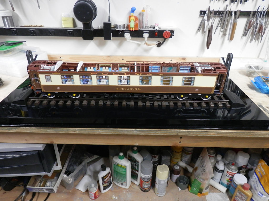


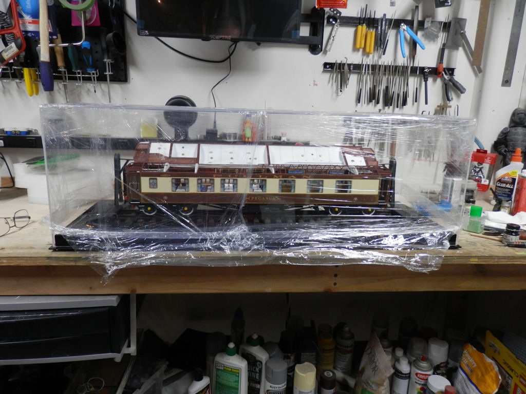

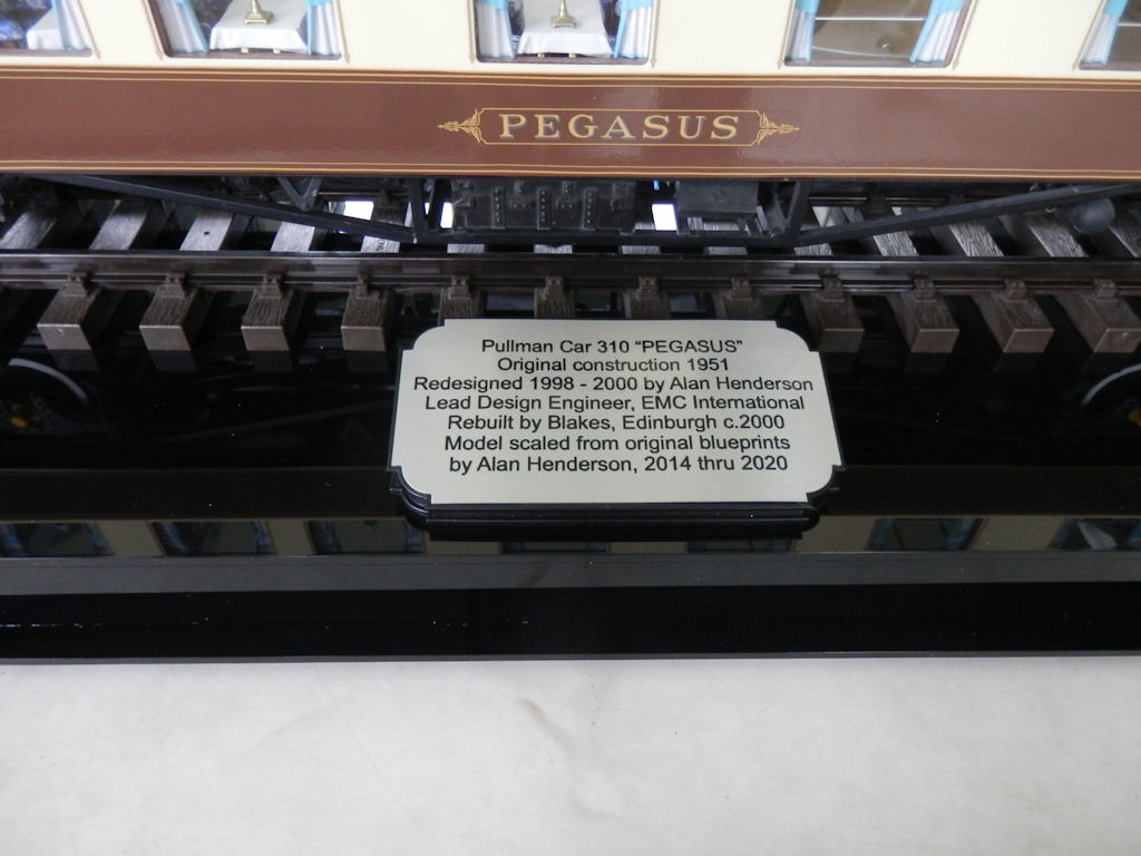


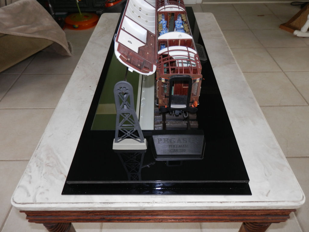

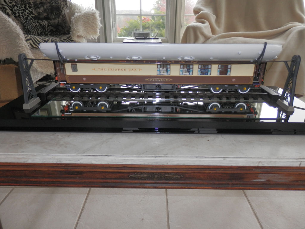
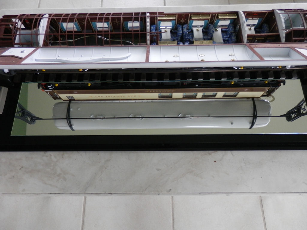
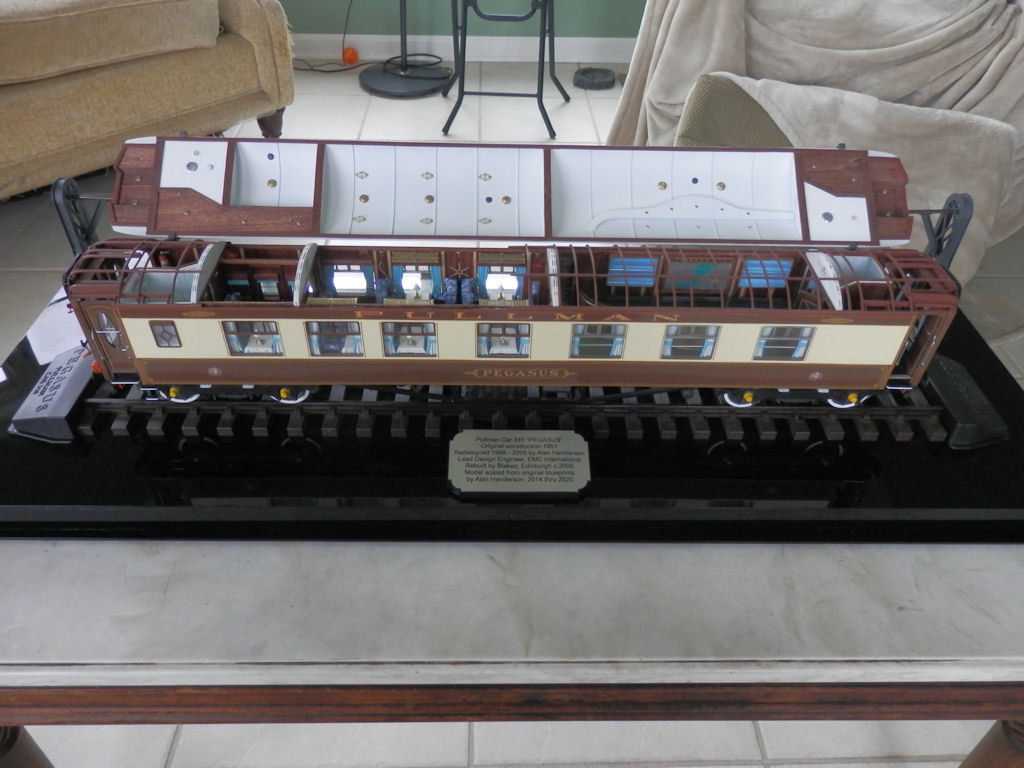


 The display case arrived


")


")


1951 Pullman Scratchbuild in 1/32
in Kitbuilding & Scratchbuilding
Posted · Edited by hendie
Hi Ian. I'd say it's going as per normal.
I'm in the middle of converting am old 1950's Revell H19 to a Westland Whirlwind HAR10, circa 1972
So far that has involved cutting off the tail to set it at the correct angle, scratch building: the cabin interior, the cockpit, an entirely new nose, the entire front and rear undercarriage, the tail pylon, replacing the kit transparencies, and vacforming a new windscreen and sliding doors.
I started this as a "fun" build
I still have to scratch a new rotor head and rotor blades, and no doubt a few other bits as well.
Oh, and 3d printed the wheels as the kit parts were not even remotely wheel shaped