


Jon Gridley
-
Posts
19 -
Joined
-
Last visited
Content Type
Profiles
Forums
Blogs
Gallery
Events
Exhibition Layout Details
Store
Posts posted by Jon Gridley
-
-
On 12/06/2020 at 21:26, delticman said:
I found that Phoenix Precision P323 Southern Dark Olive was quite close but needed a little blue added, so after experimenting I found that between 6 and 10ml of Revell SM350 (Dark Blue) added to a 50ml tin of the Phoenix Precision P323 gave about the correct shade.
Hope this is of use.
Regards,
Geoff

What did you used for the diagonal stripe?
-
On 29/01/2015 at 21:10, luce001 said:
Firstly I would like to thank Ray for his hard work in starting off this excellent post! also for Eric and friends for the various coding updates.. I have made a few changes to the code and managed to get a working turntable on my layout, including an OLED display to show the position and head/tail indication. I only have 4 positions on my turntable and I didn't use the servo brake or manual pot but left these functions in.
The display I used was a 1.3" I2C IIC Serial 128X64 OLED LCD LED Display Module Digital for Arduino W which can be obtained easily on eBay... the driver for this is U8glib.h https://code.google.com/p/u8glib/ and the other components as mentioned by others I ordered from Proto-pic.
The revised coding is as follows, pictures to follow...
Jonathan
////////////////////////////////////////////////////////////////////////////////
//
//   DCC Turntable Rev 17 9 Jan 2015
//   based on code from rmweb.co.uk forum - edited by J.Luce
//   Program functions:
//     "Real World" interface
//     2- N.O. Push buttons to enable move to "Head" or "Tail"
//     1- 10k Continuous turn POT to select track.
//     1- N.O. Reset button on fascia
//     Use digital inputs on 6 & 7 to stepforward and backward and
//       read out in the serial monitor so that you can program easier.
//     Release & Servo Brake function works with brake and release function.
//     Route positioning not taking shortest route to next location- (i.e. Tk.1 to Tk. 10 would be through 0)
//     Always approaches a track from the same direction to account for gear/mechanical lash/slop.
//       if the table was going CW to pos. 1 it approaches value B and stops
//       if the table was going CCW to Pos 1 it should go past B a (value B-X) and then go CW to B.
//     Added a (commented out)set up tool in the "loop" section of the code to set up the POT on the fascia panel.
//       this let's you align the POT to the markings on the panel.  Uncomment to use, then re-comment to hide.
//     Set up tool in the "loop" section of the code to set up the Brake Servo using the POT on the fascia panel.
//       this let's you find the optimal Release and Brake position for the servo brake.  Uncomment to use, then re-comment to hide.
//     Added u8g display to show track position and heading, initialise at startup
//     Move to track 0 "Head" at startup
////////////////////////////////////////////////////////////////////////////////

////////////////////////////////////////////////////////////////////////////////
//
// DCC Turntable Control Routines

#include <DCC_Decoder.h>
#include <AccelStepper.h>
#include <Wire.h>
#include <Adafruit_MotorShield.h>
#include "utility/Adafruit_PWMServoDriver.h"
#include <Servo.h>            //servo library reference
#include "U8glib.h"

// setup u8g object, please remove comment from one of the following constructor calls
// IMPORTANT NOTE: The following list is incomplete. The complete list of supported
// devices with all constructor calls is here: http://code.google.com/p/u8glib/wiki/device

U8GLIB_SH1106_128X64 u8g(U8G_I2C_OPT_DEV_0|U8G_I2C_OPT_FAST);	// Dev 0, Fast I2C / TWI

//////////////////////////////////////////////////////////////////////////////////////////////////////////////////////////////////////
//////////////////////////////////////////////////////////////////////////////////////////////////////////////////////////////////////
//
// Defines and structures
//
#define kDCC_INTERRUPT            0

typedef struct
{
    int               address;                // Address to respond to

} DCCAccessoryAddress;

DCCAccessoryAddress gAddresses[5];          // Allows 4 dcc addresses: [XX] = number of addresses you need (including 0).

const unsigned long releaseTimeout_ms = 2000;      //reduced to 2 seconds for now
const long MOTOR_STEP_COUNT = 200 * 16;	            //number of steps for a full rotation

//new stuff
boolean tableTargetHead = false;        //the new variable for Head/Tail Position either from DCC or Analog
int tableTargetPosition = 0;            //the new variable for Table Postition either from DCC or Analog
boolean newTargetLocation = false;
boolean buttonPushedHead = false;
boolean buttonPushedTail = false;
boolean inMotionToNewTarget = false;
boolean isReleased = false;		// isReleased tries to make sure the motor is not continuously released
unsigned long stepperLastMoveTime = 0;
const long MOTOR_OVERSHOOT = 10;        // the amount of overshoot/ lash correction when approaching from CCW
int overshootDestination = -1;

//Servo Stuff
Servo brakeservo;  // create servo object to control a servo
const int servoBrake = 9;  //value for brake position
const int servoRelease = 2;  //value for release position

//Programming button variables
boolean programmingMode = false;
boolean programmingModeMoveForward = true;	//If in programming mode, are we moving forward?
unsigned long programmingLastMoveMillis = 0;	//When was the last programming move done?
const int programRotateDelay = 100;			//Delay between steps in ms while holding button

//location variables
const int A = 144;          //TT Track 0-  Head
const int B = 328;          //TT Track 1-  Head
const int C = 482;          //TT Track 2-  Head
const int D = 632;          //TT Track 3-  Head
const int N = 1745;         //TT Track 0-  Tail
const int O = 1928;         //TT Track 1-  Tail
const int P = 2080;         //TT Track 2-  Tail
const int Q = 2230;         //TT Track 3-  Tail

const int PositionTrackHead[] = { A, B, C, D };
const int PositionTrackTail[] = { N, O, P, Q };

////////////////////////////////////////////////////////////////////////////////
////////////////////////////////////////////////////////////////////////////////
//
// Adafruit Setup

Adafruit_MotorShield AFMStop(0x60); // Default address, no jumpers

// Connect stepper with 200 steps per revolution (1.8 degree)
// to the M3, M4 terminals (blue,yellow,green,red)

Adafruit_StepperMotor *myStepper2 = AFMStop.getStepper(200, 2);

// you can change these to SINGLE, DOUBLE, INTERLEAVE or MICROSTEP!

// wrapper for the motor! (3200 Microsteps/revolution)
void forwardstep2() {
  myStepper2->onestep(BACKWARD, MICROSTEP);
}
void backwardstep2() {
  myStepper2->onestep(FORWARD, MICROSTEP);
}
void release2()   {
  myStepper2->release();
}

// Now we'll wrap the stepper in an AccelStepper object

AccelStepper stepper2 = AccelStepper(forwardstep2, backwardstep2);

//////////////////////////////////////////////////////////////////////////////////////////////////////////////////////////////////////
//////////////////////////////////////////////////////////////////////////////////////////////////////////////////////////////////////
//
// Decoder Initiation
//
void ConfigureDecoder()
{                                    //Put all the decoder #'s you need here.  Remember to change
                                     //DCCAccessoryAddress gAddresses[XX];(above) where XX = number of addresses you need.
    gAddresses[0].address = 200;
    gAddresses[1].address = 201;
    gAddresses[2].address = 202;
    gAddresses[3].address = 203;
}

//////////////////////////////////////////////////////////////////////////////////////////////////////////////////////////////////////
//////////////////////////////////////////////////////////////////////////////////////////////////////////////////////////////////////
//
// Basic accessory packet handler
//

void BasicAccDecoderPacket_Handler(int address, boolean activate, byte data)
{
        // Convert NMRA packet address format to human address
    address -= 1;
    address *= 4;
    address += 1;
    address += (data & 0x06) >> 1;

    boolean enable = (data & 0x01) ? 1 : 0;

    for(int i=0; i<(int)(sizeof(gAddresses)/sizeof(gAddresses[0])); i++)
    {
        if( address == gAddresses[i].address )
        {

            Serial.println("");
            Serial.print("DCC addr: ");
            Serial.print(address,DEC);
            Serial.print("   Head/Tail = (1/0) : ");
            Serial.println(enable,DEC);

			//new stuff
                        tableTargetHead = enable;
                        tableTargetPosition = i;

                        //picture loop
                        u8g.firstPage();
                        do {
                          draw(tableTargetPosition, tableTargetHead);
                        } while( u8g.nextPage() );

			//New packet and we have a new target location, set the flag
			newTargetLocation = true;
                        doStepperMove();

  			// old location for if/else statements
		}
	}
}

/////////////////////////////////////////////////////////////////////////////
//
//  draw ug8 display
//

void draw(int address, boolean enable) {
  // graphic commands to redraw the complete screen should be placed here
  u8g.setFont(u8g_font_unifont);
  u8g.setPrintPos(20, 25);
  u8g.print("Position ");
  u8g.print(address,DEC);
  u8g.setPrintPos(20, 45);
  if (enable)
  {
    u8g.print("Head");
  }
  else
  {
    u8g.print("Tail");
  }
  u8g.drawRFrame(0,0,128,64,8);
}

/////////////////////////////////////////////////////////////////////////////
//
//  readAnalogLocation() Reads the pot input on analog pin 1, displays some
//  information out the serial, and sets the target position variable
//

int readAnalogLocation()
{
	int potDisp = analogRead(1);
	int potOut = potDisp / 79; //1023 / 13

	Serial.println("");
        Serial.print("Analog Location: ");
	Serial.print("Track # ");
	Serial.print(potOut, DEC);
	Serial.print("   Head/Tail = (1/0) : ");
	Serial.println(tableTargetHead, DEC);

	//tableTargetPosition = potOut;
	return potOut;
}

//////////////////////////////////////////////////////////////////////////////////////////////////////////////////////////////////////
//////////////////////////////////////////////////////////////////////////////////////////////////////////////////////////////////////
//
// Subroutine: doStepperMove()
//	 Moves the stepper based on location inputs, calls up "SetStepperTargetLocation()"
//
///////////////////////////////////////

void doStepperMove()
{

        // Run the Stepper Motor //
        stepper2.run();

	boolean isInMotion = (abs(stepper2.distanceToGo()) > 0);
	boolean newTargetSet = false;

	// If there is a new target location, set the target
	if (newTargetLocation)
	{
		Serial.println("Moving to New Target Location...");
		SetStepperTargetLocation();
		newTargetSet = true;
	}

	if (inMotionToNewTarget)
	{
		if ((!isInMotion) && (!newTargetSet))
		{
			Serial.print("Not Moving!  DtG: ");
			Serial.print(stepper2.distanceToGo());
			Serial.print(" TP: ");
			Serial.print(stepper2.targetPosition());
			Serial.print(" CP: ");
			Serial.print(stepper2.currentPosition());
			Serial.print(" S: ");
			Serial.print(stepper2.speed());
			Serial.println();
		}
				//release the brake
                                brakeservo.write(servoRelease);
                                delay (5);
		inMotionToNewTarget = isInMotion;
	}
	else
	{
		if (programmingMode)
		{
			//If we are programming, do that move
				//release the brake
                                brakeservo.write(servoRelease);
                                delay (5);

                        if ((millis() - programmingLastMoveMillis) >= programRotateDelay)
			{
				programmingLastMoveMillis = millis();
				stepper2.move(programmingModeMoveForward ? 1 : -1);

                                Serial.println("");
				Serial.print("Programming mode, Current location: ");
				Serial.println(stepper2.currentPosition());
		                int potDisp = analogRead(1);
		                int potOut = potDisp / 79; //1023 / 13
		                Serial.print("Analog Location: ");
                                Serial.print("Track # ");
		                Serial.println(potOut, DEC);
		                delay(45);
			}
		}
		if ((stepper2.currentPosition() % MOTOR_STEP_COUNT) == 0)
		{
    		        //setCurrentPosition seems to always reset the position to 0, ignoring the parameter
			Serial.print("Current location: ");
			Serial.print(stepper2.currentPosition());
			Serial.println(" % STEPCOUNT.  Why here?");
		}
	}
                      //stepper timer subroutine came from here.
}

//////////////////////////////////////////////////////////////////////////////////////////////////////////////////////////////////////
//////////////////////////////////////////////////////////////////////////////////////////////////////////////////////////////////////
//
// Subroutine: SetStepperTargetLocation()
//     Takes the global variables: tableTargetHeadOrTail, and tableTargetPosition, and sets the stepper2
//   object moveTo() target position in steps-  inserts values back into "doStepperMove()"
//
///////////////////////////////////////

void SetStepperTargetLocation()
{
    int newTargetLoc = -1;
    if (tableTargetHead)
    {    //use head location variable
        {
            newTargetLoc = PositionTrackHead[tableTargetPosition];
            inMotionToNewTarget = true;
        }
    }
    else
    {    //use tail location variable
        {
            newTargetLoc = PositionTrackTail[tableTargetPosition];
            inMotionToNewTarget = true;
        }
    }

    if (newTargetLoc > 0)
    {
        int currentLoc = stepper2.currentPosition();
        int mainDiff = newTargetLoc - currentLoc;
        if (mainDiff > (MOTOR_STEP_COUNT / 2))
        {
            mainDiff = mainDiff - MOTOR_STEP_COUNT;
        }
        else if (mainDiff < (-MOTOR_STEP_COUNT / 2))
        {
            mainDiff = mainDiff + MOTOR_STEP_COUNT;
        }

        if (mainDiff < 0)
        {
            mainDiff -= MOTOR_OVERSHOOT;
            overshootDestination = MOTOR_OVERSHOOT;
        }
        stepper2.move(mainDiff);
    }
    programmingMode = false;
    newTargetLocation = false;
  }

//////////////////////////////////////////////////////////////////////////////////////////////////
//
//  Stepper Timer sub routine this runs from the main loop. It also supports the release function.
//
//////////////////////////////////////////////////////////////////////////////////////////////////

void stepperTimer()
{
    // Run the Stepper Motor //
    stepper2.run();

    boolean isInMotion = (abs(stepper2.distanceToGo()) > 0);
    //Check if we have any distance to move for release() timeout.  Can check the
    // buffered var isInMotion because we also check the other variables.
    if (isInMotion || programmingMode )
    {
        //We still have some distance to move, so reset the release timeout
        stepperLastMoveTime = millis();
        isReleased = false;
    }
    else
    {
        if (!isReleased)
        {
            if (overshootDestination > 0)
            {
                stepper2.move(overshootDestination);
                overshootDestination = -1;
            }
            if (((millis() - stepperLastMoveTime) >= releaseTimeout_ms))
            {
                //If isReleased, don't release again.
                isReleased = true;
                Serial.print ("Relative Current Position: ");
                Serial.print(stepper2.currentPosition());    //shows position the table thinks it is at (how it got here)

                int currentLoc = stepper2.currentPosition();    // Resets the positon to the actual positive number it should be
                currentLoc = currentLoc % MOTOR_STEP_COUNT;
                if (currentLoc < 0)
                {
                    currentLoc += MOTOR_STEP_COUNT;
                }
                stepper2.setCurrentPosition(currentLoc);
                stepper2.moveTo(currentLoc);

                Serial.print ("    Actual Current Position: ");
                Serial.println(stepper2.currentPosition());    // shows the position value corrected.

                //Set the servo brake
                brakeservo.write(servoBrake);
                delay(750);

                //release the motor
                release2();
                Serial.println("    Brake Set & Motor Released ");
            }
        }
    }
}

///////////////////////////////////////////////////////
//
//  Check Programming Buttons-  look for either of the programming buttons being pushed
//

void checkProgrammingButtons()
{
	programmingMode = false;
	bool buttonPushedProgUp = (digitalRead(6) == LOW);
	bool buttonPushedProgDown = (digitalRead(7) == LOW);

	//If one button is pushed, but not both
	if ((buttonPushedProgDown || buttonPushedProgUp) && !(buttonPushedProgDown && buttonPushedProgUp))
	{
		programmingMode = true;
		programmingModeMoveForward = buttonPushedProgUp;
	    doStepperMove();
        }
}

///////////////////////////////////////////////////////////////
// Manual move to using the pushbuttons and POT
//

void checkManualButtons()
{
	//Read the Head button input
	if (digitalRead(4) == LOW)
	{
		buttonPushedHead = true;
	}
	else if (buttonPushedHead)
	{
		//Button was pushed, but is not being pushed now
		//Clear pushed variable
		buttonPushedHead = false;
		//Set the target head variable
		tableTargetHead = true;
		//Read the analog location
		tableTargetPosition = readAnalogLocation();

		//Then set the new target flag
		newTargetLocation = true;
          doStepperMove();
	}

	//Read the Tail button input
	if (digitalRead(5) == LOW)
	{
		buttonPushedTail = true;
	}
	else if (buttonPushedTail)
	{
		//Button was pushed, but is not being pushed now
		//Clear pushed variable
		buttonPushedTail = false;
		//Set the target head variable
		tableTargetHead = false;
		//Read the analog location
		tableTargetPosition = readAnalogLocation();

		//Then set the new target flag
		newTargetLocation = true;
          doStepperMove();
	}
}

//////////////////////////////////////////////////////////////////////////////////////////////////////////////////////////////////////
//////////////////////////////////////////////////////////////////////////////////////////////////////////////////////////////////////
//
//
// Setup
//

void setup()
{
	Serial.begin(9600);

	AFMStop.begin(); // Start the shield

        //servo brake release before stepp moves
        brakeservo.attach(10);  // attaches the servo on pin 10 to the servo object
        brakeservo.write(servoRelease);
        delay (30);

        //initial display
        tableTargetHead = true;
        tableTargetPosition = 0;

        u8g.firstPage();
        do {
        draw(tableTargetPosition, tableTargetHead);
        } while( u8g.nextPage() );

	//configure pin3 as an input and enable the internal pull-up resistor
	pinMode(3, INPUT_PULLUP);		//Hall Effect sensor: to reset position on startup
	//configure pin4 as an input and enable the internal pull-up resistor
	pinMode(4, INPUT_PULLUP);		//Head button
	//configure pin5 as an input and enable the internal pull-up resistor
	pinMode(5, INPUT_PULLUP);		//Tail button
	//configure pin6 as an input and enable the internal pull-up resistor
	pinMode(6, INPUT_PULLUP);		//Programming: Move forward single step
	//configure pin7 as an input and enable the internal pull-up resistor
	pinMode(7, INPUT_PULLUP);		//Programming: Move reverse single step

	//read the sensoron Dig I/O #3 (open collector type- Hall Effect sensor) value into a variable
	int sensorVal = digitalRead(3);

	//set stepper motor speed and acceleration
	stepper2.setMaxSpeed(80.0);
	stepper2.setAcceleration(10.0);

	// if near reference point move away
	while (sensorVal == LOW) {
		sensorVal = digitalRead(3);
		forwardstep2();
		delay(25);
		Serial.println("Stepper Home");
	}

	// step backward to sensor index point
	while (sensorVal == HIGH) {
		sensorVal = digitalRead(3);
		backwardstep2();
		delay(50);
	}

        //when home- sets brake
        delay (500);
        brakeservo.write(servoBrake);

       //initial track position 0 head
       newTargetLocation = true;
       doStepperMove();


   DCC.SetBasicAccessoryDecoderPacketHandler(BasicAccDecoderPacket_Handler, true);
   ConfigureDecoder();
   DCC.SetupDecoder( 0x00, 0x00, kDCC_INTERRUPT );
}

//////////////////////////////////////////////////////////////////////////////////////////////////////////////////////////////////////
//////////////////////////////////////////////////////////////////////////////////////////////////////////////////////////////////////
//
// Main loop
//

void loop()
{
   static int addr = 0;

        ////////////////////////////////////////////////////////////////
        // Loop DCC library

    DCC.loop();

        ////////////////////////////////////////////////////////////////
        // Bump to next address to test
    if( ++addr >= (int)(sizeof(gAddresses)/sizeof(gAddresses[0])) )
    {
        addr = 0;
    }

	//~~~~~~~~~~~~~~~~~~~~~~~~~~~~~~
	//~~~~~~~~~~~~~~~~~~~~~~~~~~~~~~
	//  To configure the POT (uncomment this text)
	//configure alalog pin 1 as an input

        //  int potDisp = analogRead(1);
	//
	//  int potOut = potDisp / 79; //1023 / 13
	//     delay(1000);
	//     Serial.print("Analog Location: ");
	//     Serial.println(potOut);

        // end of POT configuration- re-comment this section to hide during normal use
	//~~~~~~~~~~~~~~~~~~~~~~~~~~~~~~~
	//~~~~~~~~~~~~~~~~~~~~~~~~~~~~~~


	//~~~~~~~~~~~~~~~~~~~~~~~~~~~~~~
	//~~~~~~~~~~~~~~~~~~~~~~~~~~~~~~
	//  To configure the Servo Brake (uncomment this text)
	//configure alalog pin 1 as an input

        //    int potDisp = analogRead(1);            // reads the value of the potentiometer (value between 0 and 1023)
        //    int potOut = map(potDisp, 0, 1023, 0, 50);     // scale it to use it with the servo (value between 0 and 180)
        //    brakeservo.write(potOut);                  // sets the servo position according to the scaled value
        //    delay(1000);
	//    Serial.print("Servo Position Value: ");
	//    Serial.println(potOut);

	// end of POT configuration- re-comment this section to hide during normal use
	//~~~~~~~~~~~~~~~~~~~~~~~~~~~~~~~
	//~~~~~~~~~~~~~~~~~~~~~~~~~~~~~~

	//Tests to see if the manual move buttons are pressed, if so set the needed flags
          checkManualButtons();

	//Checks the programming buttons, if depressed then set the right flags
          checkProgrammingButtons();

	//StepperAccel.Run() in this function
          stepperTimer();

}
Good Evening, i am wanting to use this code, i have replaced my adafruit shield with a 'all in one' shield with the dcc decoder built in. it has a A4988 driver installed.
Can Anyone advise how i can modify the code to work with the A4988 driver rather than the adafruit sheild, i realise the servo stuff will need to be changed but i can do that, i'm just struggling to get my head around the stepper side of the coding as the attached code uses both the adafruit and accelstepper libaries.
my stepper is currently setup as AccelStepper stepper1(1, 5, 4); on the example code from dccinterfaces.
i'm running a 5:1 reduction from the stepper. (16t to 80t)

-
 2
2
-
-
I'm currently re-working my turntable from been mounted on top of the stepper to having a belt drive located under the table.
It's made of 10mm aluminium its not the neatest but its my first every attempt at using my micro mill.
There are three top hat bearings in the assembly two back to back on the main plate and a third in the support under the main gear. I'm using a 4:1 ratio. Should allow for some lovely fine indexing
-
1
-
 4
4
-
-
On 17/04/2018 at 09:37, ianjeffery said:
Just a quick update on this...
I'm currently working on a touch screen interface to supplement the DCC control.
Any update on this Ian? I’d be really interested.
on a side note has anyone worked on a sketch to be able to program the roads into the eeprom memory via a keypad?
-
I love the Lima 09s, I’ve about 8 of them, although one is wearing a Hornby body as the Lima chassis is nice than the steam loco chassis Hornby used with the odd wheel set spacing. I don’t think I paid more than about £12 for any of them, I’ve attached a photo of my 13 but made with Lima 09s, I’m going to be running auto decoupling via a decoder in the master and sound with a speaker in each from the slave. They were both driven but I found you get some hunting so the slave now is just weighted but not driven. She’s also running a CD player motor and has a lovely slow crawl
-
4
-
2
-
-
On 31/03/2015 at 16:26, Pete Harvey said:
I would be happy to look at other engines and traction motors if modelers want them?
The book I have that has the drawing of the engine in it (Author O.S.Nock) references the engine and being used in the 47 and does not mention the 48 but some one I showed it to said "why have you done an engine for a 48" that's why it says "4mm Sulzer Class 47/48 Engine" but they are basically the same engine as far as I can find out just with a few more bits on the top & as I have said in the corner of a Depot or under a mucky tarp who will be that bothered, as it fits in with the location.
Pete
I saw somewhere not sure if it was this post or another several asked about the EE 6KT, i have some drawings that may be of use?
-
Wow thank you guys, love the pic of the 09? With the body removed. I'll have a look and those links and the book, for me it's just a fun little project to really get to grips with 3d modeling so far I've stuck to simple things like mounts for ipad on my drone controller, and speaker boxes for dcc.
-
I'm trying to hunt down any profile style drawings of a 6kt, even side on, front on photos would be of help.
i'm planning to model one in cad to 3d print, once done the plan is to put on thingiverse so that it is there for all to use/print
I have several 08's and 09's plus a 13 so thought a 6KT would be a fitting addition
Jon

-
That's would be awesome ray
-
Hi All,
Just thought i'd post a picture of the latest project i'm working on.
This turntable project uses the same DCC interface and reference sensor (yet to be connected) as before but utilises the Arduino Nano and A4988 Stepper Driver. A version of the PCB is available from DCCinterface.com either as a PCB only or fully populated board. Also an off the shelf display/keyboard has been attached to the I2C pins of the Nano.
This will give manual control of up to 100 stations on the turntable making this suitable for DC users.
Of course DCC users can use as before by sending a DCC Accessory command via the DCC interface (as well as manual control).
Instead of a direct drive to the turntable, this time i'm using a toothed belt with 4:1 ratio (20:80) pulleys and a slimline stepper as it has to fit under a shallow exhibition baseboard.
Most of the code has been written and tested, just waiting for my new turntable kit to arrive so i can get it built up. Will post a video of progress so far later.
Ray.
Ray where did you source the belt drive from?, i had a look at your other thread, i like that the shaft is then supported above and below the large gear
-
just thought id upload some more pictures of my touch screen interface for the turntable...
the main screen
this is the 1st settings screen..The system uses the I2C interface to send commands, so hopefully should be easy to use for other projects too.
Wow that looks nice Ian, are you planning to sell kits for the touchscreen?, will it be able to store locations?
i got my turntable working on my test board, (scratch built with a copper clad board with bits of Dapol kit) using one of the earlier sketches can't think which atm. i really do need to get back on it hence checking the updates on thread.
i got around power by making a 360 degree ring with two contacts (one for each rail) then in the code one of the arduino pins flips depending on if the table is at head or tail (depending on output polarity) at the moment this is an additional line on each position/road in the code in turn this pin is switching a dpdt relay flipping the polarity to make sure its correct, this happend so quick the sound locos don't seem to notice

the other mod i had was to use the servo output in a previous sketch to move a micor servo to position a small rubber against my contact ring just to prevent drift when the motor was off, i#m going to be building up another tt soon, so defo going to get one of your kits ian, might actually get two and swap out all the boards on my first, its a much tidier solution.
Jon
-
https://hackaday.io/project/11224-mechaduino thought this may be of interest?, it allows very accurate posistioning along with constant posistion checking effectively turning out stepper motors into 360 degree servos
reading the various wlak throughs it uses a magnet on the end of the stepper shaft and a magnetic rotarty encoder on the board, the calibration routine producting 16,384 entries for posisioning!-
1
-
-
I'm just wondering has anyone tried setting this style of turntable up with rocrail? I've got mine working nicely just want to get it setup in software now.
-
i think the whine is inherent of the stepper motors, the rev 17 software powers down the stepper after it has rotated, it also has a provision for a servo brake which i intend to use, i'm just going to make a foot shape on a bit of rod to push against the opposite side of my contact plate to act as a brake.
on a separate note, i'd have a good play and using a relay controlled by the Arduino works perfectly
started building up the rest of the bridge now
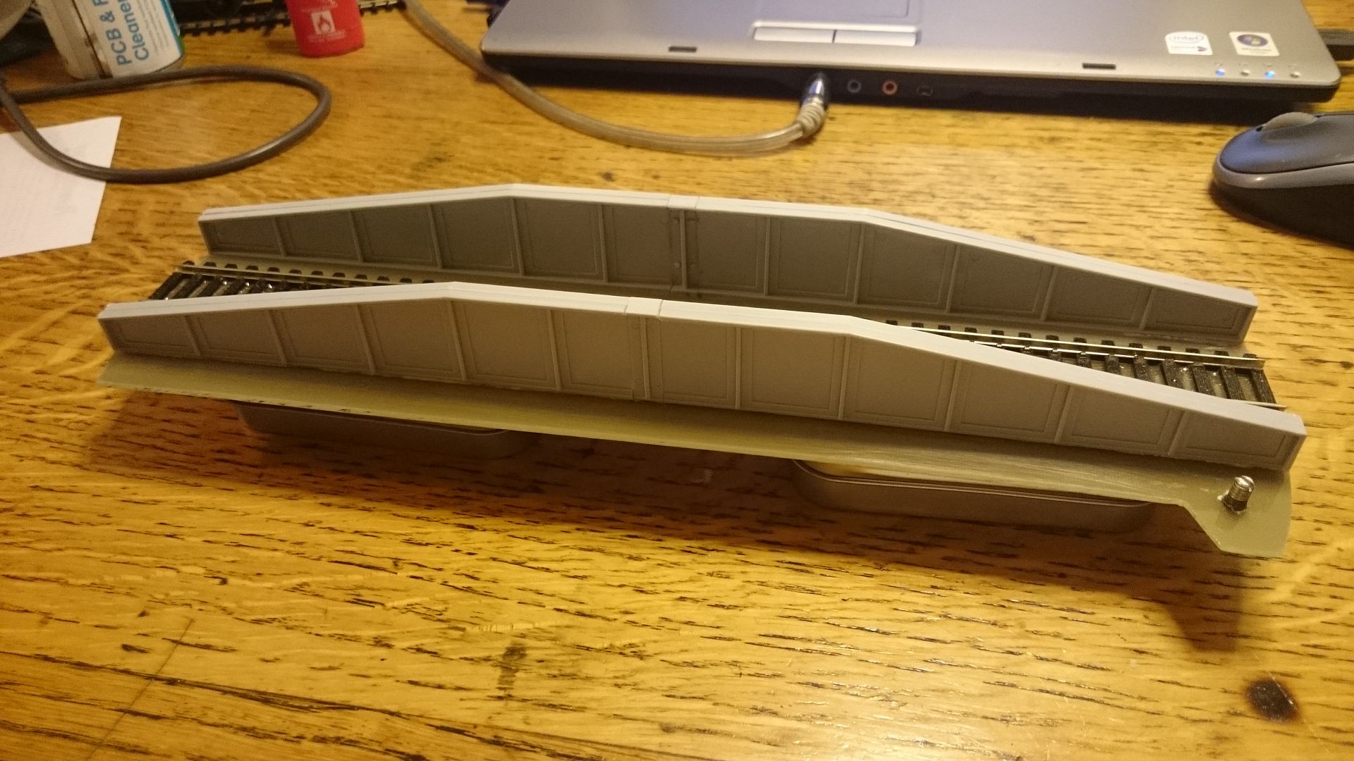
-
I have the libraries stored on my dropbox, i did find i have to alter the the name of the stepper driver library. here is the link.
https://www.dropbox.com/sh/o15rm6xz8iqp1uv/AADNfGefgdrStUCukmjWqVgJa?dl=0
I have also had a good play about, at the moment i have hacked the merg reverse loop module to allow me to controll the relay remotely, just to check all works, then i'll mount my relay and a control transistor on to a bit of strip board. i have added the following code to the bottom of the 'steppertimer' routine. line 420 this is using Rev 17 of the code by Luce001 in post #155 don't forget to add 'pinMode(8, OUTPUT) in the setup routine.
//New section to read direction bed is facing and invert the polarity if needed. //pinMode(8, OUTPUT) also added to void setup() if (tableTargetHead) { //use head location variable { digitalWrite(8, HIGH); Serial.println(" DCC Polarity Relay activated "); } } else { //use tail location variable { digitalWrite(8, LOW); Serial.println(" DCC Polarity Relay deactivated "); } } -
have you tried the sensor the other way up, when i was playing with mine i found it only works around one way, i removed the outer plastic and heat shrunk it to make it smaller.
in regards to the reversing module although simple in installation I'm building to a budget and can't justify buying a £90 reversing module when a DPDT relay costs less then £5, i'm sure its a easy mod in the software but not 100% sure how, it means then it will seemlessly flip the track polarity as the bridge rotates
-
yes DCC, no break in the contacts, i've popped the bridge off and taken a couple shots, it does it ramdomly, think the reverse module is too sensitive, it'll even to it whilst rotating with a loco on. i plan to use a simple double pole double throw relay, i allready have the relay and the hardware side is easy, i just need to know how to modify the code to switch the relay when the bridge is 180 degrees out.
Jon
-
Good evening all.
I'm new to the forum having stumbled across it whilst searching how to build a dcc turntable.
I studied electrical enginnering at college many years ago although now only used a hobby, i'm learning arduinos but keep getting distracted by projects.
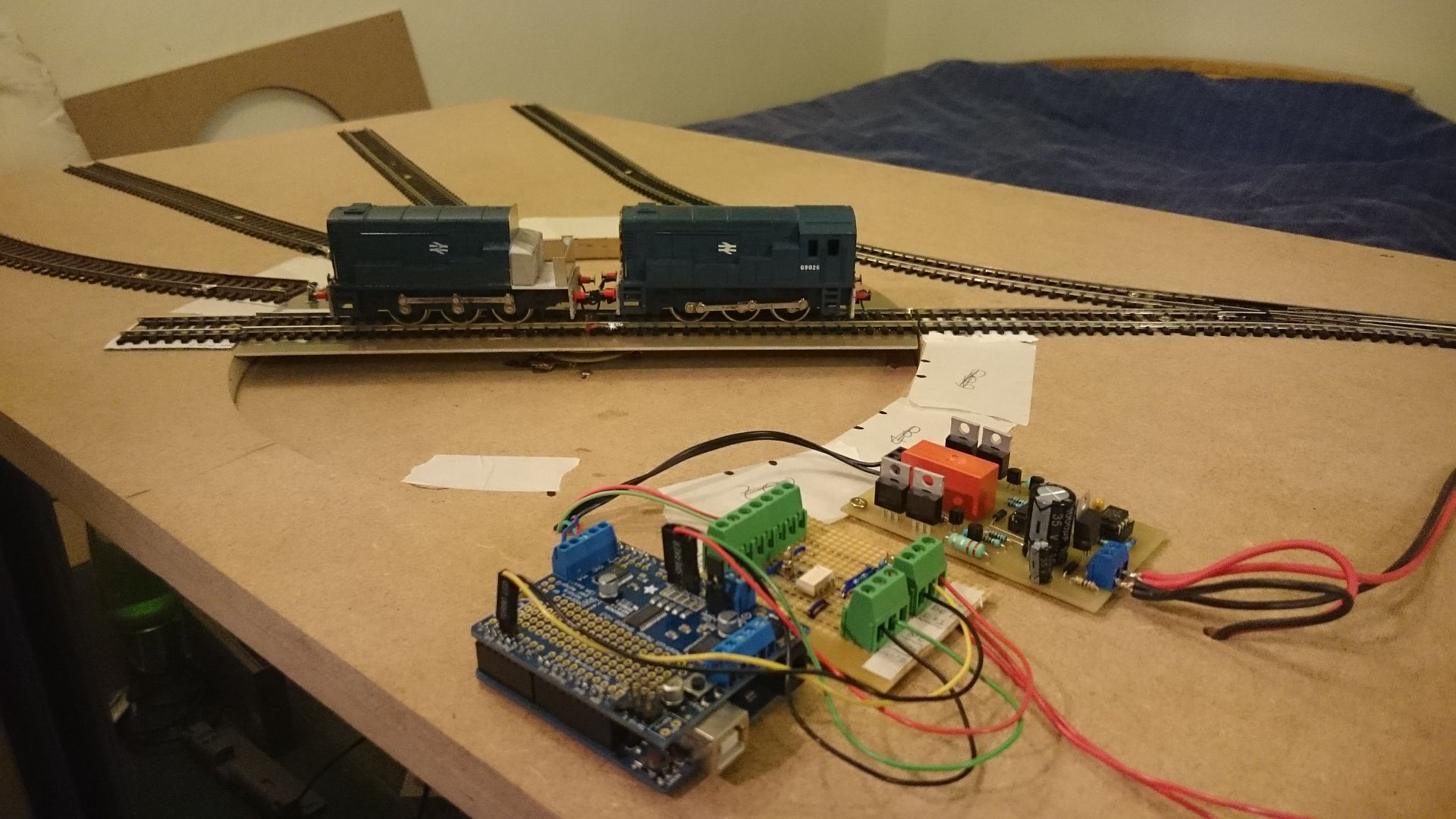
i'm also new to model rail, and am building a layout along with my dad, brother and uncle, at this stage i'm mocking up the turntable on a board for testing, i have followed through the first few pages (thank you so much for the easy to follow guide) and i'm now up to rev 17. i have the screen but have yet to connect it.
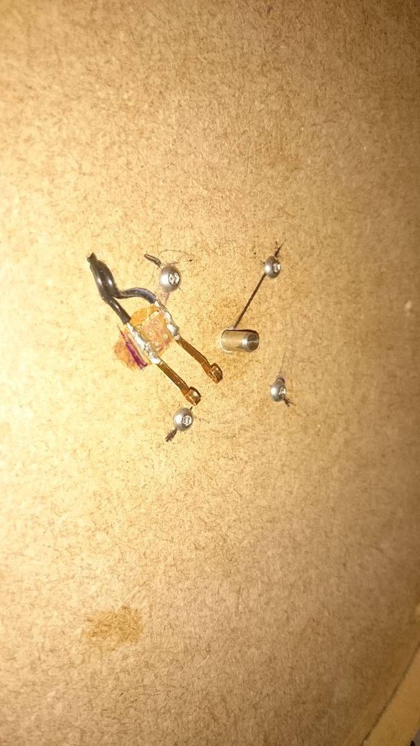
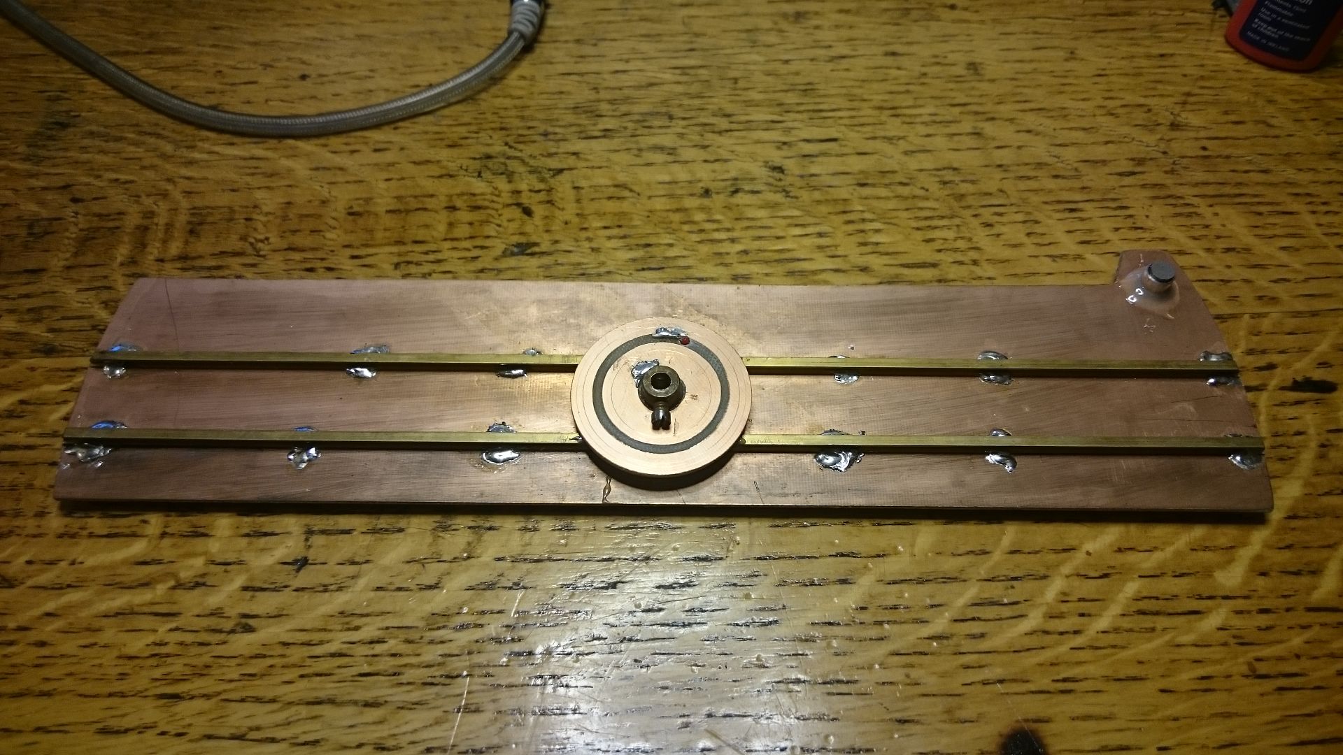
the turntable is based on a Dapol kit as its a style similar to the local area (west somerset railway) although the deck is now made from copper clad board with brass I beam to add support and height in the middle, attached to which is a mecano bush wheel drilled out to clamp directly to my stepper motor which has bearings much the same as i was planning to use.
under the bush wheel is a simple two track contact disk made from copper clad (35mm hole saw to seperate tracks (only through copper) and 52mm to cut out the disk. contacts is made via wipers with rolled ends made from normal pickup type strip.
now i've tried using a reversing loop module (merg type) but it keeps tripping, it i connect directly sound loco works fine for 360degrees plus without tripping the controller.
I also plan to use a servo brake and build a control box with a rotating switch and resister ladder rather then a pot. I post up photos of the underside of the bridge when i next take it off. also have a nice idea for wooden decking that should look very realistic
what i would like to do is be able to toggle a output to switch a relay to invert the track polarity depending on the direction of the table. could someone please point me in the right direction of how to add this (code wise, hardware i'm fine with)
Jon
-
2
-


GWR (2015) green paint?
in Modelling Questions, Help and Tips
Posted
Thank you Geoff, yea I get that’s pretty annoying, wouldn’t be as bad if you could get hold of the nozzles