


posneg6
-
Posts
82 -
Joined
-
Last visited
Content Type
Profiles
Forums
Blogs
Gallery
Events
Exhibition Layout Details
Store
Posts posted by posneg6
-
-
Thanks Nigel Cliffe, My mistake on CV 65v I got confused it was CV 60 and it did make a difference to my other 2 function wires that are for cab light and fire box. And I do use JMRI Decoder Pro but I find the Swiss mapping confusing I'm OK with the function map.
I think I'l just add a half watt 2 k resistor between the decoder blue wire and the Lais resistor board that should do the trick then reset CV 60 so I can see the cab and firebox lights.
I've tried to understand the Zimo manual pages 37&38 but just can't get my head around it.
Cheers
-
Zimo MS480 Protodrive sound decoder
Hi All, I've got a little problem trying to dim my forward and rear direction LEDs (FO) and I can't find a specific answer on Chat GTP! (or my supplier) it gave me CV 65 for the other function wire green and brown which which are connected to my Firefox glow and Cab light separately. I'm using the white wire for the forward direction lights and the yellow wire for the reverse direction `lights and they work fine but they are so bright. I'm using the LAIS resistor board as you can see in the picture. Each lamp has its own 1K Ohm 1/8W SMD resistors resistor, but they're still very bright. Can anybody point me in the right direction please.
The Loco is a Bachmann London Transport 57xx with Digitrains sound file which is amazing. loving the brake function, also installed a sugar cube speaker with 3D resonator plus LAIS stay alive lite 3.
Any help would be much appreciated.
Cheers.

-
 I found this postcard on the back it's written 0-6-0 No L30. at Olympia. I hope this helps
-
 2
2
-
-
I think that the Rapido WR16 XX is a fantastic model it runs extremely well until I put a Zimo MS590N18, pre loaded with YouChoose sound file. The main issue is that when I increase the speed above half way the train will not respond to any command or decrease speed after this, it seems locked in and will carry on no matter what I do with the controller, the only way to reset it is to remove it from the tracks or stop the whole system then restart. this has been going on for 2 months now so I decided to take the decoder out and swap it with another zimo non sound decoder. The Rapido runs as expected with a normal Zimo decoder. I have put the Zimo sound decoder into a Bachmann J 72 steam loco with built-in speaker and LED firebox. same problem.
I wrote to Rapido who replied with this ;
"As far as I have managed to work out, the 16xx is not compatible with Zimo, it was designed to take an ESU decoder and as a result it can behave erratically with Zimo decoders. I understand many Zimo users have removed the PCB and hard wired the model to get it to work.
I have sent the decoder back to my supplier here in Australia and he is running tests but so far unable to find fault in the decoder.
It looks like I will have to buy a Next 18 Breakout board and remove the Rapido PCB.
Keeping my fingers crossed that the new Zimo MS590N18, pre loaded with YouChoose sound file for the J72 will work without a problem.
Before you say get an ESU decoder, apparently there is a shortage of them at the moment in Australia.
-
 2
2
-
-
Hi People. I have just installed my first stay alive on my first sound loco. the loco is a Hornby Black 5 with a Hornby TSS sound decoder, then I added a 
Lais Dcc Stay Alive Lite 2. I am impressed with the lot. great loud sound and the stay alive is a total game changer.My next challenge is to instal a LaisDcc Stay Alive Lite 3 onto a TCS DP@x-UK non sound decoder! I have searched the interwebs and this site and emails TCS, to no avail, looking for the rectifier pads to solder onto. My question is does anyone know the correct pads to solder to?
Thanks in advance.
Stay safe and stay alive
")

-
Thanks for everyones help .
-
39 minutes ago, Pete the Elaner said:
I completely agree.
Information in wikis are added by contributors like you & me. Nobody really knows who has added what. They are great that if you see anything you know is wrong, you can simply correct it, so the information will have come from more than one person, which is great. The problem is that if I see something I BELIEVE is wrong, I can update it with what I BELIEVE is correct. If I am mistaken, then I will have updated the wiki with incorrect information.
If you are able to connect a PC, Mac or Linux machine to your Z21, then I recommend JMRI. It is written by enthusiasts for enthusiasts.
Instead of changing things by their bits, it gives them in plain English, like a check box for allowing DC running & radio buttons to choose whether you use long or short addresses (& you can obviously read the addresses) Adjusting sound volumes is simply a matter of moving sliders.. It will even give you CV values in decimal if you want to see them all listed.
I can't remember the last time I programmed something with a handset. Much easier to use JMRI on the PC & it automatically keeps a record of my CVs so if someone at the club changes some (which has happened), I can just re-apply them.
Thanks I'll have a look at it. I must say that I find it's all getting very much over complex for me. a comparison that makes sense to me as I'm an electrician is the smart wiring in homes, I did a smart home in Palm beach a few years ago it cost $50,000 for the equipment and caused a lot of problems for the owner who range me and said "I just want to turn a bloody ceiling fan on and now every light in the house is flashing the pool cover is opening and closing as are the garage doors!". I like to keep thing simple cause I'm simple.
-
1
-
-
Thanks for everyones help and suggestions. I have exhausted the variations in CV 29. so I'm back to the drawing board with my Stay alive units. I'm a very tactile electrician, I have no training in electronics but I am slowly learning. I will as suggested buy a couple of ready made stay alives to prove that they will work on my system, However I get a lot of satisfaction from making things and the cost of 40 RTR stay alives is more than I can afford when I can get 20 Tantalum caps for a few bucks.
Many thanks for all the help offered, what a great knowledge bank this is.
A work in progress.
-
10 hours ago, jpendle said:
Assuming that you are using the Z21 app, then it gives you the option to change any individual bit in CV29 without you having to do any calculations.
In the app, read CV29, then change the DC operation bit to 0 and write it back to the decoder.
Regards,
John P
Sorry you lost me when you said Assuming, Sadly all this Bit and Byte stuff is not a natural thing for me, it literally makes my brain hurt. Give me a tricky 3 phase 440Volt switchboard to fix and I'm happy.
-
1
-
-
2 minutes ago, RAF96 said:
You cannot ‘disable’ CV29. What you are being advised to do is disable DC running in CV29.
The simplest way is to use a CV29 calculator to find out the decimal number to write to it.
see here...
http://www.2mm.org.uk/articles/cv29 calculator.htm
Brilliant, Thanks for that I'll try 6 in cv29 see if that works. If not I'll use a long stick to prod the locos when they stall on points.
Thanks fo your help.
-
Hi In Wiki DCC Energy Storage it says
CV Changes
For proper operation, disable the Analog Conversion mode (in CV29), and set the packet timeout value in CV11 to "0." I read that elsewhere too. -
15 minutes ago, Nigelcliffe said:
Article on CV29, written years ago. I really should have put a penny-per-view on it to fund buying live-steam locos....
http://www.2mm.org.uk/articles/cv29 calculator.htm
You don't "disable CV29". You might want to use CV29 to disable DC operation of the locomotive.
Hi Hi I've been told to Disable CV 29 to enable stay alives to work.
-
Hi knowledgable ones, I'm stuck on trying to get my stay alive's working. I read in a few different places that I have to change value in CV11 to "0." and I managed that, however how do I disable CV 29? but I can't find out how to do that?
I've constructed a a couple of different Stay alive's and they hold a charge long enough to keep a 9V LED torch going for a few seconds.
The two different Stay alive's are as follows;
8 x 220uf @25volt Tantalum caps in parallel, effectively 1,760uf. connected to TCS T1blue and black stay alive wires.
the other is 2x 2,200uf 16volt poly caps in parallel, effectively 4,400uf soldered to blue and black contacts on the decoder socket.
My system is Rocco z21 the white one. the track voltage is 17.9 volts. Thats why I really should be using 20 or 25 volt caps.
I hope there is a simple answer but I won't hold my breath, I can't really get my head around packets and bits an bytes.
With Rocco nothing is easy Touchwood! Cheers in advance
-
On 12/06/2021 at 07:31, pygmalion said:
OK folks, I have finally reached stay-alive experiments.
I made 4400uF stay-alive (2x2200uF) for my 860014 LaisDCC decoder with black and blue stay-alive wires.
I also forgot to turn off DC (CV29 = 38) so the decoder was just acting all crazy. After I turned off DC (CV29 = 34), the decoder works normally, but the effect of stay-alive is ZERO. After the line loses power, the motor and/or LED stop immediately.
I know that the motor should only work for a fraction of a second, but I expected LED to work for at least a second.
I checked my stay-alive against LED and LED is kept on for a few seconds. I measured the voltage on the stay-alive while it was mounted on the decoder, and the voltage slowly drops after I turn off the power, but LED stops immediately.
Now I'm am clueless. Either I damaged LaisDCC somehow by providing stay-alive with DC turned on, or the decoder is just a piece of junk.
Does anyone have any ideas on this?Hi, Did you get any answers to this? I'm trying work out how to disable CV29 and I don't really understand how.
-
2 hours ago, Andymsa said:
This is a bit out there and no jokes plz lol. After laying the ballast I dry brush any excess off the sleepers, and now for the weird bit I use a speed adjustable bullet sex toy. The motor is removed from the inside of the toy, I found that the high frequency of vibration is just right as the ballast just bounces off the sleepers. You just allow the motor to vibrate on the rail and also tamps down the ballast. You could use an electric toothbrush brush if your screamish about such things as sex toys.
Strangely I don't have one of those in my tool kit, I'll ask the wife. however I do have a pair of crutch-less knickers that I could sieve the ballast through.
Just a bit of fun.
-
 1
1
-
-
Show your ballasting tricks and tips.
I've just completed my first station ballast job in years using a ballast spreader. I think it's a bit rubbish! too much ballast on the sleepers.
Would love to see how you do yours.
-
1
-
-
1 hour ago, posneg6 said:
Thanks for those links . I've seen them both. I still need to know what the the polarity of the blue and black wires are from my DCC concets decoder . It says nothing about that in their 12 page decoder manual
Hi, Sorted by using my multi meter, Blue is positive black is negative on the DCC TS4sax
-
Thanks for those links . I've seen them both. I still need to know what the the polarity of the blue and black wires are from my DCC concets decoder . It says nothing about that in their 12 page decoder manual
-
On 14/01/2019 at 06:38, Art Dent said:
In a previous thread, I had discussed my thoughts on fabricating a small stay-alive unit using super-capacitors.
This was prompted by me buying my 3-y-o grandson a 'Percy' 0-4-0 locomotive (and me not wanting it to stall on pointwork it only being a SWB 0-4-0).
Over the last couple of weeks I have refined my ideas and the design whilst trying to source the components.
When fitting a stay-alive - one if the biggest dangers (as I see it now) is to go for 'The Best Bang for Your Buck' - in other words, the biggest stay-alive you can fit (in terms of capacity) in a given space and for reasonable cost.
As 'Percy' isn't what you'd call a 'highly detailed' nor expensive model, so I didn't want to fit an overly-expensive decoder or stay-alive. This lead me to buying and trying a LaisDCC 860012 NEM651 + 2 stay-alive wires decoder and two LaisDCC Stay-alives ('small' 860007 and 'large' 860009). The decoder is less than £10, the small stay-alive (don't bother with it) is £3 and the large stay-alive (huge over-kill) is £9.00
More about the LaisDCC Decoder and Stay-Alives later.
To make sure that you don't encounter problems (like the loco taking off at high speed or running backwards - or both) when track power is cut, disable DC running in CV29
Anyway, to the main course ...
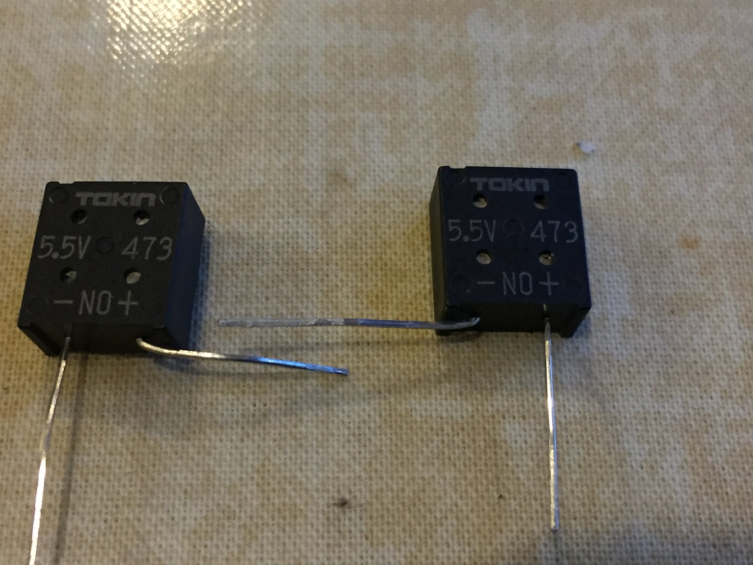
I had managed to find some 470,000uF, 5.5V rectangular supercapacitors. Three wired up in series would give a 16.5V, 157,000uF unit.
Fabrication of the 15.7mF (15700uF) stay-alive unit.My aim was to arrange these rectangular capacitors side-by-side so first I bent the negative and positive of adjacent capacitors at right-angles:
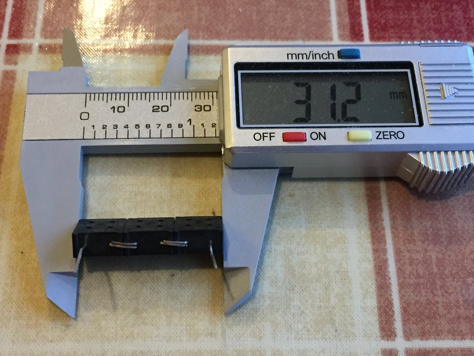
The legs were then angled slightly before the legs were cut to length and the capacitors were superglued together:
The first two capacitors were super-glued together ready to be soldered:
Then three capacitors were glued together ready to be soldered in series. This gives a maximum voltage that the stay-alive can handle of 16.5V and a capacity of 15700uF.It also makes for a relatively compact unit.
Another view of the 15700uF stay-alive unit:
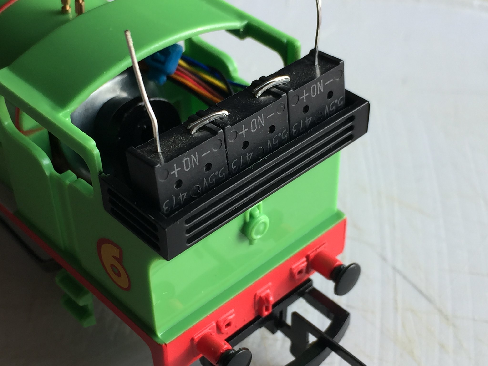
Checking for fit inside Percy's bunker (it only just fits):
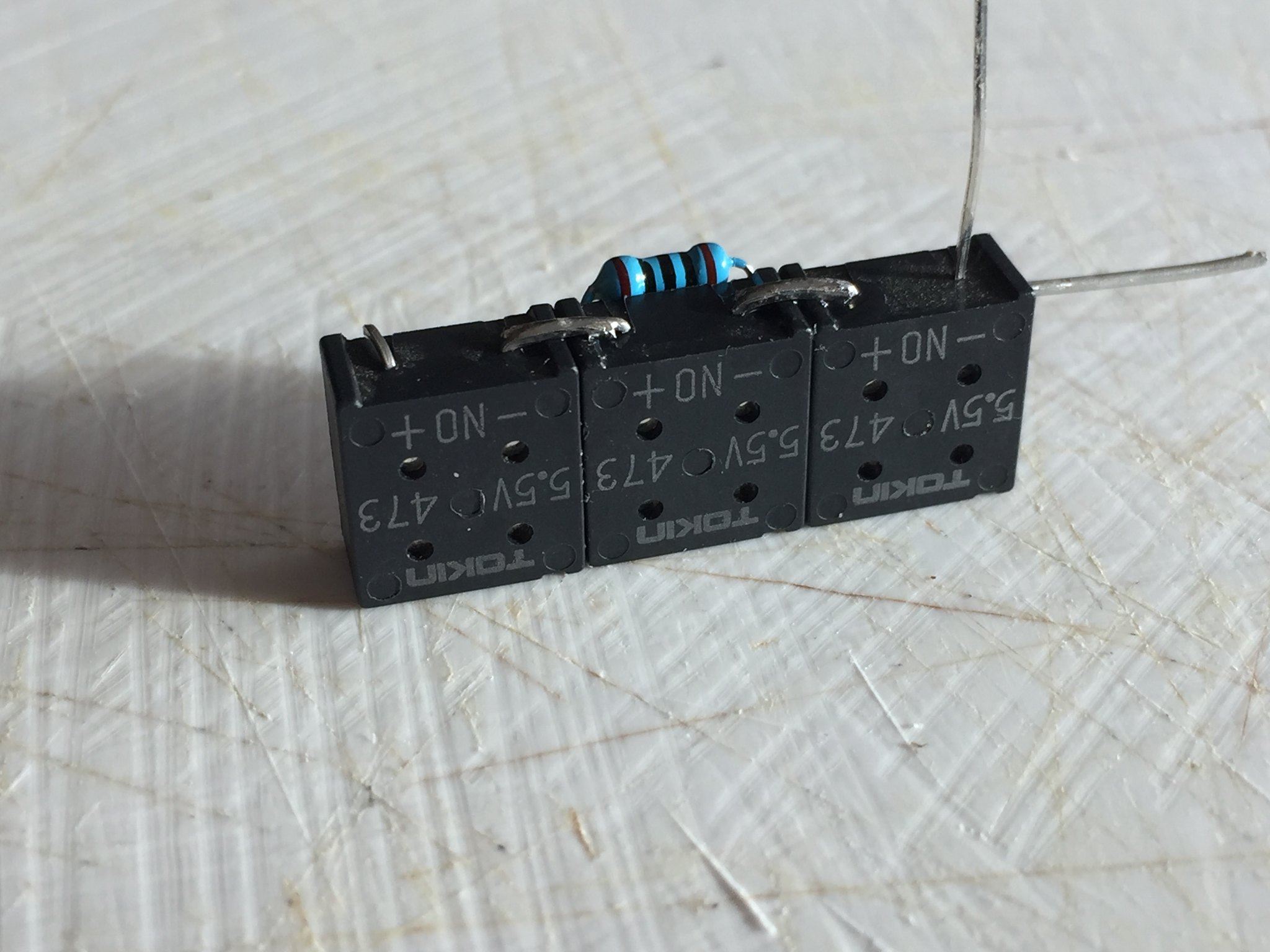
Capacitors soldered together and the discharging diode and charging resistor soldered:
Another view:
All-important insulation added:
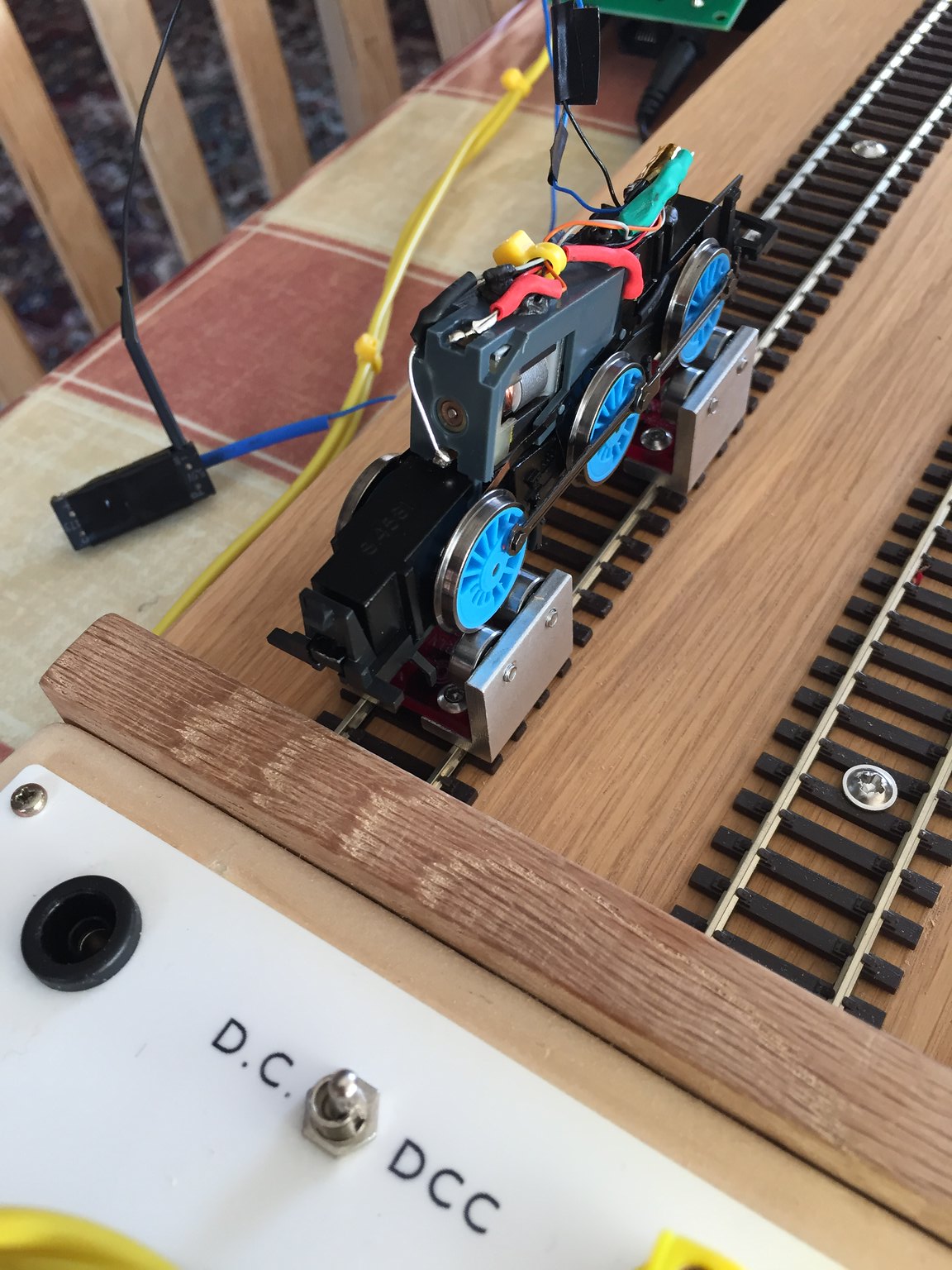
First testing (using cheap LaisDCC decoder rather than anything more expensive and some very Heath-Robinson wiring) as currently fitted to Thomas:
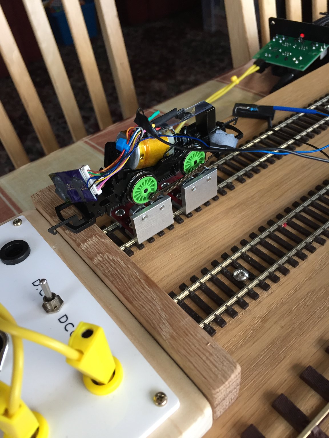
I ran Thomas ran for 5 mins at 75% throttle to ensure stay-alive is fully charged (not having previously calculated the time that a full charge would take).Upon disconnecting track power (using the centre-off switch you can see on the white panel) ...... NOTHING!No indication at all that the stay-alive is doing anything at all. The wheels just stopped dead.So, is the stay-alive not charging or is it a problem with the LaisDCC Decoder (and yes, DC running has already been turned off in CV29).I thought it was the decoder, so onto Percy with the DCC Concepts Zen 218 decoder ...Percy on the rolling road with the stay-alive:
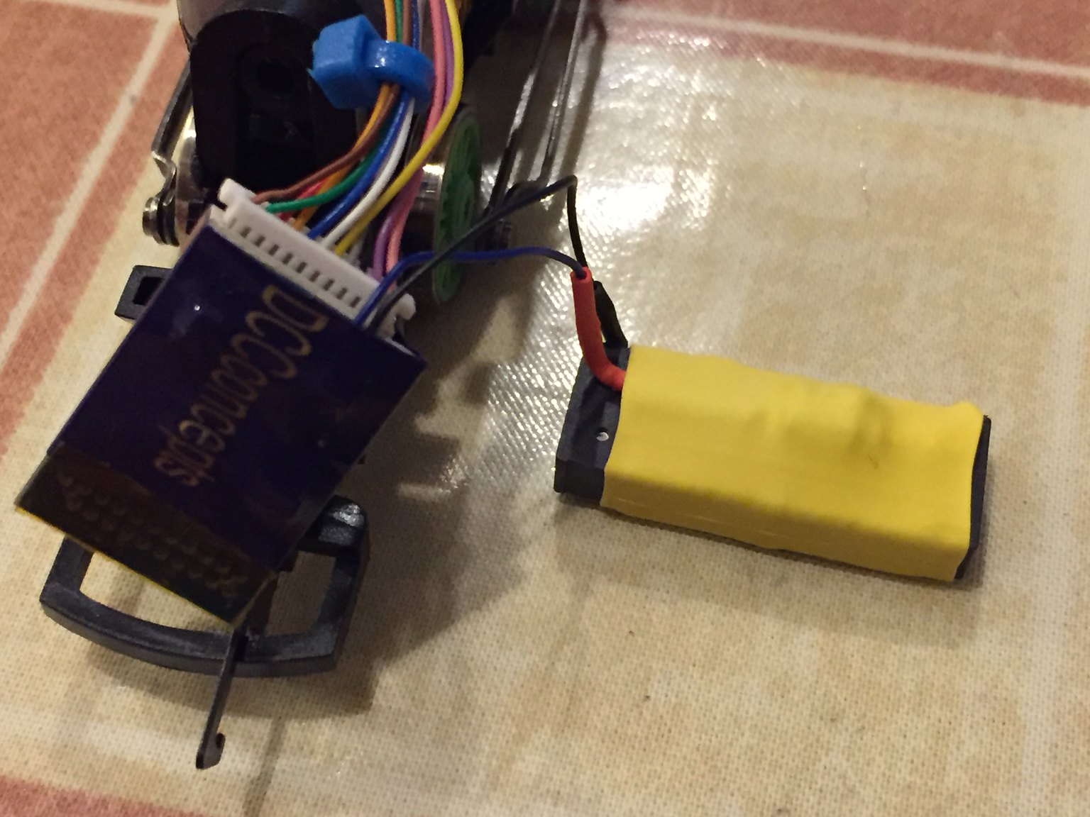
Video here (not sure if I can link a video - so here's the YouTube link: https://www.youtube-nocookie.com/embed/9hhorqaSWkI)So yes, the LaisDCC Decoder doesn't play nicely with my stay-alive.When the LaisDCC Decoder had earlier been fitted to the smaller of the two LaisDCC stay-alive units (860007), it did nothing.Connecting the larger 860009 unit certainly had an effect but on removal of track power - the loco's wheels (thankfully running on the rolling road) rand backwards at high speed.I'm coming to the conclusion that that particular decoder dosn't like any stay-alives! I guess it proves that you get what you pay for.Anyway ...The stay-alive with heat-shrink applied (makes sure there is no possibility for short circuits):
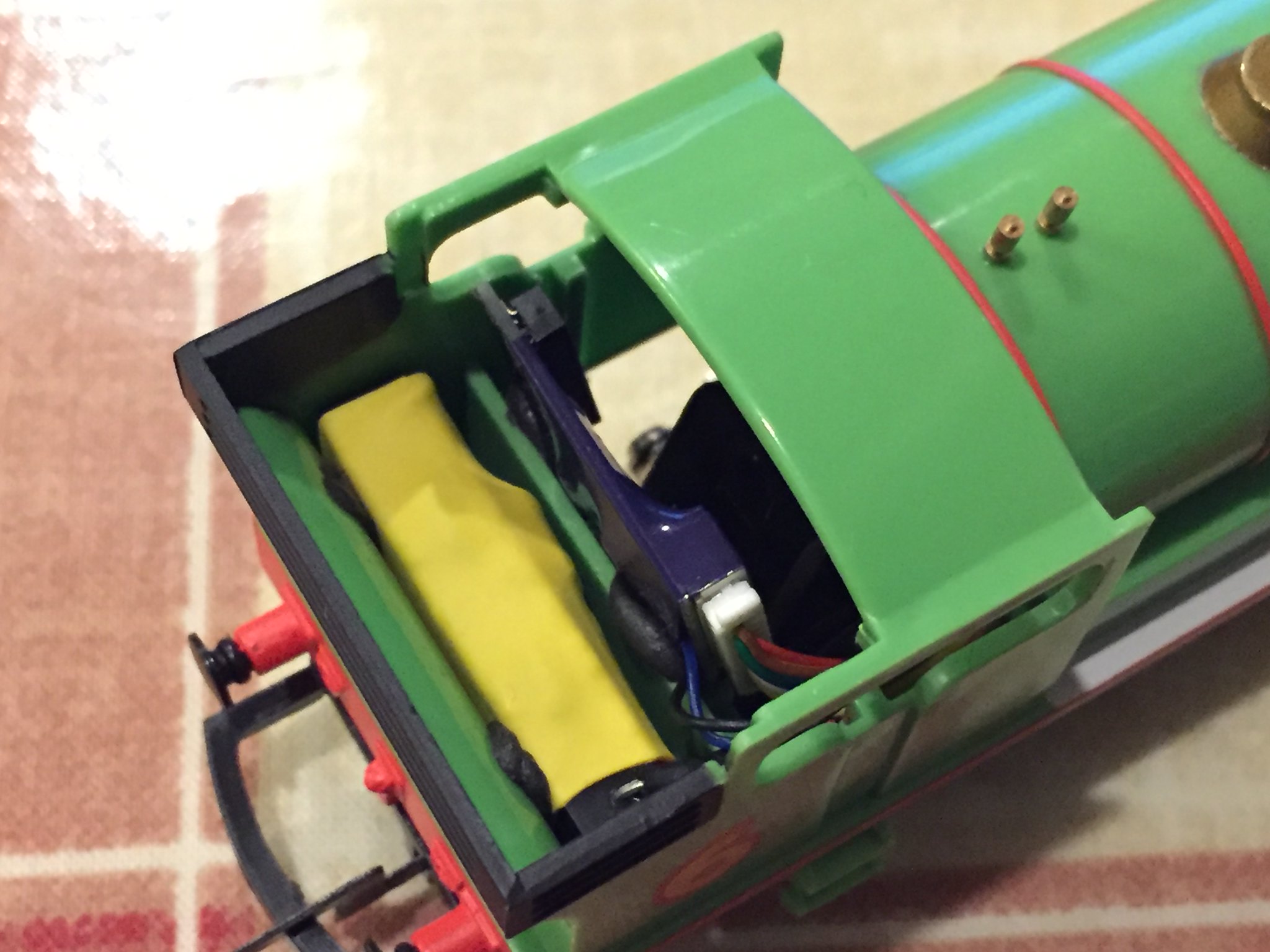
Decoder and stay-alive installed in Percy's bunker and cab and held in place by black-tack (really useful stuff that):
The positivesAs you can see, the stay-alive a) runs, b) runs in the right direction! c) lasts for around 1/4 to 1/3 sec (enough to get it over a dead frog)The one negativeOnly runs for around 1/4 to 1/3 sec and just a couple of cm.However, this is kind of what I was after. Possibly (if there is room) two of these could be wired in parallel thus doubling the run-time.Cost?Aside from the various different sizes of heat-shrink which I had anyway ...1x 1N4007 rectifying diode (1kV, 1A - although a 1N4001 which is 50V, 1A would do) - cost 8p (bag of 50 for less than £4)1x 100-ohm 1%, 1/4 watt metal film resistor - 1p?? No idea really as I bought a 'bag' of mixed resistors (10 of each of 30 different values for 99p)3x 47000uF super-capacitors at 40p eachSo, all-up around £1.30-ishBeats £3 for the LaisDCC 860007 (which did nothing) and £9 for the LaisDCC 860009 (which lasts for 25 seconds but runs in reverese and is way over the top).Plus, there was the fun of the journey as well
If you have managed to get this far, I hope you have enjoyed reading about this and maybe this will encourage you to try fabricating your own stay-alive units.Cheers,ArtHi can I ask what polarity should the cap be fitted to the DCC concepts blue and black wires? is the blue positive and the black negative?. Cheers T
-
Hi All, I've made a few different casts in the past for arched brick walls, flat and curved and I'm about to make a cast for a London based layout, but the trouble with using plaster for the final product is the weight mainly. I was wondering if anyone out there has used some sort of 2 part resin? I have but it's very expensive. I need probably 10 or more meters of arches and plain brick walls. Is there anything other that plaster? I use mainly Gyprock cornice cement its hard and fast curing, but very heavy. I'll put some pics up of what I'm trying to replicate
-
Hi Still no joy with the z21 I have sent an email to Rocco finger crossed. here is my email
Hi Rocco,
2 problems with my z21Start I have had this unit for maybe 10 years some of my decoders are that old. I use Apple IOS. on my iphone sometimes the slider speed control works but the slider is not visible. the z21 will not read some decoders I have a few TCS T1 and it works fine on the z21 but in Programming on program track it will not read any CV's. it is not dirty wheels or track as I connect the loco directly to the program track with croc clip oto the red and black wires of the decoder. I have a few locos that behave erratically and I cannot reset them with the z21. The app reads in red letters ' CV address cannot be read" In the update app it says Firmware 1.33. Also version 1.3.4. (5549).
I have asked RMweb forum and Z21 facebook page but no answers. can you help please ?
kind regards Terence " -
17 minutes ago, AndrewC said:
One thing that John missed. After the reset remove the loco from the track for a couple of seconds to cycle the power to the decoder. many decoders won't complete the reset until after a power cycle. I've got a few ancient decoders like the T1 and some Digitrax DH121s that are still fine with Z21 and Digikeijs DR5000 but needed the factory reset after sitting dormant for a couple of years.
Hi and thanks. The reset won’t work when I press the set Cv button the app light goes green on both Z21 and App stays green for ages nothing happens. Tried it many times.
-
J in appreciate your help. (1) Oops my mistake I know it’s CV 1 and I Also know CV 3 is the default for new and reset decoders.
(2) It is plugged into a harness and it is the right way round as I said it does run reasonably well.
(3)It not possible to reset CV 8 as z22will not read the decoder. See screen shot of App.
Reseting the decoder is the problem.
-
Hi just a little niggling problem with my z21 start . I have been using it for a few years and only recently set it up again after two years in a box. I have a new Wlan maus working well (sort of its battery went flat and I had to re prog the language!) and the older red Multi Maus. all good and wifi no problem.
The issue is with a few of my programmed decoders will not respond on the z21 iPhone or the iPad it is the black updated app. I have a TCS T1 chip in the loco and it will not recognise the chip it will not read any CVs or reset. I have taken the locoe apart cleaned all the contacts running on DC backwards and forwards the lights work and it works well the problem is I connected directly to the program track with the manual programming option on the app and it will not read any CV's. I found the original CV3 address which is 1 as it's logo number is 60001. I added it to my vehicles with the correct CV3 being number one and it runs fine backwards forwards except that I cannot reprogram the lights as they are not doing what they should.
I'm in CV programming> Manual> prog track. Annoying as I have a few like that and I'm far too stingy to throw them out. Also it's not a dirty track problem as I connect the track to the red and black leads with short croc clip cables that are soldered to the pick ups while the loco is on the prog track.
Any ideas or suggestions welcome. Cheers in advance


 I found this postcard on the back it's written 0-6-0 No L30. at Olympia. I hope this helps


")


Zimo ADAPLU
in DCC Help & Questions
Posted
Thanks for your reply I came to the same conclusion re adding a 2K resistor in series with the decoder + Blue wire. Thanks for the heads up on LAIS products I've now done some research on them.