

Godders
-
Posts
280 -
Joined
-
Last visited
Content Type
Profiles
Forums
Blogs
Gallery
Events
Exhibition Layout Details
Store
Posts posted by Godders
-
-
I tried these years ago and have never looked back.
Watch the video and then visit website to see variations: -
24 hours later, the problem had cleared and all is back to normal viewing in Chrome.
Haven't reinstalled AdBlocker yet.Godders
-
The RMWeb "Ad-blocking software/plug-in detected." is blocking my access to RMWeb, via Google Chrome, despite having :
A) Disabled my adblockers and
B) Removing my adblockers completely.
However, as you can see, RMWeb works perfectly OK in Firefox.
Any suggestions, as I can't get into the Chrome version of RMWeb as I am logged in automatically.Cheers Godders

-
Hi James
I happened to be repairing my 56 and came across your article.
I drew a circuit diagram, I hope it helps.
I would like to know how the buffers are held in position. All 4 of mine have fallen out.Godders
-
Yes, Mick,
I have indeed noticed that over the years. The main problem, as with everything on RMWeb and elsewhere, is finding what you want, when you want it.
Nevertheless all very interesting and helpful. One can spend hours perusing.
Godders
-
Thank you both very much for the information.
Micknich, I have already being looking through many of your diagrams but I didn't spot this one, very helpful, I like diagrams.Thanks
Godders
-
Hello Folks
I hope it is permissible to re-open this subject.
I am going to design an interlocking frame for my layout. I have searched and not found a definitive answer to my problem.
The question is this; On a turnout with a FPL, is there interlocking on the frame as well as on the points themselves.Cheers
Godders
-
Hi Andy,
There is a problem with your solution; if Wayne does it commercially it will be restricted to the curvature he chooses. Unlike the present system purchasers will not be able to curve it to their own requirements, thus taking away one of the advantage of a kit.
Wayne the turnouts you have produced with the cast frogs are excellent and I believe the rail built ones will be also.
Cheers
Godders
-
 2
2
-
-
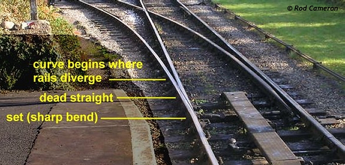
3 hours ago, martin_wynne said:
Hi Godders,
If you are getting your information from West of the Severn, I think you should know that the "set" bend in the turnout-side stock rail, which is regarded as optional East of the Severn, is regarded as essential West of the Severn.
")
It will significantly improve the gauging through the switch, and the fit of the switch blades. It is probably essential if curving the turnout. The position of the "set" is marked on the Templot templates.

cheers,
Martin.
Hi Martin,
How could you ever doubt that I would put a set in the rail.
However, my commission was to build the turnout kit, following the instructions, which I have done.
You may have noticed my comments about not gluing the Vee or soldering the electrical connexions. This is because I wanted to explore other paths after the initial assembly.
Oh ye of little faith
cheers
Godders
-
 1
1
-
-
Hi Wayne,
I forgot to ask, when will the 00-SF be on general release, I need several.
Cheers
Godders
-
24 minutes ago, Wayne Kinney said:
Thanks Godders for taking the time to build and review the kit!
Yeah, the switch blade pin hitting the webbing of the base is my fault, I forgot to move the webbing 'outwards' to give clearance, like I have with the EM and 00 Gauge kits. I've already amended this for production, thanks for spotting the error!
Nice to see you wish to try curving the turnout, I would love to see your results. I just did a small test and posted pictures of this on the other thread here.
Thanks again for your time!
Hi Wayne,
It was an absolute pleasure, your design is excellent. I have just corrected the Check Rail End Gap, following Martin's advice. Even the correction was easy, because of your construction method.
That's the beauty of having we peasants building the test kits, we are doing it to see if it can be built by the less skilled as opposed to experts.
However, having now built one, I feel I have become an expert. (Yeh, right)
I shall attempt to build a curved version, after absorbing the advice handed out by certain people, who are located West of the Severn. However it won't be today, the stress would be too much for a sensitive person such as myself.
Again Wayne I wish you the best of everything and hope Good Fortune smiles on you.
cheers
Godders
PS I was really impressed by the strength, alignment and look, of your chairs. It made threading rail so easy.
-
1
-
 1
1
-
-
1 hour ago, martin_wynne said:
Hi Godders,
Looking good, but that 2.08mm end gap dimension is for Peco track. It's a bit excessive for finescale track and does rather look it in your photos. Here are the default flangeway end-gaps in Templot:
00-SF: 1.58mm
00-D0GAI: 1.78mm (Wayne's Standard 00)
00-BF: 1.88mm
00/H0: 2.08mm (Peco)
EM: 1.58mm
When bending the check rail flares in these kits, I suggest matching them to the flares on the wing rails in the crossing casting.
The above dimensions make the same flare angle as the prototype flare angle (end gap = 1.3/4" greater than the flangeway).
cheers,
Martin.
Hi Martin,
you were perfectly correct. Thank you I have corrected the actual check rails (very easy with this kit) and amended my post.
cheers
Godders
-
1
-
-
Late on Saturday morning the postman handed me a largish box.
I was excited to get it and took it through to my desk for examination.
I have been waiting, with baited breath for the 00-SF version.
I believe that I was the last (lucky) person to be given a test kit of the:
§ B7 left hand standard turnout kit, OO-SF with code 75 Bullhead rail.
The parts of the kit are clearly displayed in the packaging.
I opened the kit package and duly read the instructions, several times.
Only then did I arrange the pieces, for photographing, on my desk.
I will list them as per the instruction leaflet:
· Turnout Base
· Cast Crossing ‘V’ (frog)
· Code 75 rail
o 2 stock rails
o 2 switch blades
o 1 rail, for cutting to form:
§ 2 check rails and
§ 2 heel rails
· 1 Tie Bar
I displayed the pdf of the turnout, on my PC.
https://www.britishfinescale.com/v/vspfiles/pdftemplates/00/Standard/B7/00_B7_TEMPLATE_A3.pdf
I also displayed a Templot template of a 00-SF B7 left hand turnout.
I measured the lengths of the check rails and duly cut 2 to 52mm, the rest of that rail I cut into 2 parts, to form the Heel Rails
At this stage I then prepared every rail end by cutting with Xuron cutters and filing square with a 6 inch file and slightly tapering the bottom flanges. Everything was deburred. This is to help the rails pass through the chairs.
I threaded every rail, one by one, into it’s final position, to be sure there were no, “tight spots”, there weren’t.
I found cutting the switch rails to length a bit tedious, but I wanted to get it just right and this required a little bit of trial and error because it also needs the Tie Bar to be in place.
The Tie Bar itself caused me a little confusion. I was not initially aware that:
a. It has a top and a bottom. The top is distinguished by a chamfered section.
b. It has tiny holes to accept the pins dropping from the switch rails.
In addition to this one of the pins was too long and interfered with the sliding action, not allowing full movement of the Tie Bar/Switch Rails.
This was easily cured by filing down the offending pin.
I assembled the whole turnout and tested with 3 randomly picked wagons and it worked beautifully, literally as smooth as silk.
At this point I realised I had not bent the check rail ends and it is not absolutely necessary for good running, as the chairs guide each end of the check rail, in a gentle arc.
However, I got the flare length, from the Templot template:
The Flare Length is 12mm and the End Gap is 1.58mm.
Even with the flares the check rails easily slide into position.
Please note at this point in time that I have not made any electrical connections, nor have I glued the “V” in place.
The reason for this is that I want, with Wayne’s permission, to see if I can curve the turnout so that the Turnout Road radius is 30 inches, my minimum radius.
I must say I am absolutely delighted with the kit. It is easily built and produces an incredibly strong, realistic looking turnout.
I have wondered for years why nobody has made a kit like this and my hat goes off to Wayne for so doing. He deserves every plaudit and hopefully lot’s of profit for his effort
Please forgive the quality and distribution of the photos. I've never uploaded photos before.
-
12
-
 1
1
-
 1
1
-
-
Thank you,
Best of luck, hope everything goes well for you.
Godders
-
2
-
1
-
-
Hi Wayne, thanks for the heads up. When should orders be placed.
cheers Godders
-
Hi njee20
This is not an argument, it is a discussion. I have no intention of upsetting anyone.
I don't know Wayne only studied his products, past and present.
My hope is that his products will work fine and by what he has produced so far, I think they will.
If I was still working in the petrochem industry, I would be asking many more rigorous questions.However this is a hobby and this guy is trying to produce much needed products at very acceptable prices. I want him to continue and be successful and I don't think this is the time to question certain aspects of what he is doing.
All the best
Godders
PS I also live in (West) Sussex
-
2
-
1
-
-
"Wayne's not used 3D printing before in N gauge though, and he's said it's a blend of multiple resins he's using, so I'd not fancy the chances at being able to say with any real conviction. Again though, I wouldn't foresee it being an issue. Painting it may be a good idea, as that'll stop UV related degredation. Unpainted in a garden may be the biggest issue - a lot of 3D resins go brittle under continued UV exposure."
Painting may well slow down UV related degradation but if you don't know what the material is, how can you possibly apply the appropriate paint finish to it. Painting it may be the worst thing you can do.
"All of those other suppliers are using injection moulding, which is a known quantity. It's a perfectly valid concern, given people may well expect track to last decades."
They may well be using injection moulding but it is not a known quantity, it varies in quality very much.
"When plastics first came on the market life expectancy had never been thought as an issue, some plastics last longer than others. Now we know more I think it is a good question "
It may well be a "good" question but given the above statements, how is he supposed to give a "good" answer.
-
2
-
-
I would have thought the question of life expectancy, would be known to, "FinetraX", as they have been manufacturing for many years, in N gauge. In addition the supplier of the plastic for printing will probably, also have a predicted or actual life expectancy.
Do people always ask this question, as I don't remember anyone asking the life expectancy of; Peco, Hornby, Bachmann, Dapol, Accurascale or any other of the myriads of suppliers.Indeed, does anyone ask how long their house is going to stand or their car going to last.
-
6
-
1
-
-
Hi Wayne, most of the people, who have taken the 16.2mm route, have done so because of Templot. We want to have a consistent system, please don’t ruin your product by diverting from a well trodden route.
Cheers
Godders
-
4
-
1
-
-
20 hours ago, Wayne Kinney said:
Yes, templates will be available on the website once the kits are released.
Hi Wayne, I thought, as you were creating as a B7 the templates would be available by using Templot or am I missing something.
BTW best of luck and congratulations. I have been wondering for a long time why you hadn't done this.Cheers
Godders
-
1
-
-
I haven't actually touched one of these but from what I can see, on the Fleischmann site, they are wired as follows;
There are 3 connections, Black, light Brown and dark Brown.
The Black wire is common, the other 2 change the direction of the solenoid.
I have not discovered which direction is which but it is easy to tell.
Connect the Black wire to one leg of your power supply, which should be an ac supply between 12 and 14 Volts.to test it touch the other leg of the power supply, momentarily, to one of the Brown wires, observe the way the point moves, if at all, then
do the same to the other brown wire and it should change the other way.You have now determined the direction of travel.
Write it down and tell us, so other people may know which connection is which.Cheers Godders
-
22 hours ago, dasatcopthorne said:
I've built a whole new layout using the new Bullhead track and I think it is great stuff and until recently I've given it great reviews and encouraged others the use it.
BUT.
I built it on the understanding that the Double Slip was due last Autumn.
Now my layout has a temporary Flatbottom Slip in place that I can't ballast or paint as it will need to be sold to finance the Bullhead one.
People now always ask why it's like that and the situation just puts them off.
I know Peco were making PPE stuff but that came in March/April. A long time after their website piece dated Aug 2019.
Dave.
Carshalton & Sutton MRC
Hi Dave,
I was surprised, nay shocked, that you were using Peco BH.
You were my role model for 4-SF, I thought you would have just, "knocked up", a Double Slip in 4-SF. HahahaRegards Godders (The fat guy from Three Bridges)
-
1
-
-
3 hours ago, DavidCBroad said:
I use micro switches on DC but only outside, point blade contact has been fine inside for the last 35 years or so. DCC point blade contact doesn't last long so you probably need relays to cope with the power. My micro switches are only rated at 1 amp the same as my controller.
Hi David,
your statement is puzzling. If I read you correctly, you are saying a dcc loco uses more power than a dc loco and therefore needs micro switches. However, you only use 1A ratings. Please explain.
My friend, who has a large US layout, uses the switch blades only, to my disdain, and has done for 20 years of dcc operation, without problems. The layout is 30ft x 10ft and only has about 6 feeds. It was converted from dc to dcc by simply changing the controller.
Thank you
Godders
-
1
-
-
Thank you Tim and Hayfield,
I had not realised that the pcb is effectively taking the place of the base of the chair.
Now it all makes sense, excellent.
Thanks
Godders
-
2
-


")


Attaching two floating shelves together to use as a baseboard
in Modelling Questions, Help and Tips
Posted
The rebate is only 1.6mm and it is square: