


Scorpio7uk
-
Posts
73 -
Joined
-
Last visited
Content Type
Profiles
Forums
Blogs
Gallery
Events
Exhibition Layout Details
Store
Posts posted by Scorpio7uk
-
-
3 hours ago, JeffP said:
I recently wanted drawings of a BR Britannia,
If you are still looking for it, there's a fairly decent GA of the elevation and plan of the Britannia in 'A pictorial record of British Railways Standard Steam Locomotives' - Edward Talbot 1982/2000.
Worth getting for any BR standard in my opinion, there's a few other GA drawings in there too.
NRM is the place to get the full size versions.
Jeff
-
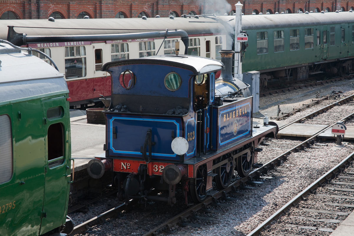
19 hours ago, nickd said:
Can anyone tell me whether there's a gap between the tank top and boiler clothing or does the boiler clothing sit on top of the tank top?
This may help Nick - https://docbrown.info/docspics/ArchiveSteam/loco31178.htm
The backhead shot halfway down seems to show that the gap is filled - whether it was like that before preservation - I don't know.
http://www.bluebell-railway.co.uk/bluebell/pic2/wn-2012b/323_johns_29may12h.jpg
Hard to tell from this shot but it may be useful to you anyway.....
Good luck!
Jeff
-
Good News!
Had a chat with Richard Webster on the Dapol stand at Kettering yesterday - they realise the error of their ways and will be retooling the underframe so that it has the correct W-irons!
Makes life a lot easier for us who want something to be right - I didn't ask about the axleboxes though - presumably these are separate items and easy for them use ones from their 'stock' that they've already tooled?
Jeff
-
 2
2
-
 2
2
-
 1
1
-
-
55 minutes ago, Hal Nail said:
The standard Dapol underframe design is a cast block which screws to the body, with plastic side frames/axleguards which just slot in place. Brakes cylinder etc glued into holes in the metal base. There is a rocking beam built into one sidepiece to give compensation.
Very useful - thanks, I should be able to work with that......
Jeff
-
....I have a cunning plan...... or at least I think I may have.....
If the chassis unscrews from the body (as it seems to) then I can replace the underframe fairly easily with correct bits and make some BR standard wagons that are suitable for the underframe - have to have a close look at them before I buy.
Do they have an unpainted option I wonder?
Jeff
-
18 hours ago, Aire Head said:
The target audience for these is probably people who don't want to kit build and either don't know or don't care about such details.
The LMS vans were available from Freightman and crop up quite often on the like ls of eBay and even offer a bit of variety with different ends and sides being available.
Here is a couple of mine to show how they scrub up

They look really nice.
I know about about the Freightman kits but I haven't been able to get one on ebay (yet) - I need 4 ideally.
If only I wanted them when they were available!
Jeff
-
Deleted
-
I don't get this - for the GWR vans at least - why produce something that is less accurate than the easy to make kits that are readily available?
If you're going to have to hack about with the underframe to make it right, you may as well just make the kit - it'll be easier!
I was looking forward to the LMS vans as these aren't available as kits - I think I'm going to have remove the chassis entirely and replace with some etched bits - or see if I can just get the raw bodies from Dapol (unlikely I know).
Jeff
-
I've managed to get the figures below from 'GWR Goods wagons' Atkins, Beard, Tourrett - I think I've added them up right!
Those possible from the Peco kit (last 22 of V4, V12,V13, V14,V16,V18) - 10,881 - all 9' wheelbase - 16' length.
I believe Peco sell packs of buffers, sliding vents etc to do the variations.
(V21,V33) - 1,886 - all 9' wheelbase - 17' 6" length.
V33 - Parkside/Peco
(V23,V24,V26,V34,V36,V37,V38,V39) - 8,267 - all 10' wheelbase - 17' 6" length.
V23/24/26/36/37 - Parkside/Peco
These were all the 'standard' vans - there were early diagrams of various heights (V4, V5) - and of course the 'iron mink' (V6) of which there were 4,901.
There were also shock absorbing vans (V27,V28) and V35 which was the standard SR design.
The 10' wheelbase vans were built from the end of 1933 and the last diagrams were built by BR - BR withdrew the remaining 9' wheelbase vans from about 1956.
Hope this is useful.
Jeff
-
1
-
4
-
-
23 minutes ago, Mikkel said:
If you look closely at the front end of the first coach you can see "GWR" in he waist panel above the lefthand "supporter" of the garter, which should make it 1908-12 all "brown".
Well spotted! I wasn't sure of the differences - I thought it was lining that was different.....
If the GWR used its best and newest stock on the 'Cornish Riviera' then it's more likely this is 1911 then with all Brown coaches. I don't think there's much chance of figuring out the liveries on the other coaches.
Jeff
-
4
-
-
1 minute ago, Compound2632 said:
So its reasonable to assume that it is in the livery it first left the Swindon paint shop wearing.
Yes - which means it's either Brown or Lake - depending on which batch the coach was!
I believe there's small differences in lining etc between the two liveries but impossible to tell on photos such as this.
Jeff
-
3
-
-
The first coach looks closest to a D51 www.gwrcoaches.org.uk - look under Churchward coaches - Toplight Bars II - built 1911 & 12.
The dreadnaught diner was built a lot earlier - circa 1904 - but still the best the GWR had at the time.
Jeff
-
2
-
2
-
-
it appears that North Star has a long cone boiler - according to RCTS, this was fitted January 1911 (presumably with the top feed) and as previously stated, it was renumbered 4000 December 1912.
So the picture can be any time between 01/11 and 12/12 - as to whether the coaches are Crimson Lake or Brown - the livery changed to Lake in 1912 - not sure when in 1912 though - anybody know?
I don't think there would be a mixture of liveries - the 'Cornish Riviera' was the GWR flagship express - this is a commercial company - image is everything, so it would use only the best, most modern image stock it had available - so I don't think it would be a mixture - either Brown or Lake - though I'm happy to be proved wrong!
Jeff
-
2
-
-
19 hours ago, Miss Prism said:
Steam Railmotors and Buffalo tanks. The one in the picture is inside framed, and looks big wheeled to me, so isn't a 2021. Apparently a few 655 and 1501 locos were autofitted. The other possibility is that the train in the film isn't an autotrain, but is a down service that has quickly parked itself on the up line to make way for the down express, prior to running round. That would be a bit odd though - difficult to imagine Laira running out of autofitted tanks.
Not a 655 or 1501 - definitely an 850 or 2021 - you can tell as the top edge of the buffer beam is above the footplate - only the 850 or 2021 is like that.
Jeff
-
3
-
1
-
-
If you haven't done already, I would try contacting the Welsh Railways Research Circle ( www.wrrc.org.uk ) - they have already published two books containing the drawings of Jones & Lloyd, so they have permission for those drawings - but the copyright for the articles may still be with whoever published MRC (if they still exist).
Sorry if you've already gone through these channels - just thought I'd make sure.
Thanks
Jeff
-
 1
1
-
-
Can I just check - what scale is this?
Jeff
-
Yes - I've sent you a message with a pdf version of the instructions.
Thanks
Jeff
-
1
-
-
I think I've solved the brake hanger issue:-
The are two different brake arrangements, the early version which is what you were aiming for:-
(the pictures could be clearer - but they show what they need to).
...and the later version with the brake compensator..
The driving wheel brake hanger is always the same but there are two different lengths of hanger for the trailing wheels - the longer one should be used for the earlier system and shorter one with the brake compensator added should be used for the later system.
Left is the short trailing hanger with compensator for the later system
Middle is the earlier long trailing hanger for the earlier system
Right is the leading hanger for the driving wheels
I think what you've done is used the later, short hanger without the compensater instead of the longer one.
The parts are identified on the etching layout sheet, though some of the leader lines could be clearer - I'll try to clean it up a bit.
At the end of the day, you've got round it and made it look right - I didn't even notice any issue on the pictures of the first one.
Thanks
Jeff
-
1
-
-
No - translating weird shapes into flat is never easy, even on CAD.
I believe that a lot of plotting was involved with a circle representing the round boiler with lines drawn every millimetre or so to get points on the flat - then you 'join-the-dots' with the best fit curve - I think you would use the same technique on CAD, but with different tools.
I will look into the brake block hanger issue you mentioned - it's weird that it should get through after all this time.
Jeff
-
Splendid work again Nick - I'm glad it went together well (mostly) - not bad for a 21 year old hand-drawn artwork!
Some of the colours have faded a bit over the years but it hasn't done too badly.
If you're wondering what the gap is - it's where panel on the right will be 'mirrored' by the etchers.
It's drawn 2:1 to improve accuracy and mounted on thick cardboard - the tags are done by Tip-ex.
Some of the early chassis stages were drawn by me, but the rest was done by Dad, Patrick Ennis.
It was the first 'early' engine we designed - all the previous kits were firmly Churchward and later and designed by my late Brother David.
I'll leave you to guess what the drawing on the wall behind is......
Thanks
Jeff
-
4
-
 1
1
-
-
Let's face it though - a badly designed kit is still a badly designed kit, whether hand drawn or CAD - it's just that with CAD - it's wrong to two decimal places!
We used to draw artworks at 2x scale to minimise error as I'm sure a lot of others did - CAD has improved things a lot but I still miss cutting out all the parts and sticking them on large mounting boards and making all the tags with tipp-ex!
I don't miss spending ages painting in large blocks of red around tiny white half etch rivets though - this now takes a few seconds on CAD.
Jeff
Scorpio Models
-
6
-
3
-
1
-
-
...only 4mm too narrow? Must have been one of Gateneal's good days!
You've done a good job as usual - you would never know what you started with.
I've got a pile of Gateneal kits to make/bin sometime - brought them 30 years ago before I knew what I was doing - I'll have a look at them some day!
Jeff
-
Looks good but isn't that DC03? I thought DC01 was the one with the swan neck and the handles one end of the wagon?
Jeff
-
I know this is a very old post but I'd just like to confirm that they were done in 7mm.
Me and my Dad purchased enough etches to do 9 coaches of the following diagrams C24x2, D42x2, E77x2 & H8 (all Dreadnought) - K22 steel toplight full brake and a F13 Concertina 70' slip!
They are dated 1980 and I think we brought them in around 1991 - I think they may have been from Westdale - not sure.
Don't know who's got the tooling now........
I was looking at them as I'm considering doing some GWR coach kits to a high standard with full underfame and interior detail (I've been inspired by the MMP / David Parkins range).
I thought I'd start off by doing an underframe kit to suit the Dreadnoughts above (just for my own use) to prove the concept which is why I dug out the etches and started searching to see if anybody's made any models on RMweb - haven't found much so far....
Jeff
Scorpio Models
-
 1
1
-


Producing brass casting patterns
in Kitbuilding & Scratchbuilding
Posted
I would also add that quite a lot of pressure is involved in vulcanising as well so do not make your masters out of anything brittle and you would be best to arrange the part in the mould so that it can take the pressure - 'flat' rather than 'end on'.
Jeff