


Wherry Lines
-
Posts
527 -
Joined
-
Last visited
Content Type
Profiles
Forums
Blogs
Gallery
Events
Exhibition Layout Details
Store
Posts posted by Wherry Lines
-
-
Whilst I am very happy to see they've finally arrived, I wish they'd spaced the releases out a bit more!
-
I've now run in my EMT example for the full hour and I am rather impressed by the quality of running. On DC, it is incredibly smooth and quiet - and that's on a 40 year old homemade controller! There is a nice weight and a solid feeling to the model and livery application is superb. Coupling the two coaches together is easy, but a little care must be taken to avoid bending the 4 connection pins.

I thought I'd try out coupling compatibility with the Dapol 156. Whilst the couplings look dimensionally very close, the Dapol coupler is very slightly chunkier, so will not engage with the Farish 158. Not surprising, but a bit of a shame as they look good together.
-
 4
4
-
-
Quick comparison photo between an original tooling Bachfar release and the new tooling.
-
5
-
 1
1
-
-
For me, the original plan with 3 points looks much better. It appears to flow far more nicely.
There is an Ian Futers variation of Victoria Park for freight only too:
-
7
-
-
Excellent work James - and a little project which no doubt brought great pleasure!
-
 1
1
-
-
Actually build a layout!
-
1
-
2
-
-
I would be inclined to model the maintainence shed in low relief, with more of the trackwork in the open. It would open up the layout a little and make it seem a bit larger. You could always have the doors open with a cut down wagon in each doorway too.
-
1
-
-
Thanks for your thorughts @Chimer.
Funnily enough, I'd had the same thoughts as you on the extension! The station itself was located on the other side of the crossing to the location I am modelling (to the left of the modelled area on my proposal). The line then continued onto Great Ryburgh and Fakenham. A small 'fiddle-stick' long enough for a cl.101 would suffice.
I have also come across a couple of photos showing a buffer stop on a short length of disconnected line - perhaps a headshunt. I could reconnect this in place of the kickback. It would be long enough for a couple of OBA wagons.
I've doodled over a screenshot from Google Earth to show the location today - it's part of the Mid-Norfolk railway, although not used for passenger services yet.
-
I was about to suggest Futer's Victoria Park concept, but AndyB has beaten me to it. Probably an ideal track plan for the space.
-
1
-
-
Afternoon all,
A few failed attempts at layout building over the past 15 years and a break have led me back here again - planning an achievable but interesting layout! Previous attempts have probably been too complex for a first time layout, so something simpler is called for.
Living on the Norfolk/Suffolk border means that I'm interested primarily in the G.E territory, particularly the late 80's and 90's when I was growing up. Trips to Norwich on a 101 or 150 being amongst my earliest memories.
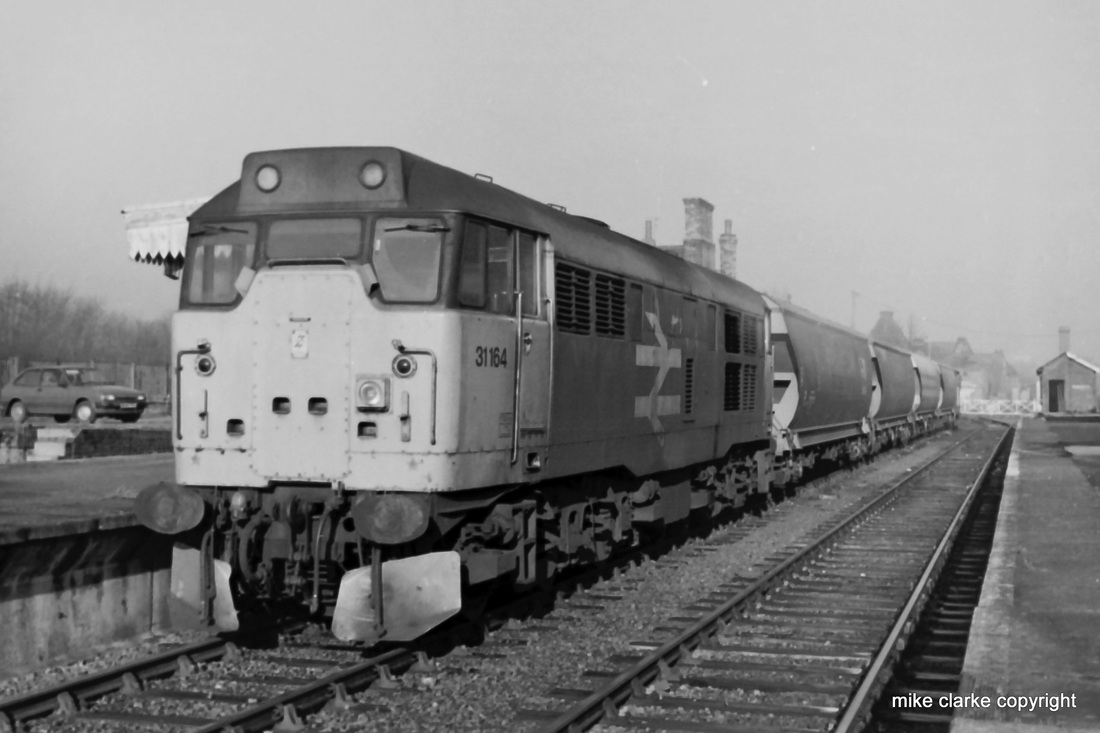
So, naturally my layout is based in this locale and time frame. I've come across some photos of North Elmham, north of Dereham on the Mid-Norfolk. There was a grain facility at this point, located on the opposite side of the station itself. A fairly simple track plan, short trains and easily modellable. The prototype closed in 1989.
https://www.flickr.com/photos/mike_clarke_railway_photos/6280419985/
https://mikeclarkerailwayphotos.weebly.com/uploads/8/1/4/2/8142320/6010729_orig.jpg
A couple of polybulks, a guards van and a class 31 are all that are needed, so I would use some artistic license to increase the traffic and traction for interest. A couple of VGA's, open wagons, maybe a small engineering train with typical East Anglian traction.
I've kept closely to the track plan, but added a small kickback siding off the grain siding for extra opeeational interest. Unusually, I've lengthened the track plan a little compared to the prototype! Dimensions for the model are 4' x 1' for the modellered area, plus 2' for a fiddle yard.
Here's the intended plan using actual track, a class 37 and 3 monsterboxes (my polybulks are up in the loft! The level crossing would be on the left as viewed, with gates closed to divert the eye from the solid backscene. Fiddle yard is to the right, disguised by a bridge carrying Hoe Lane (conveniently moved much closer to the location modelled!
What do we think?
-
5
-
-
Look for a gold rated 'Sold Secure' lock. Something like the Abus Granit X-Plus 540 or Kryptonite Fahgettaboudit D-locks. Use in co junction is a shackle lock to secure the wheels and frame together too. Kryptonite make a gold-rated one.
-
 1
1
-
-
I see that the Pacers aren't mentioned. I think I made my pre-order for one back in 2013!
-
Using my local area as an example, Greater Anglia have been using an East Midlands 158 on the first Norwich - Lowestoft & return weekday service. In the past couple of years, I have also seen an Arriva Wales 150 in use and a London Midland 153 as well.
-
Good evening all.
I must admit it's been a while since I've wired up a layout and I may be a little rusty in parts, but I thought I knew how to wire up a fairly straight-forward layout (such as Minories).
However, I didn't realise that Peco now produce their code 55 paintwork with the 'unifrog' (discussed here: http://www.rmweb.co.uk/community/index.php?/topic/121872-unifrog/). I've read the leaflet that comes with the points, as well as the unifrog thread (several times) and I'm still somewhat confused.
Previously, I would've used insulated joiners to separate the two sides of a crossover, such as with this example from the entry throat to a Minories layout. But, I've read conflicting information on whether they're needed with the unifrog points.
So, do I need insulated or metal joiners for a crossover like this? I would want to use a live frog with polarity changing to improve running quality and would use a point motor which allows for this.
If I need insulated joiners, where else would they be required on pointwork? (I'm ignoring isolating sections as I know where I'm placing them!)
Many thanks for your guidance in advance.
-
First of all, it would be useful to know what the baseboard size(s) would be. But looking at the plan, I think you've tried to put too much track onto the boards. I think a 'less is more' approach would be better, especially in N-gauge.
Secondly, the track gets very close to the edge of the board in places.
-
1
-
-
You might be interested in this firm that make resin buildings.
https://www.facebook.com/pg/ALSACAST/notes/?ref=page_internal
Thanks to Nick for alerting me to the range of resin buildings made by Alsacast, I have now ordered their kit of the VAM 'overlaadstation' found at Harlingen. I've also thought about the name of the layout. Originally, it was to be based around the Zandvoort area, but I'm now thinking of keeping it around the Harlingen area. There is a road very close to the site of the former VAM facility called 'Westerzeedijk' and I wondered about using the name Westerdijk. I'd like to use a dutch sounding name, whilst avoiding using real places.
I am unlikely to make much more progress on the layout until I have constructed the Alsacast kit, but I have printed out a full-size plan of the layout to get an idea of whether it's workable.

This is the right - side of the layout. The pair of green VAM wagons are on the siding where I plan to locate the loader building (where it can also act as a viewblocker for the hole in the backscene). The 2400 and short train have entered the layout and are on the loop.

This is the left end of the layout. I envisage the backscene containing some sort of goods building or rail-served warehouse which receives and send out freight using vans. The other two sidings are most likely to going to be spare spurs for holding various wagons and the like.
-
1
-
-
If you can emulate the success of Nick's layout.
Thanks for the words of encouragement. I'll be pleased with myself if my end result is half as good at Nick's.
Nick, that website is a goldmine of useful information! It's not one I've come across, but certainly very useful for choosing suitable buildings.
-
Good evening all.
Well, a long time as past since my last post on here. A lot has happened in that time. I purchased my first home 3 years ago and have been busy renovating it. Naturally, this has severely impacted on modelling time.Whilst tidying up the other day, I came across a cardboard box containing my HO dutch stock and some hand-drawn track plans (which are also shown above in earlier posts).
I've been pondering over them recently and decided that I'm not keen on any of them. Cue much searching, looking at prototype track plans, plans in books and on here of course! I came across an interesting plan by Iain Rice on Google (an extract of a book with a 3d plan). I wondered whether Nick (Doctor Quinn) used the same Rice plan for Industrivej?
I have created two versions of the plan, one with a 'double track' exit and another with a single exit to a fiddle yard. With the single track plan, any 'running around' would take place using the loop on the board, whereas on the double track plan, running round stock could be done on the layout, or using the fiddle yard. The main traffic on the layout would be VAM compost wagons, with some van traffic as an extra interest - possibly loading and unloading at a warehouse of some sort (modelled in low or half relief). The spur on the lower right of both plans would have an overhead loading building for the compost wagons and also form a good scenic break.
It's worth pointing out that the plans are for a 6' x 1' 6" scenic area.

-
...my "Hockey stick" design slides lengthways and exchanges a foot or so lengthways for a foot or so sideways, 1 sq ft for 6 sq ft....
Still waiting for the OPs track plan
This is an interesting variation that I haven't come across before - it might be a design I have to consider for myself!
-
The other location I'd really love to model is Norwich Thorpe
I would love to model this too, but it's about 12' long in n-gauge!
-
Something different. Class 91 drags in the north east.
April 1994. 47635 hauling 91019 past the site of Hart Station, north of Hartlepool.
This isn't 1994 as GNER didn't exist until 1996.
-
Here's the full video I took at beckenham
www.youtube.com/53oOF9MX24g
You need to press the 'link' button when inserting a URL:
-
I really enjoyed seeing Emsworth 'in the flesh' at Southwold.
-
I thoroughly enjoyed seeing Saltdean at Southwold. Such a fantastic piece of pre-grouping modelling. Lovely locos too!


Class 158 - New Tool
in Graham Farish
Posted
The Dapol and Farish BSI couplings don't work. I've tried already. Tiny dimensional difference!@