


PaulR
-
Posts
96 -
Joined
-
Last visited
Content Type
Profiles
Forums
Blogs
Gallery
Events
Exhibition Layout Details
Store
Posts posted by PaulR
-
-
On 12/09/2018 at 19:21, PenrithBeacon said:On 12/09/2018 at 16:08, Knuckles said:
Used a few drawings but mainly the Pochin one and about 30 photographs etc. Data from books and the internet were collected to make the conclusion, can't remember all of them.
I always gather as many drawings as I can before designing as it has proved to be a consistent issue that they hardly ever agree 100% with each other, the photographs or published dimensions...and even they don't always agree sadly.
The majority of the design was from the drawings and photographs.
It was designed in 4mm and has been re-scaled up and down since. Some walls and details have been thinned out in the larger scales to take advantage of the extra printing tolerances.
Any use?
------------------
Gresley A1/A3 Reduced Loading Gauge Cabs now available. Can be used with the SCC A0 range or for normal A1/3 projects. (4mm currently)
https://www.shapeways.com/product/XFGWWZYS8/a0-a1-a3-cab-reduced-loading-gauge
https://www.shapeways.com/product/M79XHL3AK/a0-a1-a3-cab-exp-reduced-loading-gauge
Not sure! Why didn't you consult with the Cumbrian Railways Association? The Pochin drawing have long since been discredited.
I have been a member of the CRA since 1983 and I can say the Pochin drawings are held in high regard. They are certainly not discredited. Where is PB's evidence for saying this?
-
True. It can get stressful at times and is a headache but I perceive it to be a necessary evil in areas. I'm just doing the best I can - can't please everyone but I try!
You could suggest to LRM to make just loco bodies and not offer a matching chassis for them, see what they say!

I think the difference between the ride height on the J1 with different driving wheels would be about 0.75mm but I haven't measured yet to be sure. This is also why I'm thinking it can be easily made to work with both wheel sizes providing the leading wheels are set up to have adjustment in height and the right amount of play - easily done with a washer.

LRM have been making their models for years and were not chatting about the difficulty of getting the correct dimensions for a chassis. I mentioned what I did as a possible method not the only one, precisely because I DID want a squared up chassis, it fitted and has the right dimensions ( to a mm anyway). I will now withdraw from the discussion and leave you to make your decisions
-
I'm all for people sourcing their own chassis and I honestly hope some do so to hopefully show versatility.
I have no doubt whatever loco bodies made will be able to fit RTR or other company chassis, in some cases with a little adding or taking material from either.
But to suggest I don't even bother making a chassis is ( with respect) a silly idea to be honest. I need to make one in planning to make sure things align and splashers clear
the wheels etc so to not finish it off and offer it as an option to those who may want it is a pointless loss.
I've already sold chassis' proving to me some want them. Also my E2 chassis has the correct wheelbase of 8' 0" equally spaced whereas the others you can get from others don't as the middle wheel is not central to the others. If it had splashers and another chassis kit from someone else had a different wheelbase it wouldn't fit.
So I make chassis' for each engine as an option and to be as complete as possible with what I currently am using, namely Shapeways. I do have designs on etches and doing things differently maybe one day too.
Also part of my aim is to ease people into loco kit building as I know many who are scared to. Having a fully squarely printed chassis already ready to accept your motor and gearbox is for some people a godsend. Logical and I have been told words to similar effect!
Again, by all means source alternative chassis but they are and will be there as an option.
I don't know, these are the same questions I ask! As we found with the Cambrian Conundrum different material says different things so investigation has to be made
Sure, my knowledge of the Cambrian is very thin so I would not presume to put forward an opinion there but I have been modelling the Furness for years so express a view with some confidence. I remeasured the Pochin drawing as it does not have dimensions on it and confirm it is the same as all the others I have quoted. Anyway, I should stop worrying about it and if you feel you must make a chassis, do it to either dimension; no one will worry about one mil (in 4mm scale) and you need to sleep at night without all this torture!
-
 1
1
-
-
Rather than keep counting the number of angels dancing on a pin, why not let the purchaser source their own chassis? I have a nickel silver model of the J1 built for me by a fellow EM member but I used the excellent London Road models LNWR 5' 6" 2-4-2T chassis
Another source, IA LIndsay, in MRN for Des 1964, shows E1 No 58 as having 5' 6 " driving and 6' 6" between pony and leading driver. Why on earth would the Furness change any of this when rebuilding a loco less than 20 years old?wheels
-
Ok, I'm not sure what your point is though. :/
I got mine from the link I put in.
Rather than keep counting the number of angels dancing on a pin, why not let the purchaser source their own chassis? I have a nickel silver model of the J1 built for me by a fellow EM member but I used the excellent London Road models LNWR 5' 6" 2-4-2T chassis
-
Could you please explain post 93? Pochi's drawing has the bigger wheels and 8' wheelbase too.
Both drawings scaled to the wheel sizes also gives the correct 3.5FT / 14mm rail top to buffer centre measurement which also makes me think it might be right.
What I'm doing isn't RTR true, but I'm trying to get things as close to it as realistically possible. It will be a bang load quicker to get an SCC model completed than a traditional loco' kit; not that I'm taking away from that as I really enjoy building an etched kit once in a while.
A future ambition? RTR Em and P4 and 00. All of them. Yeah ok sales in EM and P4 may not be amazing as most are doing 00 but that doesn't bother me too much - I just want to see it become a reality - it'd encourage people to try EM or P4 too I envision.
The Pochin drawing I have is from the HMRS magazine
-
Markits do some etched ones, but they are probably for specific locos to match their prototype wheel sets.
Can't you add them to the 3D print? I would add them to the artwork for an etched kit, so that the builder doesn't have to get them elsewhere.
Balance weights are easily made from a variety of materials. I would leave that to the purchaser, as they will not be put off by making their own; after all, this is not the rtr segment of the market.Back to the authorities: they come no better than W Hardin Osborne, Ross Pochin, and Rush all agreeing the dimensions in post93 and add in Gradon on the E1 wheel size as well.
-
Maybe I know what you mean. A gaping hole that you can swim around in is only 0.5mm thick or whatever. I set the snapping option to 0.1mm so it is quick and easy to adjust to that but if I want finer I just zoom in. Sometimes I need to adjust something to 1/40th of a mill' or something silly. Isn't that often though.
I checked the Alan Gibson catalogue and they do 3' 6" and 3' 7" wheels and 5' 6" wheels, also for the 5' 7.5" wheels they do 5'8" so they if accurate are only a pinch bigger.
I have noticed though that the 3' 0" bogey wheels I brought before measured at more like 11 or at a push 11.3 or so. I wasn't too impressed with finding this out.
I know the website says wheel sizes might be a wee out in areas and the excuse is used that real ones were - true, but I'd still like it to measure up as should. Never mind.
Actually do you know anywhere other than Ultrascale where you can buy various types of balance weights? I always struggle to find these and usually end up scratch building them from plastic card.
May I add my six pennorth? The J1 was indeed a rebuild of the E1 tender locos, originally made by Sharp Stewart of Manchester. All my authorities state that that the driving wheels were 5' 6" and ponies 3'6 ". It was 7', 9" betrween drivers and 6'6" between drivers and ponies. The rear ponies were placed in a bolt-on addition to the mainframes. One of them, I think number 47, retained its trumpet shaped safety valve cover, while all the others got Ramsbottom safety valves.There is a lot of external rivettingon the tank and bunker sides, as there was on the Neddies. When I had the latter 3D printed, I also had some half etched cab sides done in nickel silver to simulate this but I expect there are other means to do it. Hope this is helpful,
Paul R
-
1
-
-
I always do the chassis first, although you have to decide what gearbox and motor hou are using. The 00 prototype builds used the motor and gearbox in the instructions purely because I wanted something that wouldn't require me doing what many kits require; namely cutting into the firebox or boiler for extra room.
As to be expected it is under powered but did its job in proving to me (and the world via the vid) that it can be made into a working loco.
I actualy cut a wee bit of boiler on the K2 in order to bung in a flywheel and as a result I think I'll make it a personaly standard to do so. Visually it didn't detract as much as I thought it would.
The other reason I do the chassis first is because sometimes I find it useful to put the body on to test fit everything and it is better to do that to a body that hasn't been completed due to less handelling needed.
The insides of the splashers and the bottom of the body will likely need shaving a little to give room for the rods as the scale thickness of the real running plates cannot be achieved just by printing due to tolerances so a little shaving is needed post production. It's easy, just a small bummer.
For the splasher insides a sharp scalpel works nice and for the bottom of the body a few passes with a mini drill and wire brush make short work of this.
Hope that doesn't put anyone off, it's in the instructions anyway. I'd rather tell you all than you think it is carelessness. Rather than model the loco out of proportion and have things shaped odd or run too high I'd rather model it so it is accurate with a little fettling needed.
Does any of this help?
Do the coupling rode come with the chassis of the FR K2 or do you have to purchse the brass ones?
-
This is my 7mm Small Sharpie
would this be the same as you want in 4mm. Mine is from the Dragon Models kit.DonKnown by Furnes fans as a K1. I have the Dragon Models' version in 4mm scale
This is my 7mm Small Sharpie
would this be the same as you want in 4mm. Mine is from the Dragon Models kit.DonKnown by Furness fans as a K1. I have the Dragon Models' version in 4mm scale
-
Paul,
Have you got any more information?
I echo Siberian Snooper's advice. Coopercraft have not sent goods or refunds from their site for years. I have had to invoke the dispute system of my credit card to get a refund. Occasionally, he pops up at shows, so buy there
-
The Slater's kits are now with Coopercraft and some parts are available separately.
Forget about Coopercraft. There is a whole correspondence on them elsewhere on rmweb
-
 Ok it's ready, Cambrian Class 61 Locomotive and the chassis for sale.
I will aim to get the Phoenix superheater version. Will you be tweaking it soon?
-
Thanks, I appreciate that.
For WSF smoothing my current method is to use P600 wet 'n' dry paper to start with, rub it fairly firm but don't smooth down the detail such as boiler bands. Then give it a medium thickness blast of Halfords Plastic Filler Primer (yellow cap) and then go over it with the papers. Using a finer 1500 grit paper is good too.
I find wetting it turns the primer into a thin cream that fills the surface nicely, for hard to get areas sacrifice a small fine file and gum it up and use that too.
I do this 2 or 3 times then it is ready for painting. Sometimes the top coat of primer before painting is the Tamiya fine primer as it gives a different effect and I'm undecided what is best currently. Hope this helps.
I spray with Halford's Red Oxide Primer (for the Furness) and finish with Phoenix Precision. There is also a Halford's surface filling primer that might be good
-
I did a test upload for the 3D prints in 7mm and a class 28 mogul experiment body was about £80 or £90 in WSF and over £200 in FUD. I did the maths...when you get everything else it is cheaper than some 7mm kits but others it is comparable to. Again it comes down to how much work you want to do, as you don't have to build so much for some as you indeed have said it suits.
The K3 and K4 are two loco's I've been thinking about doing for a while so I may indeed do it, but with so many to choose from I don't know yet.
The Furness took the splashes off yeah, like yourself I'm unsure if the Cambrian did. It's good that they were removed though as it gives more modelling choice and if you have to not use them due to tight curves it won't be wrong.
Ah but if it ever gets in a magazine they may pick it apart as to be expected, then favour the other drawing dimensions. I've linked this thread and the S4 one in the instructions for potential buyers to mull over everything.
Thanks
Always encouraging to know.To everyone - I have re-opened for sale the K2 related stuff that was locked due to this research. If you disagree with my eventual conclusions I sincerely apologise but I can't bounce forever as we are going in circles. The Chassis have undergone a rename and the information inside is updated.
The New Cambrian Locomotive and chassis will be released as soon as Shapeways auto check system gives the green light.
This isn't anything to do with 'New Year' as I'm a true April fool and believe the true new year is more around that time, specifically Pesach/Pascha/Passover, and what we have is a replacement. But you can research it if it interests you.
So going by what we generally call the New year I now officially announce the release of the
Cambrian Railways Class 61
...just as soon as I get the last green tick. Look out for it.

Re the cheaper surface: I find that priming it before using emery board or tape helps even the surface and therefore means less preparatory work. Meanwhile, I want to say how impressed I am with your work and wish you every good fortune with future projects
-
1
-
-
Seen the cost of a 7mm kit recently?
I think you are right about the bogie wheels being 3' 6". The photos are undeniable and I have looked through my Furness ones. They also used the same size on the K3 and K4. Any chance of those being produced?
-
Lol, not quite the tough of a button, but I know what you mean. Up scaling to 7mm etc also behoves one to look at axle hole size, material thickness either to thicken or thin...but other than that it isn't too hard no. Buying one is another story due to cost though.
Yeah, I'm trying my hardest to nail this one down. I feel strongly that those two picture edits have helped things and I'll soon re-release everything as some items have been on lockdown because of it. Good news is the few who already brought the K2 and chassis don't have to worry, unless they want the bigger wheels in which case may I introduce you to Mr File.
If you are adamant that the conclusion is wrong here's your chance to prove me wrong (taking into account the WHOLE thread) before I go ahead and take action. It isn't about being right or wrong, rather establishing truth and I'll bend to a solid argument.
Seen the cost of a 7mm kit recently?
-
Lol, not quite the tough of a button, but I know what you mean. Up scaling to 7mm etc also behoves one to look at axle hole size, material thickness either to thicken or thin...but other than that it isn't too hard no. Buying one is another story due to cost though.
Yeah, I'm trying my hardest to nail this one down. I feel strongly that those two picture edits have helped things and I'll soon re-release everything as some items have been on lockdown because of it. Good news is the few who already brought the K2 and chassis don't have to worry, unless they want the bigger wheels in which case may I introduce you to Mr File.
If you are adamant that the conclusion is wrong here's your chance to prove me wrong (taking into account the WHOLE thread) before I go ahead and take action. It isn't about being right or wrong, rather establishing truth and I'll bend to a solid argument.
As far as I am concerned, a milimetre or so between friends is of no consequence. I would certainly buy your K2 if I did not already have one. As to wheel sizes, people are free to make their own minds up and use accordingly. Mention here of the splashers on the bogie: the Furness found them to be a nuisance on their permanent way and took them off; I have no knowledge of whether or not the Cambrian did the same. They also did this with the K1. Then of course they tried a phoenix superheater..... unsuccessfully
-
Could you please prove this? Why the different wheelbases and wheel sizes if nothijg changed? And again which wheelbases and sizes.
It is indeed a pain.
I'll look into the website you mentioned. A few places are cheaper than Shaoeways but their shop options arn't always viable. Will take a look though.
W H Osborne stated that the locos were designed with input from the Cambrian loco superintendent (Rly Modeller August 1966). As to the discrepancies, some drawings may state measurements and others may be drawings only and mistakes may have been made by those measuring them over the years. Incidentally, the tender wheelbase dimensions I have are 6' 6" + 6' 6" (Osborne and Rush). I am pretty sure the tender wheels were 3' 6". You have explored the options so thoroughly that no one can complain about your final decisions. At least everyone seems to agree the driving wheels are 6' 0"!
-
2
-
-
Paul,
my design credentials (such as they are) have given me an understanding of the design and manufacturing processes involved in producing kits.
3D printing is undoubtedly here to stay but it isn't yet the best across the board technique for producing good quality models, especially when surface finish is important. I've seen some appalling examples being touted as good models.
However, first and foremost I am a model maker and I have learned over many years its best to use whatever kit design gives the results I want. That's why I have used etched, laser cut, etc. kits. From what I have seen, 3D isn't there yet. I think though that it is seen by many as the Holy Grail of easy model creation, especially by those who don't/haven't recognised it's current limitations.
Don't forget also that etching and lost wax investment casting are low volume production techniques and can be relatively low cost. You need to be able to draw in 2D, nowadays using software programmes such as CorelDraw or Illustrator. 3D printing requires the ability to use a 3D software program, which is, in my experience not so easy as 2D.
Jol
All of what you say above is perfectly true but Knuckles made the point that 3D printed models are much easier to put together, which is undeniable and of course they are easy to produce in other scales at the touch of a button
-
Ok fellow modellers.
I had an idea and implemented it. It is an idea that I have done similar before.
Now please note, if you have been following this thread you know the controversy and that I want to get things right.
To make things clearer here are the problems:
A) - Different Scale Drawings and text from different sources give different wheelbases and different sizes. These being...
- 3' bogey wheels or 3'6" ?
- Conflicting wheelbases for the Cambrian of
5’ 6” + 6’ 6½” + 8’ 3”
or 5' 9" + 6' 6" + 8'6"
and the Furness K2 being
5’ 9” + 6’ 8” + 8’ 6”
- Some sources and people are saying the two locomotives shared the exact same wheelbase, others not.
B ) - These may be genuine variations that existed, or some information may clearly be wrong. Hard to know for sure. Awkward as there were a few builders and if there were variations this may be a reason.
C) - We (me included) tend to believe that the info we have is correct and everyone else is wrong. Your scale drawing or railway book is
king, sod the rest! With confliction how do you know yours is right?
D) - Did the Furness K2 (21 Class) that came after the Cambrian 61 change any wheel sizes or wheelbase?
E) - If so repeat point A & B for the K2.
--------------
So, I'm still trying to get the bottom of this and I have done something interesting.
As a disclaimer I know that the prototype photograph of the Cambrian loco is not perfectly sideways, neither can it be due to the reality
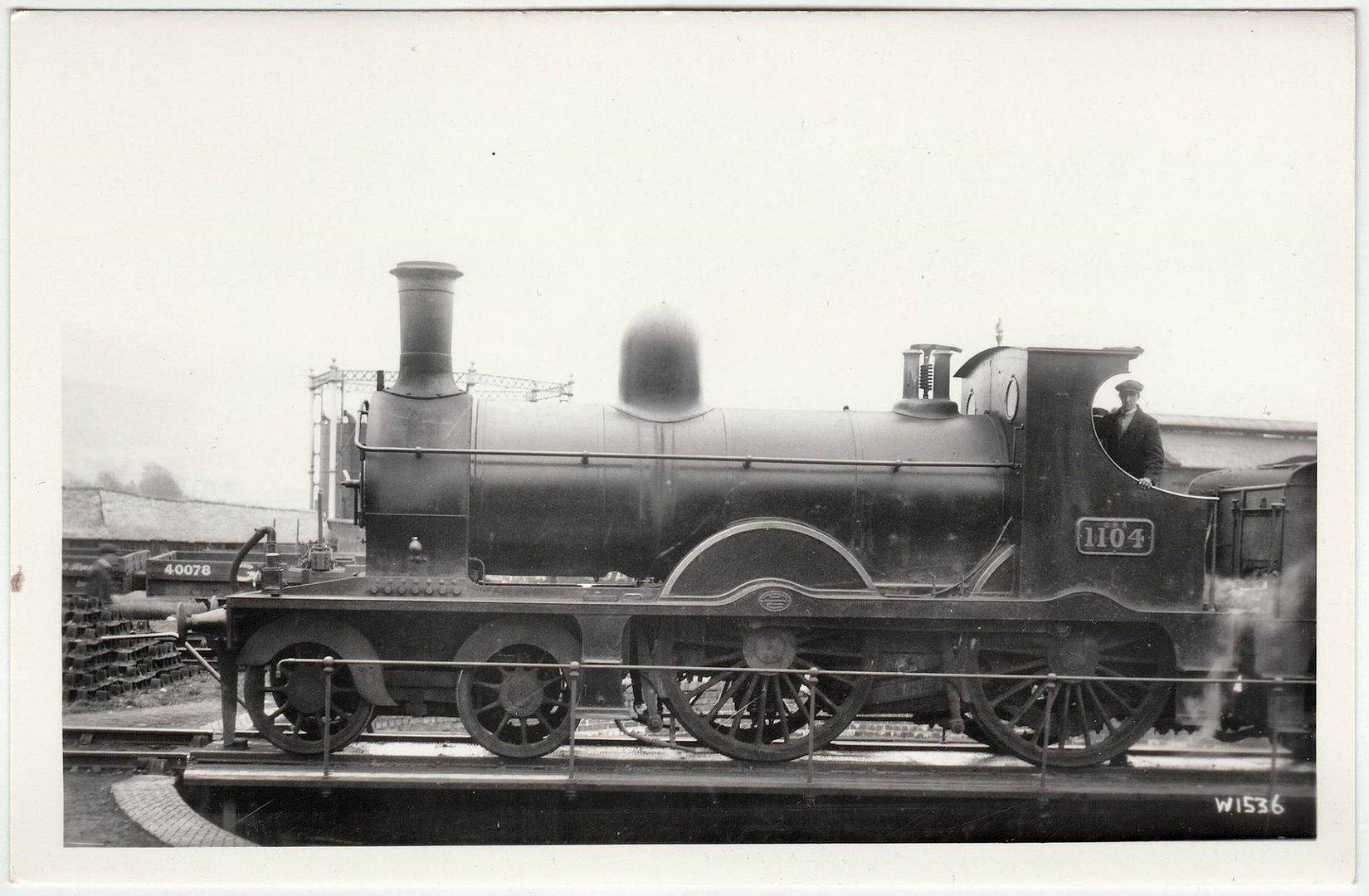
of perspectives changing, neither can the following be considered 100% accurate, however, I've been as careful and exacting as I can going only by this photograph. Many thanks to Quarryscapes for providing it...
So with that I have to the best of my ability found the axle centre of the wheels and from the front driving wheel drew horizontal lines either side. This gives us the best approximation of 6 feet. Then a circle was drew around it as best as can be done with a less than perfect angle due to perspective shift.
The bogey wheels from the top centre have a line horizontal right towards the undisputed 6 foot driving wheel - as you can see this particular bogey is 3 foot 6 inches. No arguing there.
From the 6 foot horizontal line previously mentioned that red line was copied and pasted, converted blue and divided into 6 to represent individual feet. 3 extra feet were added based on copying and pasting effectually creating a Rule/Ruler. Again, I know the perspective shifts but this exercise is to try to establish what matches what data best based on this photograph.
By placing the rule at the key areas and referring to the 3 disputed wheelbases we can see what matches best and draw some conclusions.
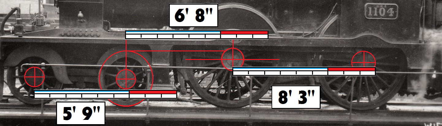
According to this picture then, I estimate the wheelbase to be
5’ 9” + 6’ 8” + 8’ 3”
Which is different to ALL the 3 above! It matches one wheelbase only lest for the value of 8'6".
So, conclusion & Questions:
A) - If the above exercise is good enough to go by (seems clear to me) then we have a 4th wheelbase that may be the median truth. If it is wrong then the wheelbase of 5’ 9” + 6’ 8” + 8’ 6” must be correct instead - I'm thinking this is likely. . The far right perspective may skew the 3 inches out of scale.
B ) - If this new wheelbase is correct then is it across the board for ALL the Class 61's or were there indeed variations?
C) - Did these dimensions transfer into the Furness K2 or is the K2 indeed different?
D) - If they did transfer and the K2 is the same, was the K2 fixed or did that have genuine variation?
Model Considerations: The Furness K2 that is available has been built with a wheelbase of
5’ 9” + 6’ 8” + 8’ 6”
This exercise shows the wheelbase to be 5’ 9” + 6’ 8” + 8’ 3” or the same if the right hand value is perspective skewed too much.
The K2 model has been designed to use the 3' wheels not the 3' 6" but if you want bigger wheels this can easily be changed by filing a little extra clearance for the bogeys and when I upload them (if you want to) getting the bigger bogey splashers. The chassis meshes can always be altered to take the bigger wheels if necessary although if this post is true the then wheelbase can stay. BUT - does the K2 indeed have bigger bogey wheels? This is still to be answered.
For the Cambrian I'm likely to use the older model that is a wee longer based on this but again I'm straining to find the truth and I think I may have found some.
Thoughts please?
Additional Issue: For the tender I have different sources with different wheelbases too. So far it is a toss up between 6' 3", 6'6", and 6' perfectly. The model is 6' 3" but currently on hold due to these issues.
The model is designed with the 3'6" tender wheels, but other sources are saying 3'10" and another even larger than 3'6" so I'm drinking whisky.
The differences are so miniscule as to be u ndetectable without a set of calipers. The exception is the bogie wheels. The Furness K2 definitely had 3' 0" ones but I am not a Cambrian expert and your measuring does indeed indicate bogie wheels of 3' 6". It wouldn#t be the first time an engine was built differently to the drawings
-
PaulR, this is my point entirely. Different sources are saying different things and everyone seems to generally believe what they have in their hand is the right answer.
Currently I'm finding the whole thing a pig. Different companies built the engines so it is possible that is where some genuine variation may have come in, same for bogey wheels...or some drawings are just plain wrong.
If it is the latter then we need to know what drawings and measurements to trust and why, because currently we're rolling around a 6ft driving wheel perpetually.
It's ok saying "This is the measurement," but why, and how do we trust what we are reading? Because a post or two below me will possibly cite one of the other measurements as the answer.
I appreciate your help a lot. Knowing what to believe currently isn't easy though. Will leave it for a bit as I gotta turn in for work sadly.
Another point has occurred to me: I used Impossible Creations for my 3D printed locos. They were way cheaper than Shapeways. Just a thought
-
PaulR, this is my point entirely. Different sources are saying different things and everyone seems to generallh believe what they have in their hand is the right answer.
Currently I'm finding the whole thing a pig. Different companies built the engines so it is possible that is where some genuine variation may have come in, same for bogey wheels...or some drawings are just plain wrong.
If it is the latter then we need to know.what drawings and measurements to trust and why, because currently we're rolling around a 6ft driving wheel perpetually.
It's ok saying "This is the measurement," but why, and how do we trust what we are reading? Because a post of two below me will possibly cite one of the other measurements as the answer.
I appreciate your help. Knowing what to believe currently isn't easy.
Knuckles,
I appreciate your difficulty. At some stage you have to make a decision. However, you have to ask yourself why would any major changes be made as between the Cambrian and FR locos? The Furness was a left hand drive line and apart from an almost indistinguishable change in the cab sidesheets, took the engines as designed, which had been done in consultation with the Cambrian Loco Supt. The Furness did not design any of their own engines until W F Pettigrew came to office in 1897. The K2s came out the year earlier
-
To PaulR.
Aye. Almost identical but not quite.
I can use the older longer body that is the same as the K2 as I never overwrote the files but there is a problem. The K2 body and splashers etc fit the K2 wheelbase, written above somewhere. The Cambrian wheelbase I just made a preliminary chassis for is different and so it threw the body fitting out the window for obvious reasons! The front splasher had to move forward, the rear whole section had to move forward not just the splasher, otherwise it wouldn't fit. I can't logically see how to sort this other than what I just did.
If you can provide solid data the help this issue I'm all ears but so far we are all (me included) citing different source material and getting a variety of answers.
It's what you call a colourful ball ache!
I quote from my copy of the GA drawings, obtained from Glasgow university library several years ago.W. Hardin Osborne also used original drawings. Rush is good on many things but is out on this one. The bogie wheels were 3' 0"


New DCC controller "ACE" from Sig-na Trak
in DCC Discussion Topics (not questions)
Posted
Will the new handset be able to work with an Ace 2? I am thinking of the new handset's ability not to have to be "taken over" from the Ace 2 itself