


2mmKiwi
-
Posts
95 -
Joined
-
Last visited
Content Type
Profiles
Forums
Blogs
Gallery
Events
Exhibition Layout Details
Store
Posts posted by 2mmKiwi
-
-
- Popular Post
- Popular Post
Hi Tim,
This photo came up on a Facebook feed, I'm sure you have it or have seen it. Based on my exposure to Copenhagen fields I thought I recognised the Potato Market area on the extreme left.
Is that correct?
SteveM
NZ

-
 19
19
-
 1
1
-
 1
1
-
Thanks Nigel - Its looks great and worth the effort- although like you, I can understand why some people don't add the wire. People might argue about the scale diameter etc but in the end the eye makes up its own mind and I think yours doesn't appear excessively large in diameter on the model, so job done.
Thanks for your response mate
Steve
-
1
-
-
Looking really nice Nigel - can I ask what you use for your fencing wire ?
It looks pretty effective
SteveM
-
Has anyone considered /used this as an alternative to Copydex?
https://www.noch.com/crafting-tips/the-practical-use-of-latex-adhesive
They claim it has sound deadening qualities which is what I want. I don't want to use PVA which sets like concrete.
For ballast alternative try Attwood Aggregates - they have a great range, but are slow to respond to requests, that's all.
Steve
-
1
-
 1
1
-
-
I'd like to see an N Scale GWR County Class 4-6-0, this locomotive is desperately needed to boost the N scale GWR representation.
A modified Hall with a Hawksworth tender would also be a great addition.
Thank you
Steve
-
2
-
-
- Popular Post
- Popular Post
The Cordon has been through the paint shop and now reflects a lifetime on the rails. This one will live at the tail end of my up milk train - hence the lamp.
-
13
-
 7
7
-
 2
2
-
On 01/12/2022 at 00:26, Yorkshire Square said:
I know it's his trainset now, but get your hands off the scenery! 🙄
Totally agree - he's standing there saying he feels like he's got a Monet, but he has one clumsy hand on the scenery and its sitting there gathering dust and cobwebs and trains not even on the tracks. It was such a shame that another UK club or the Association didn't grab this when it was for sale. I know someone will say at least he saved it, but it breaks my heart to see the layout this way.
-
1
-
-
- Popular Post
- Popular Post
In between laying track, wiring and setting up my DCC system I have been building this ex GWR Cordon, since taking these shots I've added the remaining running boards and its almost ready for the paint shop.
-
14
-
7
-
1
-
On 21/08/2022 at 21:59, Ian Smith said:
Last weekend Modbury made it's first physical appearance at an exhibition this year at RailWells. I think it's fair to say that myself and fellow operators John and Steve enjoyed our weekend but is was flipping hot!!
Modbury performed reasonably well despite the heat, over the course of the weekend 2 of the signals failed, both with the same fault - the guitar wire actuators became unsoldered from their respective levers (I use servos for the signals which have a drive rod from the rotating servo horn to a simple pivoted lever to convert the rotary motion into a linear one. The lever having a piece of springy guitar string to compensate for any excess throw).
The 6 wheeled brake van decided to regularly throw itself off the track on one of the points by about lunchtime each day (it seemed fine in the cooler morning!!). Once home I was able to test thoroughly (and closely) and as assumed there was just a little binding as the van went through the offending point. Therefore I applied the soldering iron to the affected area to provide a little gauge widening through the area.
The rake of 6 wheeled coaches were also temperamental on occasion coming off the Plymouth end train table. They were prone to derail every now and then or uncouple themselves. I think that in setting up the layout we (I) had introduced a bit of a hump across the two boards. The learning here is to make sure I include a 6" rule in my box so that I can check that the track work across the board joints is level.
The final problems were at the board joint of the other fiddle yard board. There was a step of about 6-8 thou across one rail which caused the odd derailment. We decided to live with the problem over the weekend as once we knew what the problem was we were able to shepherd the stock across the joint. The resolution once home was to lift the offending rail and solder a slip of nickel silver shim beneath the offending rail. The other issue at this board joint related to the mouse hole and the Steam Railmotor - when coming off the outermost (tightest curved) train table road the rail motor just rubbed the side of the mouse hole. The weekend fix was not to use the outermost the railmotor on tighter outer roads of the train table, the permanent fix was to carve a little off the side of the mouse hole once home.
Now some photos from the weekend :
Some of the additions to the layout prior to the exhibition - firstly I have added a little more colour to the layout with the introduction of some white and yellow flowers at the font of the layout. The rose bay willow herb, nettles and thistles have been there for a while. To achieve this, some small pieces of Woodland Scenics Polyfibre were pinched off the main wad to give me little pieces about 3-4mm in size, the tops of which were brushed over with matt varnish and some Woodland Scenics "flowers" were sprinkled onto the wet varnish. Once dry the resultant flowery clumps were set onto a little more matt varnish within the existing scenery. Hopefully, this gives the impression of the flowers floating above the surrounding grasses and weeds in a natural way. I have to thank Steve Martin for this method of adding colour to a 2mm scale landscape.

Finally, some images of the latest motive power addition to the Modbury roster - the Steam Railmotor. This attracted a lot of interest over the weekend, probably helped by Jerry Clifford (who was immediately across the room from us) encouraging visitors to "have a look at the steam railcar" 😂
Anyway here she is :
Thanks for looking!
Ian
A lovely sequence of photos Ian, the flowers look great and the variety of colours and texture in the scene adds life. I particularly like the side-on shot of the steam rail motor with the passengers silhouetted in the windows. The addition of passengers really brings the model and scene to life and you get a sense of people heading off somewhere (maybe to town to do the shopping) and the importance of the railway for connecting rural people. I would be happy to see a wisp of steam photoshopped into the photo to complete the scene - very nice!! - Steve
-
2
-
 1
1
-
-
On 01/07/2022 at 19:51, CF MRC said:
The Aussie - and other long distance travellers - made the whole Derby weekend very special. Thank you all.
Tim
Hey Tim - it was great to have a personal introduction to you and see the new additions to the layout. Thanks for brining CF to the event.
SteveM
New Zealand
-
1
-
1
-
-
Hey Jerry - will the doors be in SDJR blue? :-)
Steve
-
1
-
-
Having recently stopped at York station on my way to the National Railway museum I now have a first hand appreciation of this wonderful project.
Well done on your progress to date and best wishes for its completion.
SteveM
-
3
-
-
On 12/05/2022 at 02:31, Ian Smith said:
A little more progress on the Steam Railmotor ...
Most of the motion has now been completed on the RHS of the drive unit. Obviously, much of this is slightly over scale as in 2mm scale this stuff is flipping minute!! Effectively, each of the links has been drilled and cut to size based on what looks and works, rather than a scale version based on any drawings available. The main reason for this is the amount of throw provided by the generic 7.5mm wheel set available from the 2mm Association - I think that the scaled down crank throw of the prototype is somewhat smaller than that provided by the wheel sets used. This means that the for and aft movement of the crossheads in the slide bars is greater than it should be for example.
However, I am perfectly willing to accept such compromises so long as it fulfils my requirements of "waggling about and looking busy". This is after all a layout model not a museum piece!!
For future reference, the various linkages have had their pivot holes at the following centres :
Union Link - 2.5mm
Combination Lever - 3.5mm + 1.5mm
Radius Bar - 4.5mm +1.5mm
(These were the sizes that I eventually settled on as I had to make 2 of both the Combination Lever and Radius Bar as the originals were either slightly too long or short to provide the movement that worked smoothly).
The photo below shows the motion as it is at the minute - I have still got to make the Return Crank and the Return (or Eccentric) Rod :
At the bottom of the image are 3 failed attempts at making the Quadrant, the one for the LHS motion lies slightly above these 3. As can be seen the one for the RHS motion is in place and free to rock about a central pivot hole. For simplicities sake (and my own sanity), the rear end of the Radius Rod shares this pivot point.
The Union Link, Combination Lever and Radius Bar were pinned together at their respective junctions with small pins made from 0.6mm nickel silver wire - a short stub of wire was left projecting from the chuck of a mini drill, and a fine file used to reduce the wire until it fitted in the holes drilled in the various linkages. The chuck was released, wire pulled out a about a mm, chuck tightened and a fine piercing saw employed to cut off the wire against the chuck jaw. The resulting pin was popped in a pin vice and the head of the pin filed down to leave a little motion pin. The pins were placed in the relevant hole, a piece of cigarette paper used as a barrier, the other rod slipped on, and a flash of solder applied before the excess pin was filed back flush (or nearly so) with the rear of the linkage.
For the Quadrant and rear Radius Rod pivot, a 0.4mm hole was drilled through the bit of meat that I'd left for this pivot hole on the bent up motion bracket slide bars. For the outer bracket of this pivot point, a small piece of 0.018" nickel silver was cut and bent (having had what will be the front face thinned to about 0.010") and soldered in place suitably spaced from the slide bars by a piece of paxolin. Once in place, the previously drilled hole was used to sight the drill so that the pivot point could pass through both front bracket and rear. Then an enjoyable few minutes ensued where I tried to line up all the bits and pass another pivot pin through. Once happy, a flash of solder was applied to the rear of the pivot pin, and satisfied that I hadn't soldered it solid the same was done at the front supporting bracket (again checking that everything was still free to move!)
The reversing rod and crank were bent up from a single piece of wire that passed through the middle hole in the Radius Rod, and the crank pivot point drilled in the space left for it on the bent up Motion Bracket Slidebars (any one would think that I had actually planned how all of this lot was going to hang together reading this!!) Once happy that the bit of bent wire was the right size and shape, the bit where the crank would be was popped in a vice and squashed flat. A small piece of 0.010" was soldered onto this flat, then filed to a tapered crank shape. As it happened, the wire when inserted into the Radius Rod slightly fouled the very slight movement of the latter, so I elected to snip off the projecting wire just past the bend so that to all intents and purposes (to a casual observer, who's squinting and probably not looking too closely anyway) it appears to connect to the Radius Rod.
A further small turning provides the cylinder front face, and when all these little sub-components are joined up and hung on the chassis it looks like this :
So far I'm pretty happy as it seems to fulfil those criteria of "waggling about and looking busy". As can be seen, I've even managed to get a working valve spindle crosshead (if that's what it's called).
Thank you for looking.
Ian
Its looking the business Ian ! :-)
-
1
-
1
-
-
1 hour ago, 65179 said:
Hi Steve,
I don't know what the width of the ones Tim was recommending are:
https://www.cousinsuk.com/product/slotting-screw-head-1840-vallorbe-swiss-with-tang
However the one I have is 0.5mm:
https://www.hswalsh.com/categories/screwhead-slotting-files
They are all screw head slotting files. Mine isn't super narrow, but is nice and easy to handle.
Simon
Thanks Simon
-
On 15/02/2022 at 11:10, 65179 said:
A bit of work on the chassis.
As noted upthread I'd rushed a bit and so had forgotten to gap my pcb. In the meantime, I'd also taken note of @30368's 4mm build of 61475 and how he had swapped the initial gearbox used for a less obtrusive one part way through. My B16 posed no problem hiding the 38:1 worm on the middle axle,
but I reasoned the Association 30:1 gearbox I'd planned to use would be too obtrusive. So a change of plan:
I took a spare set of frames I had with an integral gearbox; trimmed off the unneeded bits; opened out the bearing holes for the driven axle to fit over the bearings on the inside of my frames; moved the holes for the worm inboard 0.25mm; and soldered it all up trying to keep things level by checking with lengths of axle steel through the bearings.
The missing gaps in the pcb were added by a combination of slotting file (one of the ones recommended by Tim Watson, I think during his Valour build) and scalpel.
Simon
Hi Simon, What is the width of the slotting file? I've got a bit carried away with a couple of rail joins and need to open them up for isolation purposes. Would this tool do the job?
Steve
-
Nice one Laurie - I see you won the baseboard challenge then!
It must be quite motivating to have all the baseboards in place and being able to visualise the track that will populate it.
-
On 29/07/2021 at 08:36, nebnoswal said:
And this is what I like/love about this forum. I've just about finished my 3D printed S+DJR cattle wagons and now need numbers for them. As much as I would like to purchase The Somerset & Dorset Joint Railway Locomotive and Rolling Stock Registers 1886 – 1930, and its only 8 pounds, the postage to downunder of 21 pounds is the killer! Just as I was about to the ask a question on numbers, it magically appears here. Thank-you Stephen, much appreciated.
They look nice !
-
1
-
-
On 18/07/2021 at 07:13, Bryn said:
Some oil paint weathering this afternoon on the old ambulance shed for Colwyn Bay Goods.
Nice paint job - looks quite convincing ;-)
-
1
-
-
On 08/07/2021 at 20:04, CF MRC said:
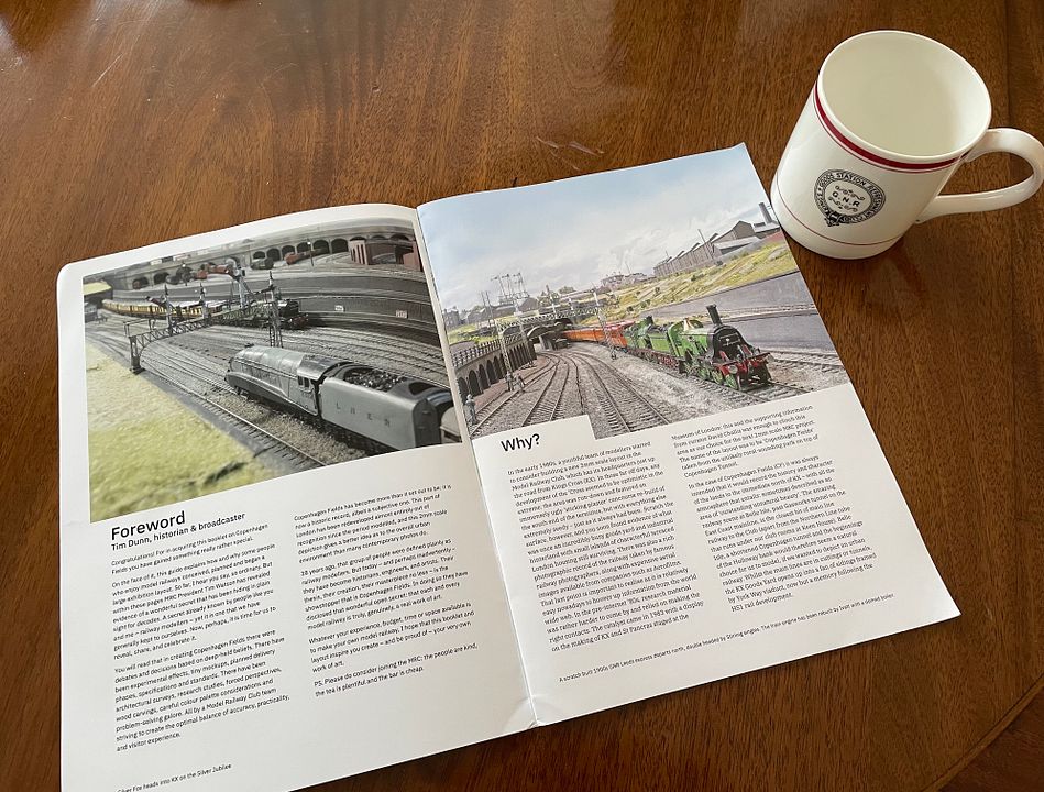
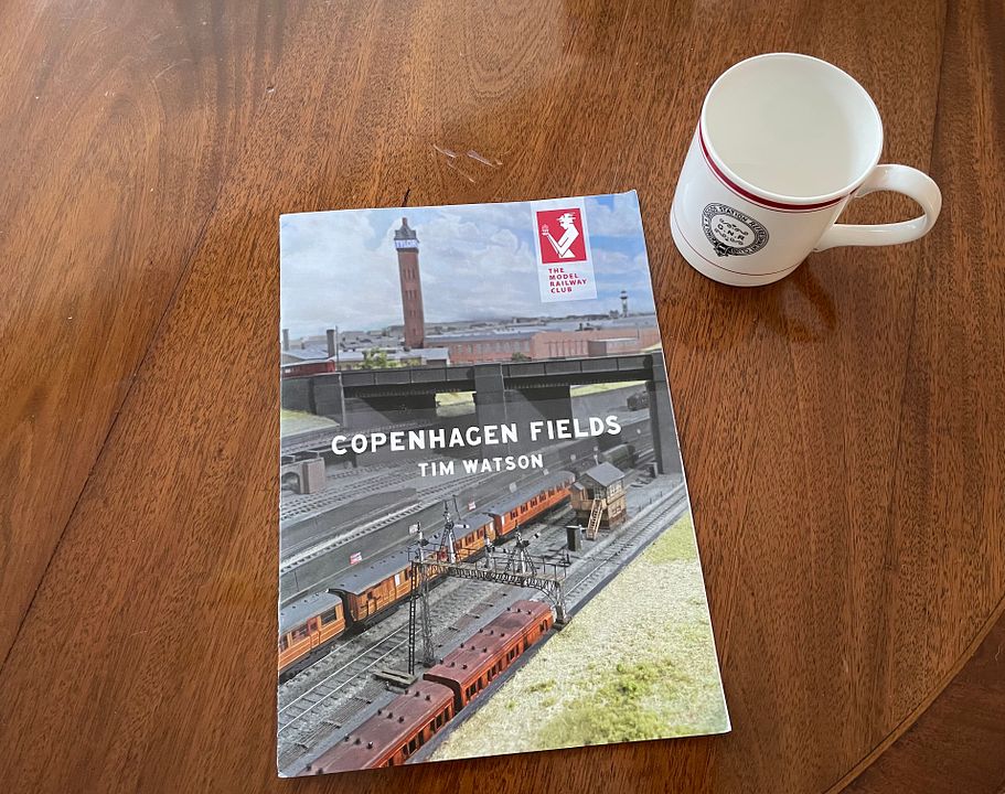
Our 20-page booklet describing the history and making of CF has now arrived from the printers. Apart form some rambling commentary, it features excellent photos taken by Tony Wright, Craig Tiley & Barry Norman and was put together by Ben Weiner. It is nice and big at A4 size (whatever else!) and printed on good quality paper. Copies will be given to attendees at our CF mini exhibition on 10-11th July and will also be available through the Club shop at £3 + £1.50 p&p - or collect from the Club. The mini-exhibition is now sold out.
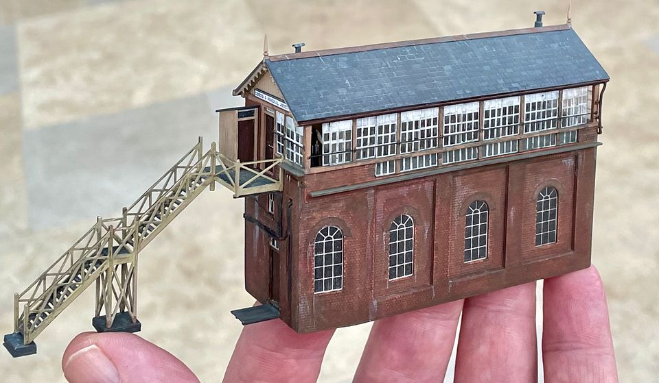
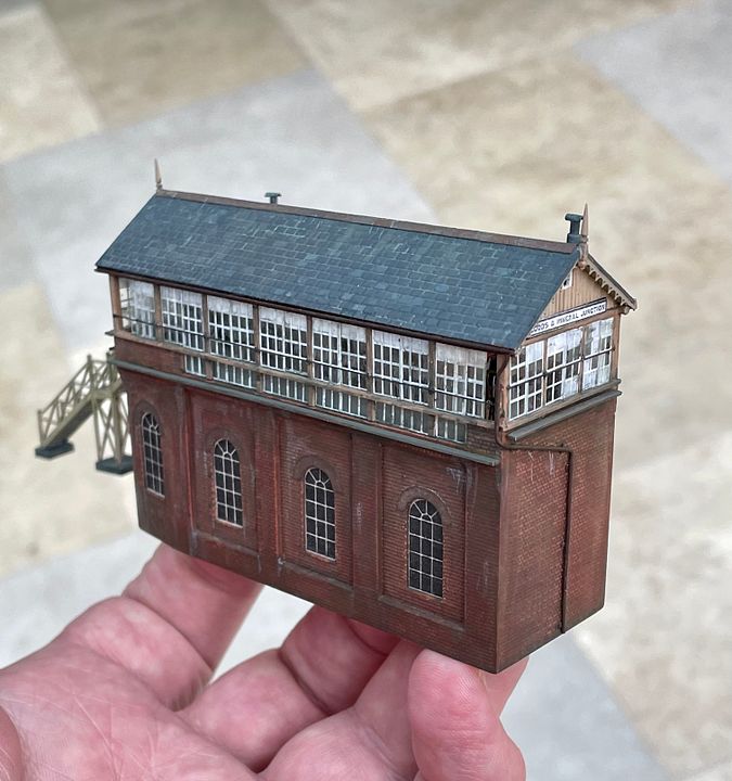
The latest addition to the layout is from Cornwall: Goods & Mineral Junction signal box, by the hand of Matthew Wald for the main structure & Jim Watt for the etched stairs, barge boards & lever frame (which is almost impossible to see).
With such a superb building now made, the surrounding areas - especially the ramp line up to the Caledonian Goods & Coal Yard - will need to be brought up to the same standard.
TimVery nice work, the roof and brickwork look particularly good - congrats to Matthew, great piece of modelling !
-
On 27/03/2021 at 15:05, dpgibbons said:
The main ingredient of lacquer thinners is acetone, which is mildly polar. So better than IPA, but not the best cleaning candidate here.
To put things into perspective, relative polarities of proxies for common solvents are (v water =1.00): IPA 0.62, acetone (lacquer thinners) 0.35, hexane (WD40 contact cleaner) 0.009. Lighter fluid and white spirit are mostly low-polarity hydrocarbons so they would be at the bottom of the scale.
However, an essential quality of a track cleaner is that it should not leave greasy residues, so more volatile hydrocarbons such as hexane are desirable. I'd guess lighter fluid is probably better than white spirit in this respect. WD40 contact cleaner looks the best candidate, but some of its rivals include lubricants and these may fail the greasy test.
Thank you for posting this very informative series on track cleaning. I was using IPA but I have now purchased WD40 contact cleaner and will try it out.
Steve
-
1
-
-
On 05/03/2021 at 09:06, queensquare said:
I was recently sent these pictures of CG by a friend. I saw it a couple of times, once with and once without LH. The first was Bristol, I was still at school so 79 or 80, I seem to remember Heckmondwyke was also there. At the time I was on the point of giving up N gauge as my two Farish locos were so poor and my Minitrix
ones worked well but didn't look great, I couldn't afford a Peco Jubilee! CG looked and worked beautifully, it inspired me to keep at it. The second, with LH, was in London I think and would have been a couple of years later - 82-83? That visit and a few influential articles in RM around that time by people like Nick Dearnley and particularly John Greenwood, persuaded me to join the 2mm Association (84/85?) although it was a long time before I successfully built anything that worked well.
The pictures are from Imrex 1980.
jerry
v
Thanks for sharing this story Jerry - look at the fine work you do now. I'm glad you persevered and it's a lesson to us all to keep going. Sharing the CG photos on this site has inspired me to expand my paradigms about the depth of scenery I can achieve on my layout. I like the idea of having sections that can be bolted to the front of the layout to give more depth. I can now see a practical pathway to adding another 1ft or so of scenic depth without creating permanent mobility and storage issues.
SteveM
-
2
-
-
6 hours ago, CF MRC said:
Steve:
CG & LH was based on the area just south of Luton in the Chiltern Hills. The mainline was Midland and the branch GN. All track was handmade using 55 thou NS strip on the mainlines. The down main could run 2mm fine scale as well as N, as it had universal turnouts offstage; the branch was FS only and added later. It was started in 1977 (using village buildings off an early N gauge layout - Gouldby for Caldecote) and was exhibited from 1979 - 1984, then sold to a country house type museum who subsequently sold it to the South Devon railway centre. They sold it on last year, but I don’t know where to. The trees used mainly scouring pads for foliage - at that time Woodland Scenics was expensive and only just becoming available and grass was made from flock fibres. Distant trees were lichen - something I still think is excellent in that situation. The back scene would certainly be made higher nowadays, but it worked well enough.
Thanks for the overview and shared video Tim. It looked like a well thought out layout and like you say in the video "the railway sits in the landscape".
Steve
PS - I didn't know you are from a farming background.
-
3 hours ago, PSi said:
Looking back — perhaps slightly off topic — some shots of the predecessor of Copenhagen Fields: Chiltern Green & Luton Hoo! These shots were taken at December 1981, roughly 40 years ago. The slides were shot on daylight film, quite under-exposed, now heavily adjusted to get something out of them. Sorry for the colours!
Thank you very much for sharing - it probably deserves a folder of its own. I hadn't seen much of this layout before, but wish I had.
I really like the depth of scenery either side of the tracks, taking real advantage of the scale in the best way. The rolling fields, hedges and trees really create atmosphere and the period buildings are superb.
Pardon my ignorance - is it based on a real location?
What happened to this layout?
Steve
-
1
-
-
Looking good Nick, you must be a bit of a night owl posted 4.00am UK time?
-
1
-


Copenhagen Fields
in 2mm Finescale
Posted
Its an astonishing display of railway infrastructure - just amazing how much is happening in this photo. What we wouldn't give to go back and look over the wall or gaze down from the bridge.
Its a great credit to the CF team that a person can identify the real items in photos from their exposure to the model.
Steve