

Laying the foundations?
.thumb.jpg.60c53fcbcaa34017b05b8919d1a9e6d2.jpg)
Entry posted by Silver Sidelines
4,656 views
How to construct the baseboard? This question seems to be asked on a regular basis. I will describe my own experiences.
The woodwork in progress
I have used the same basic approach for all three of my ‘big’ layouts. I would say it is my variation of the ‘L’ Girder technique.
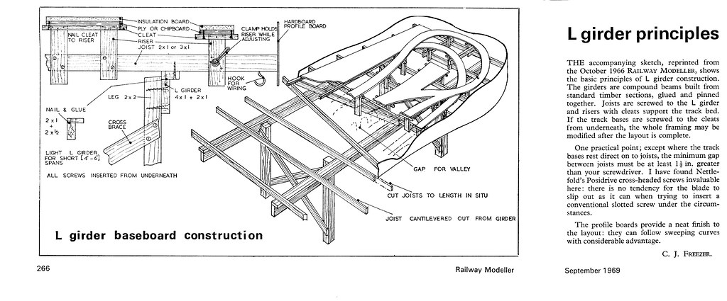
’L’ Girder overview according to CJ Freezer
I spent some time this weekend searching through old periodicals to see if I could find the original article that inspired me to use the ‘L’ Girder technique. No luck – I think it was a US layout. I did find an article in the Railway Modeller from September 1969 which linked back to an earlier article from October 1966 which I do not have. These articles provide a useful overview of the technique but differ slightly in detail from my own practice.
For my basic structure I made ‘L’ girders by screwing and gluing 1x2 inch planed timber to the top of 1x3 inch planed timber to form an inverted ‘L’. PVA provides the bond and a few strategically placed screws provide the clamping action. I have used these sizes of timber to make girders successfully up to 10 ft long.
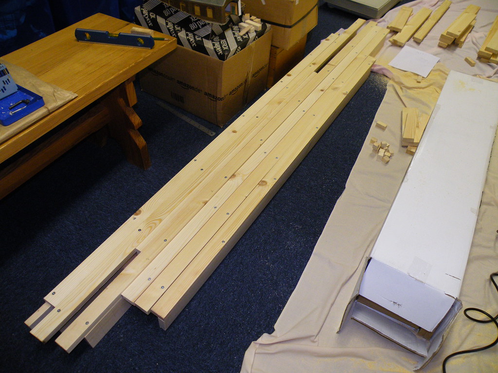
Stash of ‘L’ Girders
The ‘L’ Girders are then joined together to form a rigid frame. I form joints between girders by overlapping the 1x2 inch timber from one girder to match a similar sized cutout in the other girder. This can be done at the ends or in the middle to make cross joints. Again I use PVA to form the bond with a screw to provide the clamping action.
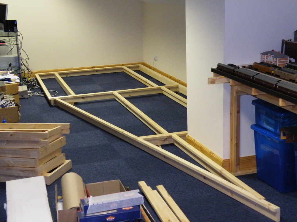
The rigid frame for the Extension
Where the layout completely occupies a room it is possible to hang the whole frame from a 1x2 inch batten screwed to the walls around the room (without the need for legs).
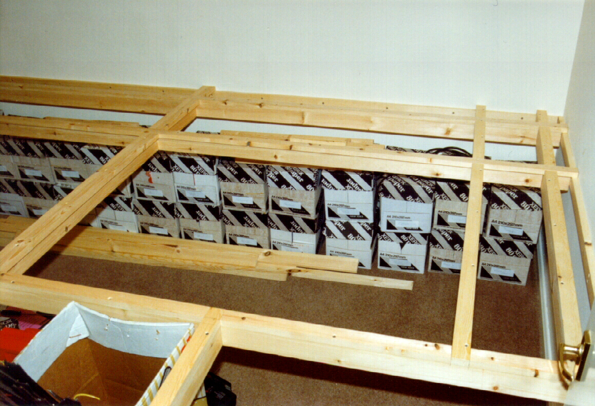
’L’ Girders hung from battens screwed to walls
Where the layout is to be free standing I have made legs from 2x2 inch sections. These are both expensive and difficult to cut and latterly I have fabricated supports variously by screwing and gluing 1x2 in sections to 1x3inch sections to form trestles.
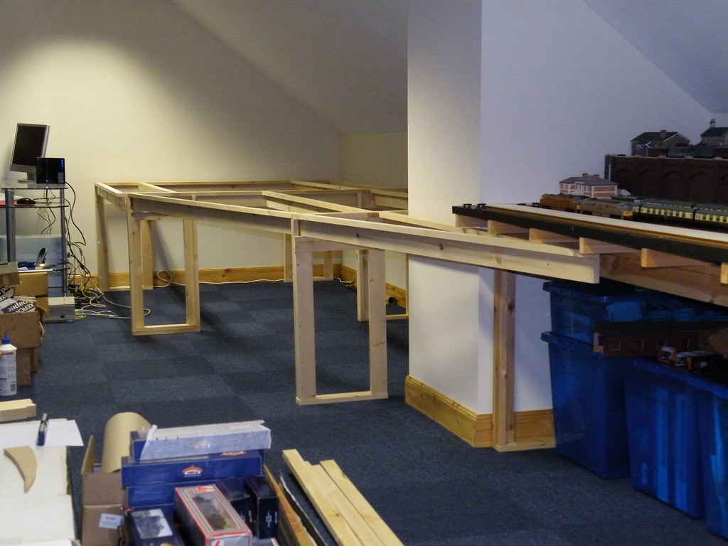
Girders supported by trestles
Support for the railway is provided by 1x2 inch joists screwed and glued across the tops of the ‘L’ Girders. Joist positions are determined from the track layout, not forgetting where you might want point motors! Where the layout is to be flat such as for stations, sidings and depots, and where a continuous sheet of board is preferred, the joists can be equally spaced at say 12 inch centres overlapping the underlying ‘L’ Girders by as much as 6 inches.
Adding joists
The joists are screwed through the flanges of the ‘L’ Girders from underneath. It makes sense to mark the positions of the joists on top of the flanges and to drill the screw holes from above.
Having laid the foundations so to speak the railway ‘board’ can be laid across the joists and any excess material (weight) removed.
1/2 inch medium density fibre board (MDF)running surface
Excess MDF removed where tracks or heavy buildings not required
At the corners of the room where curved track is required it can be convenient to arrange the joists in a fan shape.
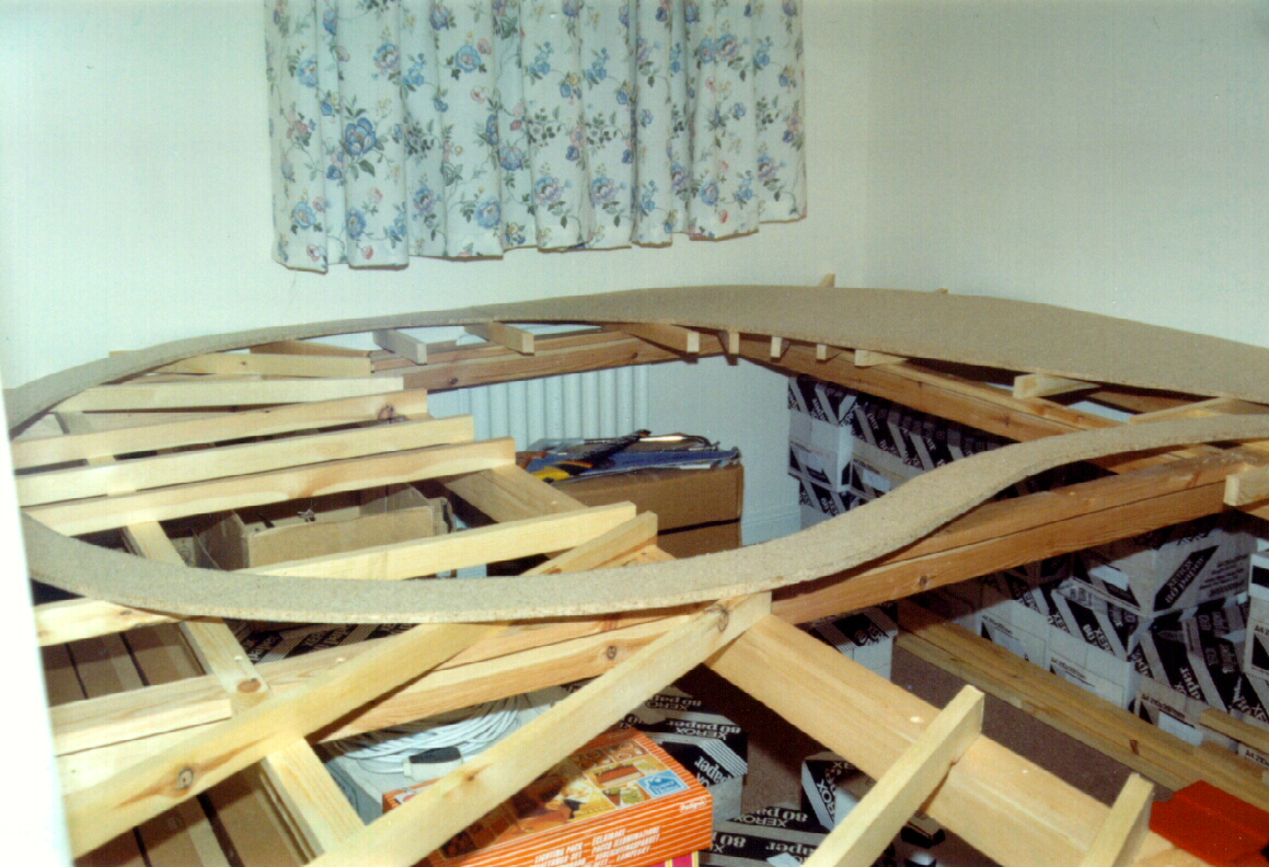
Joist positions for curved track – an earlier layout using 1/2 inch chipboard surfacing
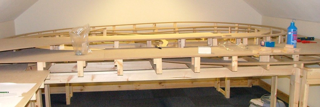
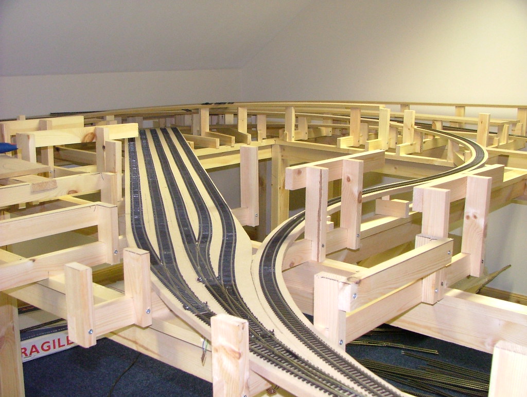
The real advantage of ‘L’ Girder construction is the techniques ability to support multi levels and tracks with different gradients.
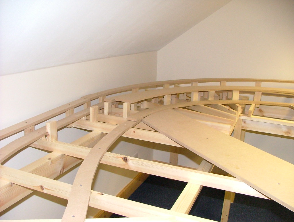
Support for multi levels with gradients
Instead of screwing the baseboard material directly to the cross joists the track bed is mounted on vertical supports cut from the 1x2 timber sections.
Creating supports – early version
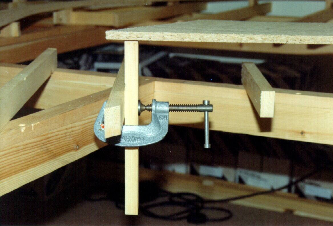
In the past I would clamp the supports in position before cutting to size, and screwing and gluing using the long face. For the current layout I turned the support through 90 degrees and used a jigsaw to cut a notch at the bottom of the support to locate it onto the joist.
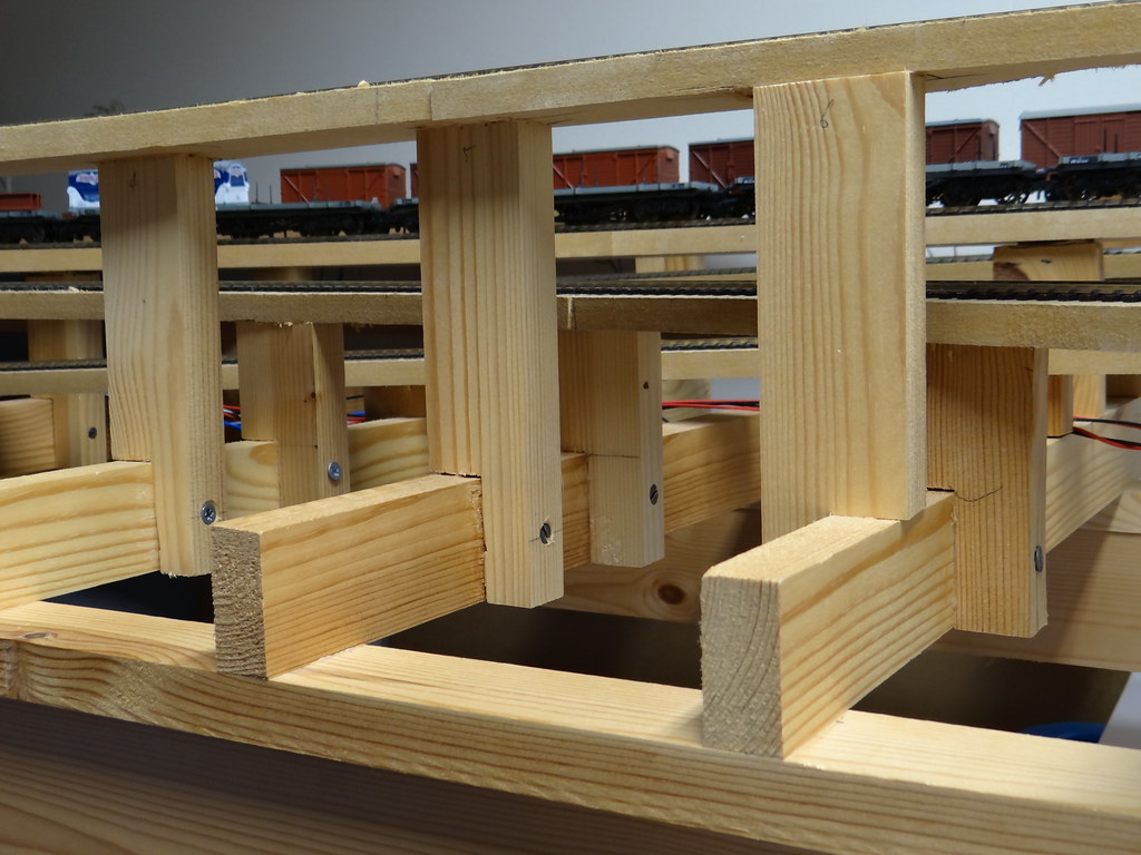
Close up of supports located on joist, bonded with PVA, screwed to provide clamping action
Using this approach the vertical support can be glued and lightly held in position whilst the clamping screw is tightened, without the need for extra pairs of hands or temporary clamps. It should be noted that the horizontal spacing between supports on adjacent joists has to be greater than the length of your screwdriver plus the size of screw that you are using (otherwise you cannot tighten the screw)! I would usually use ‘Philips’ type screws but where the spacing is very tight I have had to revert to conventional screws that can be tightened with my old short stubby screw driver.
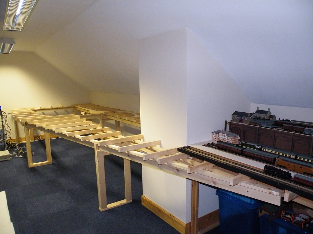
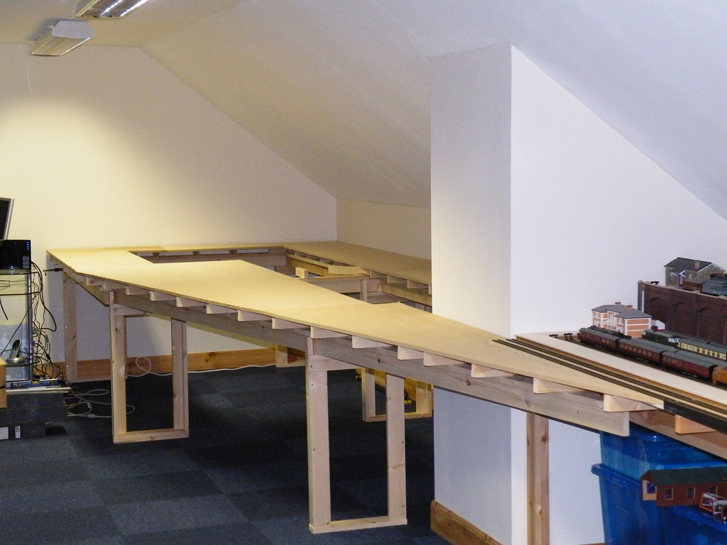
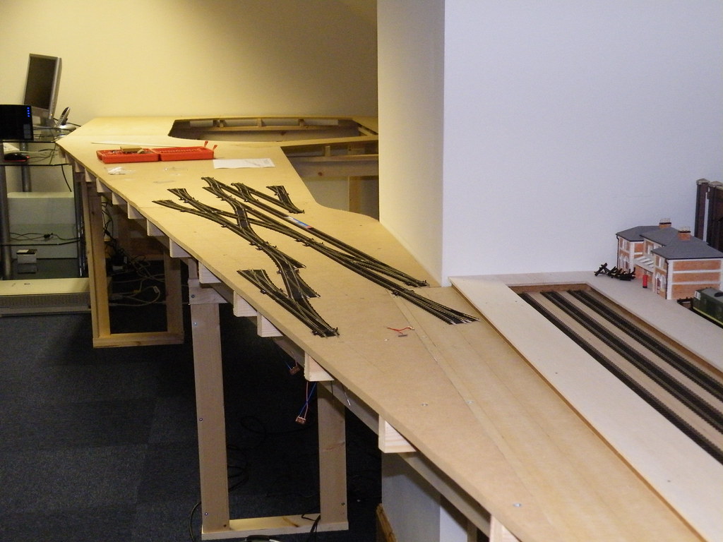
For stations and other ‘flat’ areas at high level, I have added cross members (joists) at the higher level supported by pairs of vertical supports from the joists at low level. The two pictures below are essentially the same location. The first shows the vertical supports whilst the second view below shows a ‘dry run’ with the high level boards cut to size prior to laying the storage sidings beneath.
Lots of support
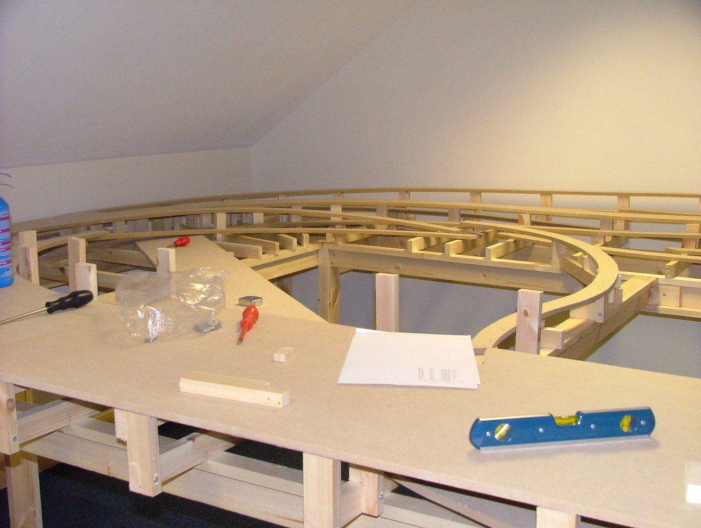
Dry Run with High Level boards
With this form of construction there is no need for continuous heavy framing beneath the higher level boards and hence the clearance between different levels can be kept to the absolute minimum (2 1/2 inches for 00 gauge) to minimise track gradients between levels. In fact at a critical point on a previous layout I stopped the overlying boards short of the underlying track and bridged the space with brown paper. The ‘gap’ of perhaps 2 inches was easily bridged by the overlying Peco Streamline track and I saved a very valuable 1/2 inch in height which went to reduce the ruling gradient.
I fixed the MDF baseboards to the vertical supports using PVA and screws. It makes life easier to cut and position the MDF board prior to fixing (a dry run) and to draw round each support with a black marker pen from the underside. The board can then be turned over and the required screw holes drilled from underneath all in one operation.
One advantage to this form of construction is the ability to handle rail layouts with curved tracks and adjacent differing up and down gradients.
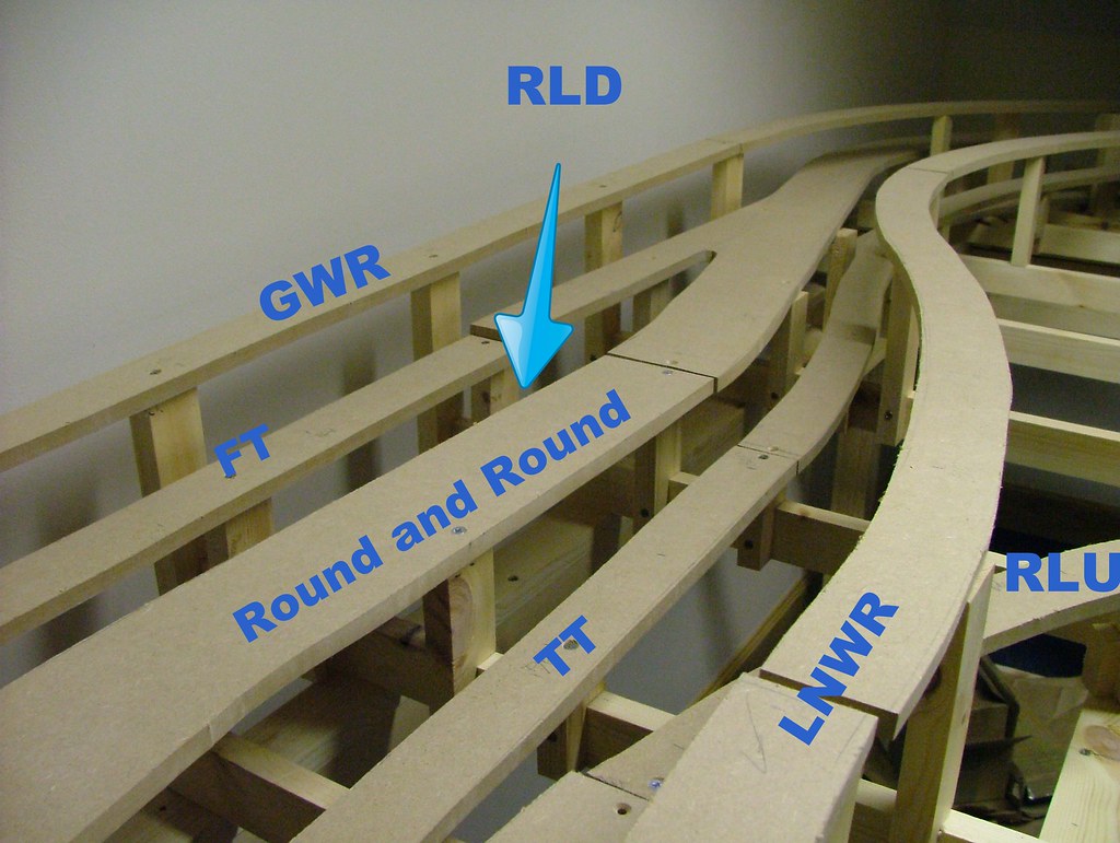
Supports for multi level gradients
(FT=from terminus, TT=to terminus, RLD=reversing loop down, RLU=reversing loop up, GWR=exGWR single line, LNWR=exLNWR single line)
Since the joists are screwed from beneath, they can in theory be removed and repositioned. This is not something that I have needed to do. I have added extra joists and vertical supports when I have wanted to extend high level station layouts. The vertical supports from the joists can also be removed, all be it using hammer and chisel. This too I have done where gradients did not turn out as hoped. On a positive note, the strength of the PVA joints needs to be seen to be believed and the combination of ’L’ Girders, joists, vertical supports and overlying MDF board makes for a very strong ‘box’ like structure reminiscent of the hollow sections and box girders used in prototype structures.
The dust from cutting and drilling Medium Density Fibre Board is considered to be a health hazard. I carried out all major cutting and drilling outside in the fresh air. Prior to layout construction I made 1/2 inch to the foot scale plan of the main boards, which I then cut up with scissors and rearranged in the manner of a jigsaw to see how best economically to cut up the 8x4 sheets. Outside in the fresh air the sheets were laid out on upturned plastic crates, marked out with a back pen and cut out to the required shapes using a jig saw.
-
 8
8

2 Comments
Recommended Comments
Create an account or sign in to comment
You need to be a member in order to leave a comment
Create an account
Sign up for a new account in our community. It's easy!
Register a new accountSign in
Already have an account? Sign in here.
Sign In Now