

Positive Switches - Peco solenoids and CDUs an update
.thumb.jpg.60c53fcbcaa34017b05b8919d1a9e6d2.jpg)
Entry posted by Silver Sidelines
2,446 views
A few weeks back I posted some thoughts on the need for and the use of Capacitor Discharge Units (CDUs) with Peco solenoids. I reported that after some thirty years of model train operation I had now installed my first Capacitor Discharge Units.
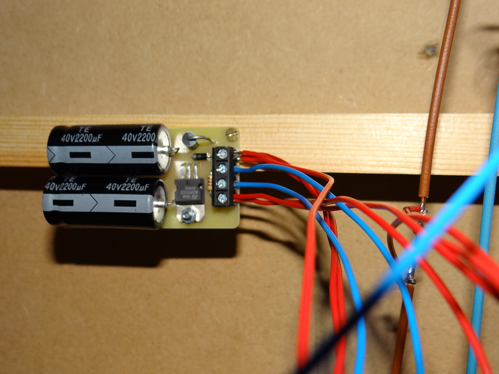
Under baseboard Gaugemaster Capacitor Discharge Unit
At the time I did not see a great improvement in point operation. In a couple of cases the operation was worse after installing the CDU than previously with the power supplied directly from 16v auxiliary supply from my Gaugemaster DS controller. I suggested that the there was a problem with the quality of the push button momentary contact switches that I was using. Some of these switches had been in use for over thirty years on three different layouts. It was explained that without a CDU there was likely to be problems, not with operating the solenoids but with switching the current off after solenoid operation. Further that switching off larger currents as needed to operate two points at once would cause sparking at the switch contacts leading to erosion of the contacts and hastening switch failure (burn out).
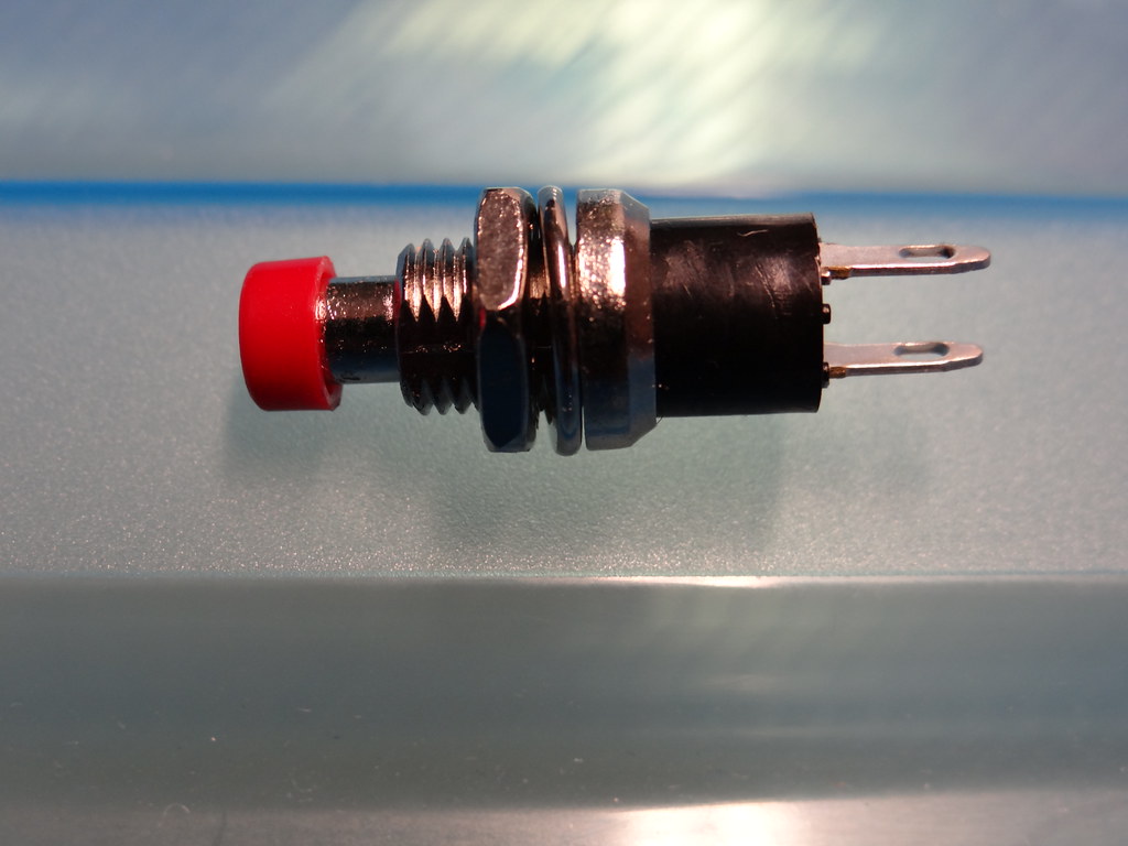
A better switch – 1amp rating - 30000 operations
I deduced that my old switches were worn out. Over the last few weeks I have replaced all (well almost all) the old switches from previous layouts – 100 in total. There is now a noticeable improvement in point operation - very satisfying.
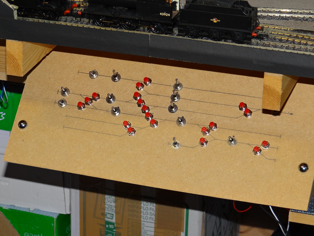
Refurbished Panel for the Branch Terminus
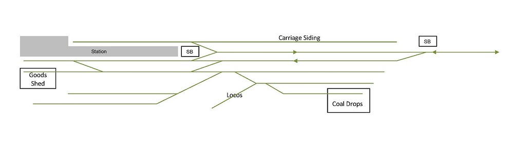
Branch Terminus Track Plan
The Branch Terminus panel was the first to be constructed for the present layout. All the switches were old and hence they have now been replaced. For interest I have also included a drawing of the actual track layout. It is worth comparing the track plan with the control panel and noting the number of switches at crossovers where one switch would be operating two point motors.
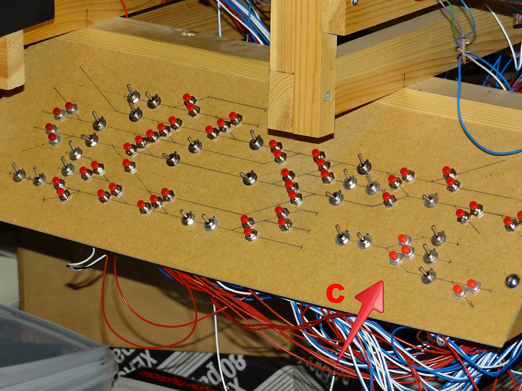
Refurbished Panel for the Main Junction
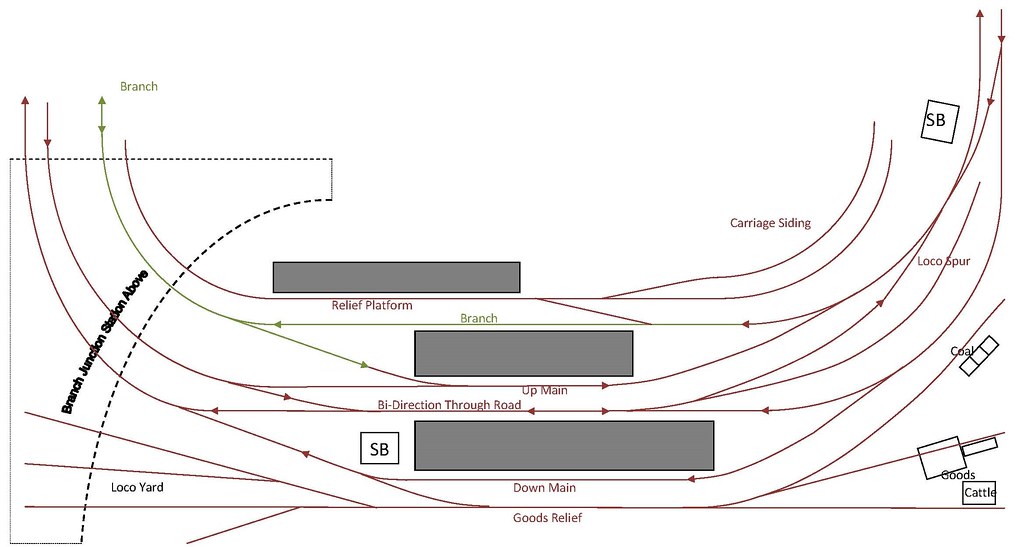
The Main Junction Track Plan
The Main Junction panel also contained mostly old switches. Again I have included a drawing of the track plan for comparison. This panel has additional switches for the points accessing the reversing loop. Also the panel includes the switches (marked with a letter C) for the diesel depot off the Track Plan in the ‘far corner’.
Refurbished Panel for the Main Terminus (that was)
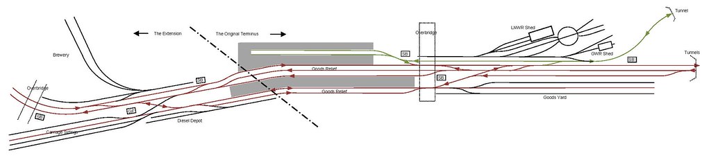
The Main Terminus Track Plan
The Main Terminus panel was the third panel to be built using the old switches. Again for interest I have shown the Track Plan. As originally built the Main Station was a terminus. It was only more recently that the layout was extended and the terminus station converted to allow through running. The switches for the extension were all new and built into a separate panel at the extended end of the station.
Those of you with eagle eyes will notice the single white switch and the adjoining offset red switch that were added when the original diamond crossing was swapped for a single slip point to provide better running characteristics without so many dead frogs. Actual use of the Peco single slip is banned as the radius is far too tight for my close coupled rolling stock.
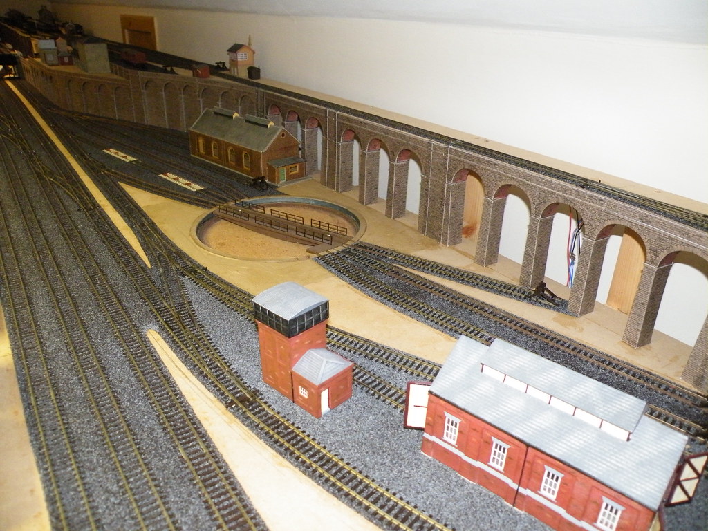
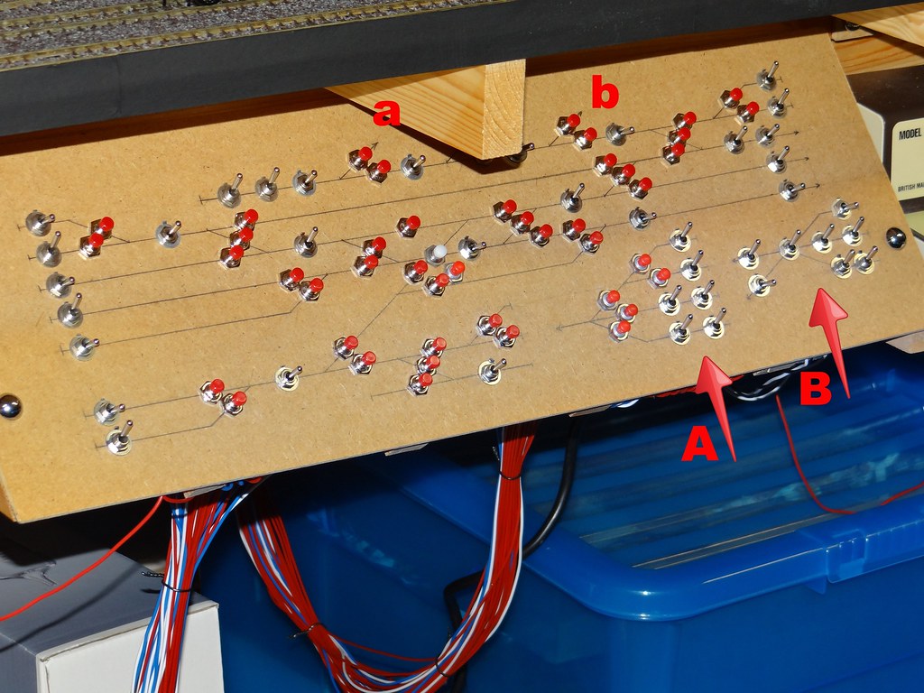
Shed Yard and Turntable Tracks during construction
In order to keep the Control Panel to a size that could be fitted beneath the baseboard the switches for the three way point in the shed yard, and the section switches for the tracks around the turntable were positioned in convenient empty spaces at the bottom of the control panel marked A and B respectively.
I would say a good outcome. After thirty years of use I guess I should be happy to buy some new switches.
-
 4
4

4 Comments
Recommended Comments
Create an account or sign in to comment
You need to be a member in order to leave a comment
Create an account
Sign up for a new account in our community. It's easy!
Register a new accountSign in
Already have an account? Sign in here.
Sign In Now