


Entry posted by johnteal
1,167 views
Several updates all in one now RMweb is back online....
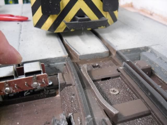
Points ... The Big hand from the sky was not ideal, so out of interest I checked the amount the blade moved in relation to a OO point motor... and guess what it was the same... Next problem how to convert the linear motion of the motor to the rotary motion of the point control, after some thought I gave up and went for plan B, how to connect the motor to the blade and came up with this...
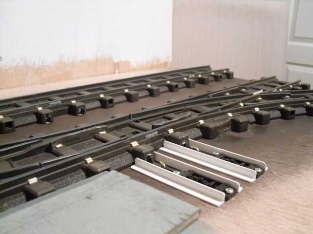
A small hole drilled in the end of the blade an a 90degree bend on the end of a rod. All the original mechanism removed.
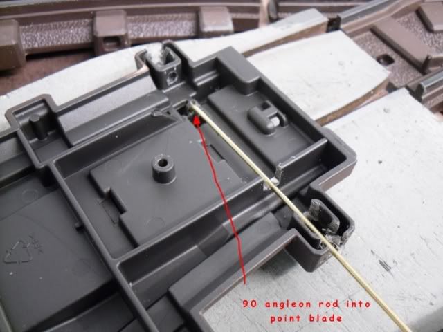
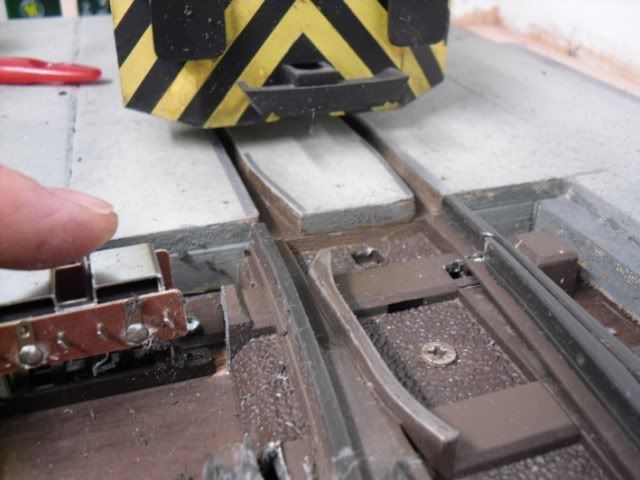
From above the end of the rod can just be seen.
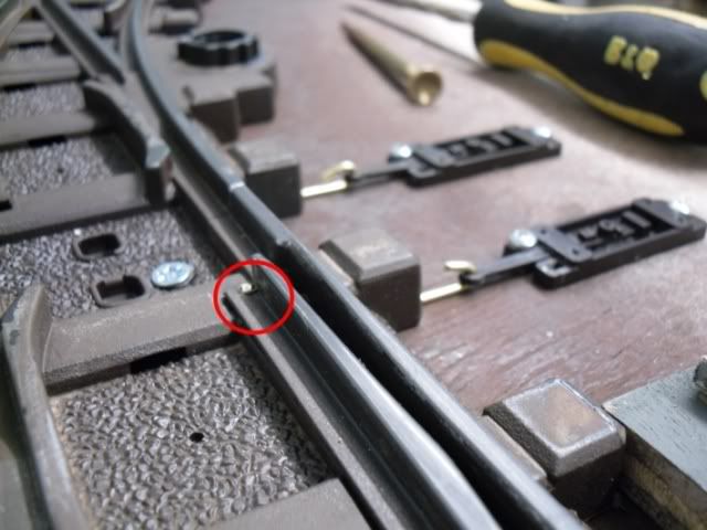
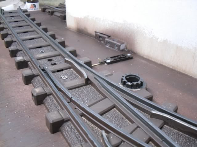
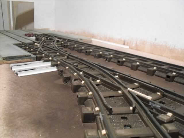
Another 90 degree bend at the other end of the rod and a surface mount peco motor base for each one
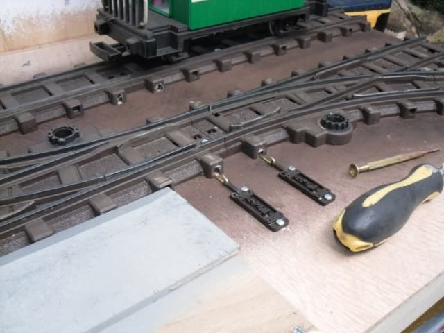
The rather large original plastic control block could then be cut off the side of the points
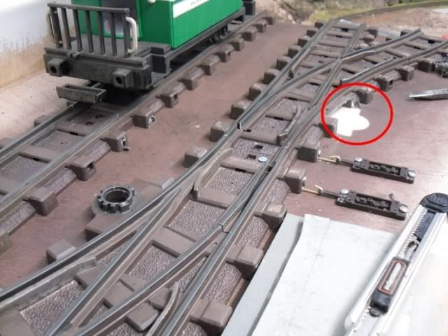
in this shot all the lumps have been removed, these areas will be reworked with a sleeper end.

The motor/blade movement
The other end got the same treatment, base and rod added, unwanted plastic trimmed off
Then another night I went cross eyed sticking bits of matchstick on to give a feel of chairs along the track, Missing guard rail on each point set added too !
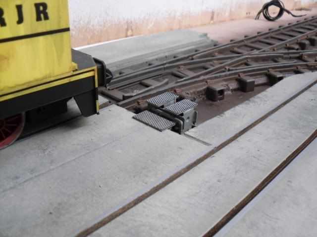
I also started to build out to the point motors, to be cunningly disguised as point motors ! I have been wondering about using the upstanding point motor rod for a ground signal, but it may just get clipped and some checker plate over the top of each, time will tell
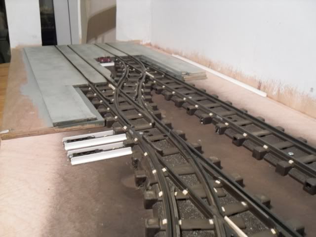
Finescale its not but I think it is starting to loose its toy look now??
Then yet another night without RMweb to distract...
Attention turned back to the points.. As originally I hadn't planned to have any electrickary involved, the twin skin baseboard construction seemed a good idea. Now faced with fitting wires I had a decision.
Option 1 was to run the wires above ground level in ducting, but this still meant going under tracks a couple of times.
Option 2 feed the wires between the plywood faces.
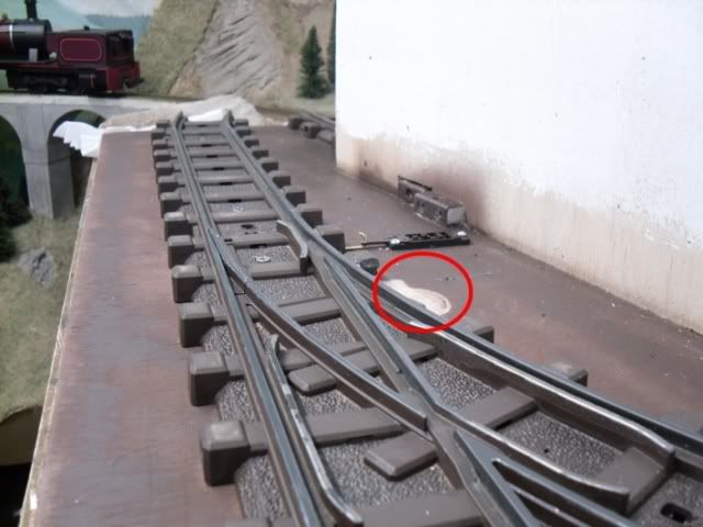
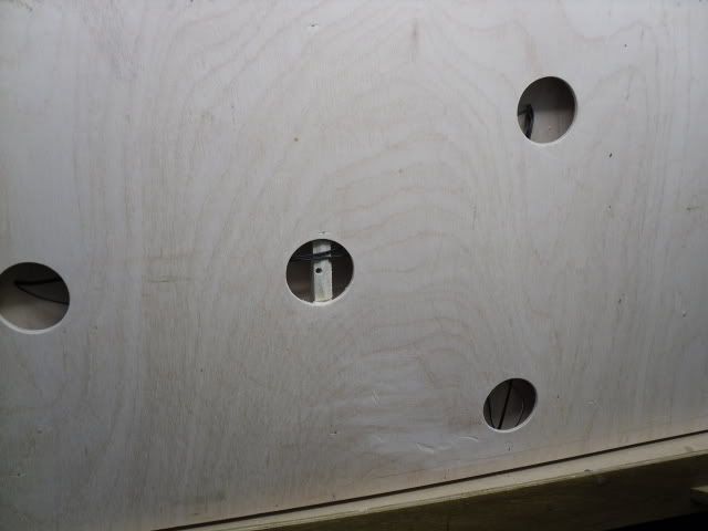
I decided in the end on option 2 which turned out pretty easy. 1st job was to drill some 2.5" access holes under where the point motors fit.
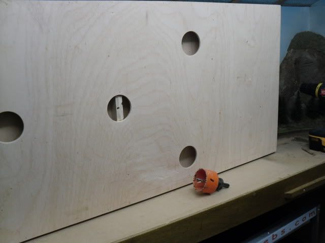
Then with some small holes drilled through the top skin wires were "weaved" in
With after thought I may have been able to mount the motors in this cavity but I think they are going to look okay above ground.?!?!
The one motor I had in stock has now been wired in the most awkward position of them all and tested with a 12v supply, it works fine.
The next step was some disguise, the plan is to disguise as a point motor ! albeit perhaps oversize. The results so far
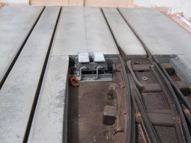
A lot of the bottom will be lost under ballast.
And now your all back up to date with what I've been up to
John
1 Comment
Recommended Comments
Create an account or sign in to comment
You need to be a member in order to leave a comment
Create an account
Sign up for a new account in our community. It's easy!
Register a new accountSign in
Already have an account? Sign in here.
Sign In Now