


Northmoor
-
Posts
4,492 -
Joined
-
Last visited
4 Followers


Recent Profile Visitors


Northmoor's Achievements
22.9k
Reputation
Bookmarks
-
Hornby Class 86 Detailing
Hornby Class 862 hours ago, MGR Hooper! said:Can you give me a reference number for the pantograph you used on the Freightliner Class 86?
Hi MGR. it’s a Sommerfeldt 925. I managed to find a few for sale on eBay a few years ago.

Cheers
Darius
-
Class 141 Modelling
Jonathan's Modern Image Workbench (3D-printed class 323 EMU, class 156s, 3-car 144s, a 141, 4-car class 465s)Not much has happened of late, but one body is complete. I still think it will be much too tall, I'm thinking that I'll invest in a Realtrack chassis rather than Hornby which should at least make it sit better as well as run better, even if it costs quite a bit more - although considering that most Hornby 142s seem to go for £60+ on Ebay anyway, its not that much more for a new Realtrack 144.


-
Hornby GWR Coach Livery Paint Codes
Wright writes.....8 minutes ago, Headstock said:Good morning Ian,
if you get a decent paint finish on that set, it will be far better than the Hornby version. The latter are very good models, but Hornby are not very good with colour and the 'jam jar' window effect can always be bettered by glazing on brass carriages. Your interiors are very nicely rendered, I especially like the light wood panels that looked so distinctive on these carriages when viewed through the corridor windows.
Hello Andrew,
These will be done in crimson and cream; I'll use Vallejo Carmine Red and Humbrol Cream (RC424). I find the Humbrol a bit gritty through the airbrush but hope to get a clean line between the two colours for the lining to sit over. I haven't found a suitable cream in Australia. You're right about the glazing on Hornby's, although I don't think the Maunsell's are as bad as the Bulleid's they do. I have cut the glazing for these from glass microscope slips, I think glass does make a difference. The interior panelling is a distinctive feature and the brass etching has the panels marked so it was reasonably easy to paint them.
Cheers,
Iain
-
Class 52 Western Livery Data
WESTERN LIVERIES 1961 - 1977WESTERN LIVERIES D1000 - D1073, December 1961 - February 1977
-------------------------------------------------------------------------------------------------
With the much awaited Dapol Western looming over the horizon, what follows is a list of all known liveries carried by all seventy four class members from D1000's entry into traffic on 20th December 1961 to that fateful, final railtour on Saturday 26th February 1977 when D1010, D1013, D1023 and D1048 bowed out in fine style. It's often perpetuated in print that the entire class wore the same maroon livery in the sixties, with some authors repeating other's previous mistakes down the years, however this was never the case, as three locos bypassed the livery altogether by going straight into blue from their earlier, green colour schemes, namely D1004 (into BFYE), D1036 (into BSYP) and D1037 (into BSYP). The only livery carried by the entire class at the same time was Blue with Full Yellow Ends, from 3rd January 1972 onwards, which was the day D1057 was released from Swindon Works, it being the last to receive this livery.
Livery dates are listed in order of application, the dates themselves referring to the day they were released from Works. It's not unreasonable to assume that the actual date of painting would be some weeks beforehand and it would have taken several days to paint each loco, but these 'released from Works' dates are the best way to keep things in order. Once each loco had been released to traffic from new, whether from Swindon or Crewe, it was always Swindon's responsibility to carry out any overhauls and repair work, the only exception being when Laira Depot was granted permission to do loco repaints only in 1972. Withdrawal dates were often days, weeks or even months after the loco had been switched off for the last time and in several cases were the result of collision damage, fires, etc.
I've included mention of the experimental windscreen wipers and air vents carried by certain locos as they relate to the liveries carried at the time. Regarding the wipers, most of the equipment was removed fairly quickly but some of the mountings for them remained in situ until the locos were withdrawn. D1023 is reputed to have had horizontal wipers fitted in 1967 but photographic proof has eluded me so far... Adrain Curtis's booklet on D1023 may have something on it though, alas I don't have a copy so if anyone else does please get in touch! Surprisingly, photos of Fusilier during this early period in it's life are quite rare.
I'm not going to weigh this thread down with a debate on the existance or otherwise of so called 'chromatic blue', which for all intents and purposes was rail blue applied to the bodywork of seven Westerns possibly using a different undercoat and an 'airless' spraying system. We could argue the toss till the cows come home but one of the first colour shots ever taken of D1030 in it's striking new 'BSYP' livery shows the actual shade of blue to be as close to 'normal' rail blue as makes no difference. The shot I'm referring to appears in several books and magazines and shows the loco on public dispaly at Taplow (I think) alongside other rail blue vehicles.
So - some general notes to start with then on with the list proper...
Livery codes :
MNYP = Maroon / no yellow panels
MSYP = Maroon / small yellow panels
MFYE = Maroon / full yellow ends
GSYP = Green / small yellow panels
BSYP = Blue / small yellow panels
BFYE = Blue / full yellow ends
(WD) = Withdrawn from BR service
Roof hatches :
On maroon locos the removable hatches between the cabs were black, on the seven green locos they were mid-grey, on all blue locos they were blue regardless of whether they had small yellow panels or full yellow ends. On all locos, the removable hatches directly above the cabs were body colour.
Bufferbeams :
This is where it starts to get complicated.... the Devil really is in the detail!
On the early maroon locos without yellow panels (D1001, D1005 - D1010, D1039 - D1043) the bufferbeam area and buffer stocks were an unusual shade of yellow, some say almost lemon in colour. On the Swindon built locos this yellow was applied to the flat / vertical part of the bufferbeam area and the vee shaped bevelled edge at the bottom only. Crewe Works had their own idiosyncratic versions of this, with D1039 and D1040 having the yellow extended to the entire bevelled edge including the raised lip surrounding it, while D1041, D1042 and D1043 had the yellow going as far as the bevelled edge only, but not the raised lip. In some black and white photos it's difficult to see these variations when dirty, but they are there. Some colour photos often show this yellow to vary in tone quite a bit with some looking very pale and others looking much darker, but probably the best example of what it actually looked like in service is in Roger Geach's book 'Westerns - Back To The Old Days' which has a fine shot of D1040 hammering south towards Hatton in February 1963, with the painted 'raised lip' also clearly visible. This particular shot also illustrates very well just how dirty the maroon livery could become quite quickly, since D1040 was only five months old at the time. These yellow bufferbeams were all painted black when the locos concerned gained their small yellow panels.
All subsequent maroon locos (and repaints from other versions into maroon) had black bufferbeams and buffer stocks..... from scouring hundreds of colour and black and white photos, it appears that Swindon built locos had the black applied to the vertical areas and vee shaped bevelled edge at the bottom only, while the Cewe machines had the all of the bevelled edges painted black as well, but not the raised lip surrounding them. Its very difficult to tell in some photos though, I think the only sure way to know for certain is to find an ex-works photo of your chosen loco.... not that easy with some of them!
All green locos had red bufferbeams and buffer stocks (and matching name and numberplates). On Swindon built D1002, D1003 and D1004 the red was applied to the flat vertical areas and the vee shaped bevelled edge at the bottom, whilst on Crewe built D1035, D1036, D1037 and D1038 the red extended to the entire bevelled edges but not the raised lip surrounding them.
With one exception, all blue locos had black bufferbeams and stocks, the odd man out being D1030, which had red bufferbeams and buffer stocks when it went into early blue livery in August 1966, which it kept until it received the by then standard BFYE in April 1970. On this loco, the red extended to the bevelled edges of the bufferbeam apron but not onto the raised lip around it, which was blue. Since all BFYE locos had black bufferbeams, this notation has been left off the individual loco list to save space!
Window pillars :
D1001 had white window pillars but all subsequent maroon locos had grey / off white pillars, the paint spec for which was very likely the same as that for the Hymeks. It became very dirty early on and looked darker after a few months service. All seven green locos had green pillars and the seven early blue locos all had blue pillars. This feature on green and early blue locos makes them easier to identify in certain black and white photographs. All locos which received full yellow ends, whether in maroon or blue, had yellow pillars, with the yellow extending right around the side windows, under the roof peaks and on the horizontal ledge below the windscreens. The changeover point between the full yellow front and the body colour occured just round onto the vertical sides at each cab corners, it's a very subtle Western trait this, and definitley part of their later character!
Name and numberplates :
Aside from the severn green locos which had red backed plates from new, all locos had black backgrounds to their cabside number and bodyside nameplates from the start. The red plates were subsequently all painted black when each of the locos were painted blue, and this was the standard for the entire class apart from the occasion when D1013's plates were painted red at Laira in April 1976, due to it's new found status as 'official' railtour engine. It kept these red plates right up intil withdrawal in February 1977. There's been a bit of an urban myth doing the rounds that D1029 also had red plates for a while, but since this idea is undoubtedly based on a black and white shot of it in blue livery in it's later years (where the plates themselves look slightly washed out) and no other evidence has come to light, I think we can safely say that it didn't.... unless of course, you know different....
 . In their later years, the cleaning agents used in the WR's carriage washing plants not only ruined the blue paintwork on the bodysides, it also scoured away a lot of the black paint that had been applied by hand onto the name and numberplates, making them look very pale in certain b&w photos. It's worth mentioning here that D1000's nameplates were of a non standard size, the backing plates being the same depth as the numberplates. All other Westerns had the standard shallower height plates. There are several photos of D1062 wearing similar non standard plates parked up by the old turntable outside Swindon Works after it was saved for preservation, but these are replicas.
Wheel rims and centres :
When new, whether Swindon or Crewe built, all locos had polished steel wheel rims and centres, but it wasn't long before that lovely shine disappeared under a layer of grime. From photographic evidence, it appears that all locos subsequently outshopped from Swindon after later overhauls had the polished rims and centres. D1013 alone had it's rims painted white in 1976... see note above regarding it's name and numberplates!
'A' and 'B' end markers :
From new, all locos had a black 2 inch high letter 'A' or 'B' positioned under the outermost handrail on all four sides. This appears to have been done away with when blue livery came along but I've seen the odd photo where a white 'A' or 'B' letter has been applied to the recessed area behind the cab door handles, or sometimes in the foostep aperture below the doors, similar to the Class 22s and some of the Warships. This doesn't seem to have been a standard application throughout though, and was probably done at depot level 'off the cuff' so to speak.
Route Availablity circles and Data Panels :
From new, all locos had the standard Western Region 'red dot' RA circles placed directly below the cabside numberplates. The seven early blue locos also had these, as did all other blue repaints up until about late 1968, when the same space on the cabside was occupied by the new 'Tops' style data panel stickers. Some locos that were still in maroon at this point also received them. These stickers came with a blue background, so stood out on the maroon locos that had them. On some of the later Laira repaints in blue (1972 onwards that is), the data panels weren't replaced, with some locos even having red dots put back on, although this was not an official move. It's thought that these were probably homemade jobs done by enthusiasts of the time. I do have a list somewhere of which locos did / didn't have these mods, I'll add it to the thread after the main livery list is complete.
Dual Braking :
Although not directly linked to the liveries in general, it's worth pointing out that none of the Westerns received dual air and vacuum brakes until 1968, meaning none of them had the extra brake pipe at each end until they'd been painted blue with full yellow ends, and even then not all had the conversion work done straight away. Locos that had recieved BFYE prior to this had to wait until their next overhaul or unplanned entry into Swindon Works for repairs to collision damage. The first was D1066 in mid 1968, the last being D1023 in September 1973. Another important point regarding dual braking.... D1017, D1018, D1019 and D1020 never received this modification, remaining vacuum braked to the bitter end.
Overhead Warning Flashes :
As a general rule of thumb, the Swindon built locos had their OHLE warning flashes placed lower down on the cab fronts than their Crewe built cousins from new, in some cases they were also placed slightly closer together than others. Later on, some of these ended up missing or had been repositioned slightly after collision damage repairs had taken place. If in doubt, refer to a good photograph!
------------------------------------------------------------------------------------------------------------------------------------------
D1000 'WESTERN ENTERPRISE' (Swindon 20/12/61)
1. Desert Sand / NYP : 20/12/61 - 5/11/62
Red bufferbeams and buffer stocks, red applied to flat area of bufferbeam and vee shaped bevelled edge at the bottom only.
Roof hatches mid-grey (in some photos this looks almost black).
Black window pillars.
Cast aluminium BR crests on secondman's cabsides.
Black name and numberplates.
2. Desert Sand / SYP : 5/11/62 - 8/10/64
Other details as above.
3. MSYP : 8/10/64 - 2/6/67
Black bufferbeams now as per standard maroon livery.
Roof hatches now black.
Window pillars grey / off white.
Cast Aluminium BR crests carried over from Desert Sand livery.
Black name and numberplates.
Small square vents cut into front skirts below buffers, fitted with wire mesh grilles behind - possibly for relocated air horns - reason unconfirmed and date of fitting not known (Photo of this mod in 'Diesels In Depth - Westerns' book) possibly plated over later on, also unconfirmed as photos of D1000 in BFYE are not that common.
4. BFYE : 2/6/67 - 11/2/74 (WD)
Black bufferbeams now as standard blue livery.
Cast aluminium crests replaced by BR arrow logos (vinyls).
Black name and numberplates.
D1001 'WESTERN PATHFINDER' (Swindon 12/2/62)
1. MNYP : 12/2/62 - 12/10/62
Yellow bufferbeams and buffer stocks, see general notes above.
Roof hatches black.
White window pillars.
Black 'plates throughout.
2. MSYP : 12/10/62 - 27/5/68
Black bufferbeams and buffer stocks now as per standard maroon livery.
Other details as above.
3. MFYE : 27/5/68 - 20/11/70
All details as above.
4. BFYE : 20/11/70 - 4/10/76 (WD)
D1002 'WESTERN EXPLORER' (Swindon 19/3/62)
1. GSYP : 19/3/62 - 8/5/65
Red bufferbeams and buffer stocks, see general notes above.
Red backed 'plates.
Roof hatches mid-grey.
2. MSYP : 8/5/65 - 28/10/69
Black bufferbeams now as per standard maroon livery.
Black 'plates.
Roof hatches now black.
3. MFYE : 28/10/69 2/12/70
Other details as above.
4. BFYE : 2/12/70 - 29/1/74 (WD)
D1003 'WESTERN PIONEER' (Swindon 14/4/62)
1. GSYP : 14/4/62 - 1/11/65
Red bufferbeams and buffer stocks, see general notes above.
Red backed 'plates.
2. MSYP 1/11/65 - 31/12/69
Black bufferbeams now as per standard maroon livery.
Roof hatches now black.
Black 'plates.
3. BFYE : 31/12/69 - 5/1/75
D1004 'WESTERN CRUSADER' (Swindon 12/5/62)
1. GSYP : 12/5/62 - 8/2/67
Red bufferbeams and buffer stocks, see general notes above.
Red backed 'plates.
Roof hatches mid-grey.
2. BFYE : 8/2/67 - 1/8/73 (WD)
Twin experimental square air vents cut into underside of roof peak at each end, fitted 24/8/63.
D1005 'WESTERN VENTURER' (Swindon 18/6/62)
1. MNYP : 18/6/62 - 18/1/63
Yellow bufferbeams and buffer stocks, see general notes above.
Roof hatches black.
Black 'plates throughout.
2. MSYP : 18/1/63 - 24/7/67
Black bufferbeams now as per standard maroon livery.
Other details as above.
3. BFYE : 24/7/67 - 14/11/76 (WD)
D1006 'WESTERN STALWART' (Swindon 6/7/62)
1. MNYP : 6/7/62 - 13/12/62
Yellow bufferbeams and buffer stocks, see general notes above.
Roof hatches black.
Black 'plates throughout.
2. MSYP : 13/12/62 - 22/3/67
Black bufferbeams as per standard maroon livery.
Ran without BR crest for a while in this livery.
Other details as above.
3. BFYE : 22/3/67 - 6/4/75 (WD)
Ran without BR arrow logos for a while in this livery.
Experimental wipers fitted to driver's front windows on 4/11/65, removed when the loco was overhauled and released to traffic in BFYE, 22/3/67.
D1007 'WESTERN TALISMAN' (Swindon 1/8/62)
1. MNYP : 1/8/62 - 29/11/62
Yellow bufferbeams and buffer stocks, see general notes above.
Roof hatches black.
Black 'plates throughout.
2. MSYP : 29/11/62 - 29/10/70
Bufferbeams now as per standard maroon livery.
Other details as above.
3. BFYE : 29/10/70 - 29/1/74.
D1008 'WESTERN HARRIER' (Swindon 4/9/62)
1. MNYP : 4/9/62 - 22/1/63
Yellow bufferbeams and buffer stocks, see general notes above.
Roof hatches black.
Black 'plates throughout.
2. MSYP : 22/1/63 - 19/3/68
Bufferbeams now as per standard maroon livery.
Other details as above.
3. MFYE : 19/3/68 - 13/10/70
Other details as above.
4. BFYE : 13/10/70 - 21/10/74 (WD)
D1009 'WESTERN INVADER' (Swindon 24/9/62)
1. MNYP : 24/9/62 - 2/7/63
Yellow bufferbeams ans buffer stocks, see general notes above.
Roof hatches black.
Black 'plates throughout.
2. MSYP : 2/7/63 - 23/3/70
Bufferbeams now black as per standard maroon livery.
Other details as above.
Possibly modified to small yellow panels and black bufferbeams as early as March 1963, unconfirmed.
3. BFYE : 23/3/70 - 10/11/76 (WD)
D1010 'WESTERN CAMPAIGNER' (Swindon 15/10/62)
1. MNYP : 15/10/62 - 1/3/63
Yellow bufferbeams and buffer stocks, see general notes above.
Roof hatches black.
Black 'plates throughout.
2. MSYP : 1/3/63 - 15/8/69
Bufferbeams now black as per standard maroon livery.
Other details as above.
3. BFYE : 15/8/69 - 27/2/77 (WD)
D1011 'WESTERN THUNDERER' (Swindon 27/10/62)
1. MSYP : 27/10/62 - 7/3/68
First loco to be delivered in the now standardised version of maroon livery with small yellow panels from new, all subsequent locos in maroon follow the same detail pattern, barring the slight differences in bufferbeam painting between the Swindon and Crewe batches, thus :
Black bufferbeam.
Black roof hatches.
Black 'plates throughout.
2. BFYE : 7/3/68 - 6/10/75
D1012 'WESTERN FIREBRAND' (Swindon 17/11/62)
1. MSYP : 17/11/62 - 1/3/68
2. MFYE : 1/3/68 - 4/3/71
3. BFYE 4/3/71 - 4/11/75 (WD)
Experimental square air vent grille fitted to cab front at both ends, during overhaul and released as such on 4/3/71.
D1013 'WESTERN RANGER' (Swindon 13/12/62)
1. MSYP : 13/12/62 - 16/8/68
2. BFYE : 16/8/68 - 27/2/77
Name and numberplates painted red, wheel rims painted white, buffer heads, headboard clips and screw couplings painted silver as of 30/4/76, carried out by Laira Depot to signify the loco's staus as the 'official' railtour engine. It kept this variation until withdrawal, although it wasn't always kept so clean. One source mentions some of the silver and white touch ups being carried a year or two earlier, although many photos of the period do not show them all clearly.
D1014 'WESTERN LEVIATHAN' (Swindon 24/12/62)
1. MSYP : 24/12/62 - 15/5/70
2. BFYE 15/5/70 - 6/8/74 (WD)
D1015 'WESTERN CHAMPION' (Swindon 25/1/63)
1. Golden Ochre / T-Bar at 'A' End / SYP at 'B' End : 21/1/63 - 25/1/63
The above livery experiment was tried out on D1015 for only a few days before it officially entered traffic, the now famous colour photos of it being taken outside Swindon's 'A' Shop in the WInter snow at the time showing off it's unusual T-Bar with wrap round 'wings' at one end and a non standard small yellow panel at the other. Details of this very shortlived version are as follows :
Golden Ochre bufferbeams.
Black buffer stocks.
White window pillars.
Roof hatches Cambrian Bronze Green (almost black).
Black 'plates throughout.
Small yellow panel at 'B' end sits about three inches above the raised lip of the bufferbeam area and has approx. three inch radius corners top and bottom, the top edge of this panel being at the same height as per MSYP / GSYP / BSYP livery variants.
D1015 did not leave the confines of the Works Yard in this livery, and was taken back inside to have the T-Bar removed, re-emerging on the 25th January in the following condition :
2. Golden Ochre / SYP : 25/1/63 - 8/11/65
Golden Ochre bufferbeams as before, but now also with Golden Ochre buffer stocks.
Golden Ochre window pillars.
Roof hatches Cambrian Bronze Green as before.
Small yellow panel at 'A' end replacing the T-Bar, to the same non standard dimensions as the 'B' end panel.
It's thought that this version of the livery received a general sprucing up in time for working the returning empty stock of Sir Winston Churchill's funeral train on 30/1/65.
3. MSYP : 8/11/65 - 8/11/68
Small yellow panels at both ends now to standard dimensions.
Black bufferbeams as per standard maroon livery.
Roof hatches now black.
4. BFYE : 8/11/68 - 13/12/76 (WD)
D1016 'WESTERN GLADIATOR' (Swindon 16/2/63)
1. MSYP : 16/2/63 - 13/3/68
2. MFYE : 13/3/68 - 17/7/70
3. BFYE : 17/7/70 - 28/12/75 (WD)
D1017 'WESTERN WARRIOR' (Swindon 15/3/63)
1. MSYP : 15/3/63 - 3/2/67
2. BSYP : 3/2/67 - 7/3/68
Black bufferbeams and buffer stocks, see genral notes above.
Vacuum braked only throughout.
3. BFYE : 7/3/68 - 1/8/73 (WD)
D1018 'WESTERN BUCCANEER' (Swindon 2/4/63)
1. MSYP : 2/4/63 - 4/9/67
2. BFYE : 4/9/67 - 11/6/73 (WD)
Vacuum braked only throughout.
D1019 'WESTERN CHALLENGER' (Swindon 2/5/63)
1. MSYP : 2/5/63 - 9/12/69
2. BFYE : 9/12/69 - 6/5/73 (WD)
Vacuum braked throughout.
D1020 'WESTERN HERO' (Swindon 21/5/63)
1. MSYP : 21/5/63 - 29/11/67
2. BFYE : 29/11/67 - 4/6/73 (WD)
Vacuum braked throughout.
Experimental horizontal windscreen wipers fitted to driver's window at both ends during overhaul, released as such 29/11/67, later removed.
D1021 'WESTERN CAVALIER' (Swindon 17/6/63)
1. MSYP : 17/6/63 - 19/4/67
2. BFYE : 19.4.67 - 10/8/76 (WD)
D1022 'WESTERN SENTINEL' (Swindon 17/7/63)
1. MSYP : 17/7/63 - 6/7/67
2. BFYE : 6/7/67 - 26/1/77 (WD)
D1023 'WESTERN FUSILIER' (Swindon 23/9/63)
1. MSYP : 23/9/63 - 19/12/67
2. BFYE : 19/12/67 - 27/2/77 (WD)
Headcode panel modification 'G39' carried out as requested by the Eastern Region to allow the loco to work a King's Cross - York railtour on 20/11/76. D1023 was the only Western to have this 'white dots / dominoes' mod. and kept it until withdrawal a few months later.
Some sources state that D1023 had experimental horizontal wipers fitted at both ends as of 19/12/67, so far I've found no photographic evidence of this feature. In later years certainly, the loco showed no physical signs of having them fitted.
D1024 'WESTERN HUNTSMAN' (Swindon 1/10/63)
1. MSYP : 1/10/63 - 20/4/67
2. BFYE : 20/4/67 - 18/11/73 (WD)
Experimental air vents cut into the underside of the roof peak at both ends, sanctioned and fitted 30/12/63.
D1025 'WESTERN GUARDSMAN' (Swindon 1/11/63)
1. MSYP : 1/11/63 - 9/1/68
2. MFYE : 9/1/68 - 9/1/69
3. BFYE : 9/1/69 - 6/10/75 (WD)
Built without headboard clips.
D1026 'WESTERN CENTURION' (Swindon 24/12/63)
1. MSYP : 24/12/63 - 14/6/67
2. BFYE : 14/6/67 - 6/10/75 (WD)
Built without headboard clips.
Ran for a period without BR arrow logos at one end.
D1027 'WESTERN LANCER' (Swindon 28/1/64)
1. MSYP : 28/1/64 - 9/3/69
2. BFYE : 9/3/69 - 2/11/75 (WD)
Built without headboard clips.
D1028 'WESTERN HUSSAR' (Swindon 25/2/64)
1. MSYP : 25/2/64 - 4/7/69
2. BFYE : 4/7/69 - 5/10/76
Built without headboard clips.
Experimental square air vent fitted to cab front at both ends, released from Works as such 24/4/71. D1028 was already in blue livery by this time therefore it ran in blue without them for a of just under two years.
D1029 'WESTERN LEGIONAIRE / LEGIONNAIRE' (Swindon 14/7/64)
1. MSYP : 20/4/64 - 15/9/67
Released from Swindon Works for road trials only on 20/4/64, officially entered revenue earning traffic on 14/7/64.
2. BFYE : 15/9/67 - 18/11/74 (WD)
Built without headboard clips.
Original nameplate had the incorrect spelling of 'Legionaire' with one 'N', this was later rectified by Swindon Works during an overhaul, from which the loco was released on 15/4/69 with the correst double 'N' spelling of 'Legionnaire'. The story goes that rather than crafting a pair of new plates from scratch, the existing plates were sliced and an additional piece was let in.... whoever now owns these plates may be able to shed some light on this
.Well that's about it for the Swindon built 'Thousands'.... I'll do 'Part Two' tomorrow.... until then I'd be very grateful if Andy or one of the Mods could pin this thread so it's easy to find and refer to.... ta!
(And after all that I hope it appears where it should, it's taken all afternoon / evening to sort out, type out and double check...!).
-
Hornby & Airfix Motors
Wright writes.....4 hours ago, thegreenhowards said:
I’m no expert on Bulldogs and other open frame motors. We had a debate on another thread about what the motor was and opinion was divided. I have another identical motor which came in a Romford Bulldog box which is what made me think that’s what it was. However, I’m sure you’re right as you must have dealt with 100’s of them.I’ve currently put brakes in the too difficult box. I think it would be a real pain to drill the chassis block for them but one could glue some representation to the chassis sides - similiar to some old Hornby locos. Scratch building chassis is definitely not for me!
The pony wheels will be replaced next time I put in an order. The Cartazzi axle is essentially invisible when running, so I’ll live with that.
Andy
'one could glue some representation to the chassis sides'
Cough, splutter, gasp, choke, become apoplectic, turn crimson, expire!!!!!!!!!
Good afternoon Andy,
Unfortunately, I don't have a spare Romford 'Bulldog', but the easiest way to identify them is the triangular-shaped extension at the rear to take the retaining screw (others of the type have a round fixing point) and the plastic insulation sleeve (which melts near solder! Others of a similar shape have a fibre-like insulation sleeve - much more heat-resistant).
A selection of open-framed motors..............

From top to bottom - Hornby X03 three-pole, Tri-ang/Hornby X04 three pole, MW005/Airfix 1001 five pole (the two are identical, and have two insulation sleeves - ideal for DCC!), Jepson five-pole and Jepson seven-pole (the Rolls Royce of this motor type).
Regards,
Tony.
-
Bachmann Wheel Fault Repairs
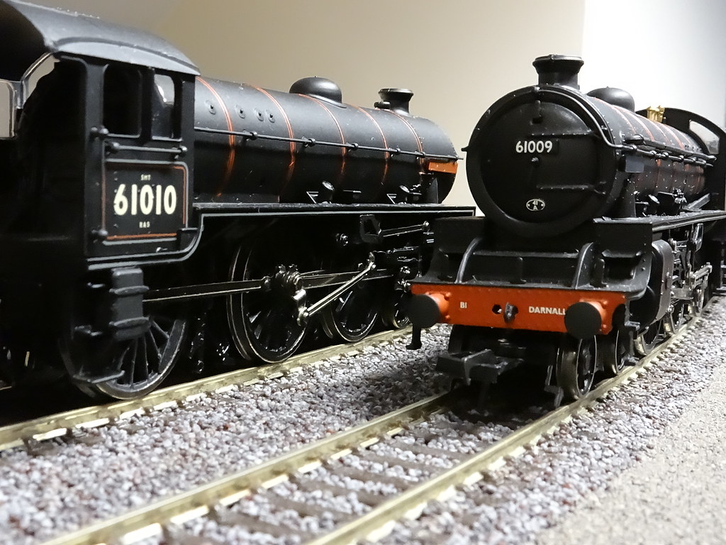
Wheels and axles – Bachmann’s early B1sContinuing my BR(NE) saga I have resurrected a couple of elderly Bachmann B1s that have been quietly slumbering in their boxes.

Bachmann B1s – Widlebeeste and Hartebeeste
There is an issue with these particular early models and mine were not immune! For whatever reason the black plastic wheel centres expand with time and catch on the coupling rods preventing the wheels from freely turning. The affliction does not affect the centre driving wheel and rather puzzlingly it is the rear pair of driving wheels that is most at risk. Fellow modellers report that Bachmann BR standard 4MT models of a similar vintage are also affected.
Bulging rear wheel centre
Another view of the problem.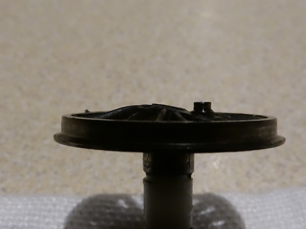
Bulging Plastic
The wheel centre appears to be a type of nylon and can be poked out from behind the wheel using a cocktail stick or very small screw driver. I think it is a push fit into the wheel casting but I cannot be sure.
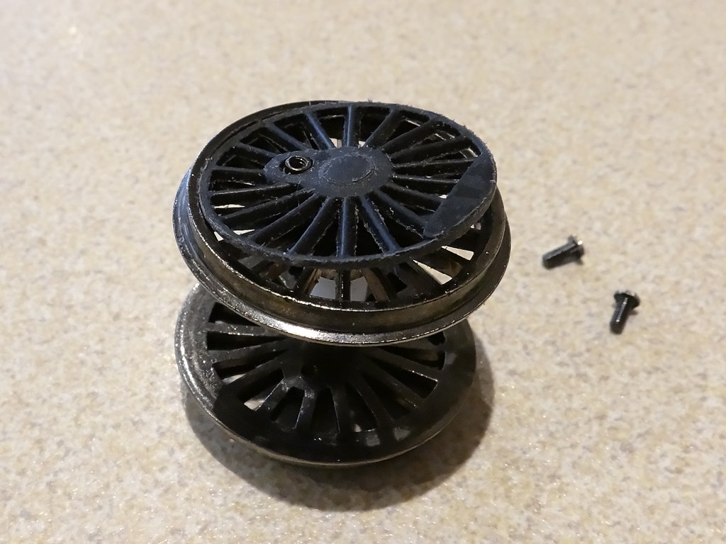
Bachmann B1 rear wheel set
I guess it is possible to remove the wheel centre whilst leaving the wheel set on the engine. However I think it makes life a whole lot simpler to unbolt the connecting rods and lift out the complete wheel set.
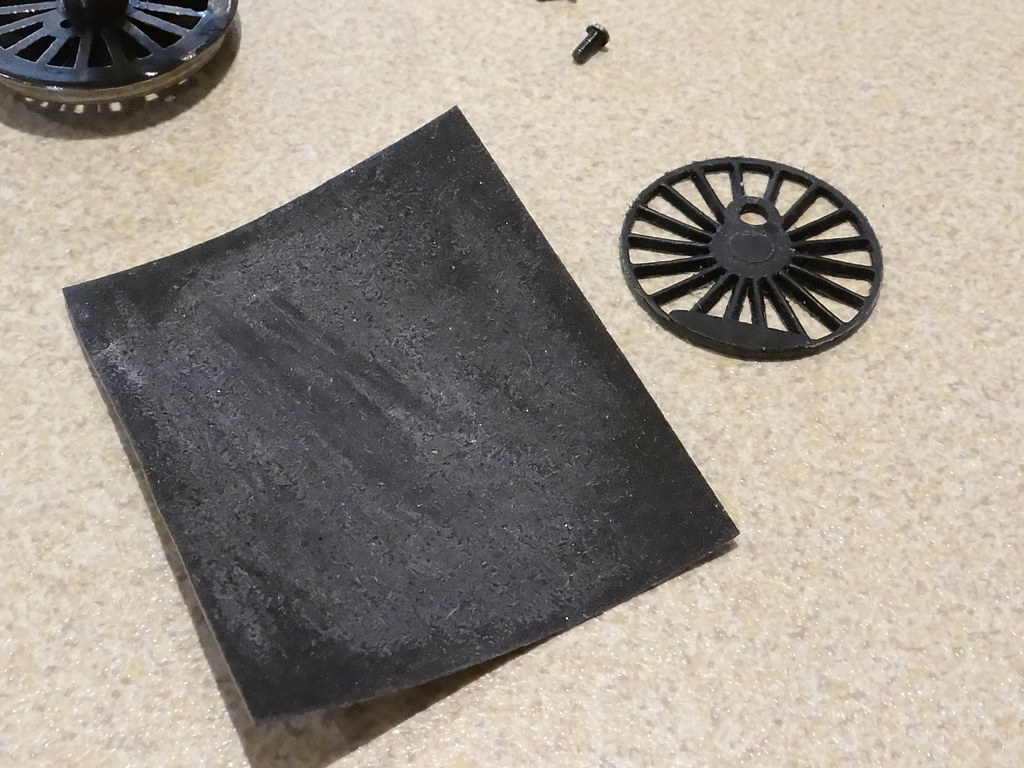
Bachmann B1 plastic wheel centre
The outside edge of the plastic inlay can then be carefully rubbed with 400 grade wet and dry (emery) paper, at the same time gently massaging the spokes back into a flat shape (a bit of warmth seems to help). The ‘nylon’ is tough and it is a slow process to reduce the diameter such that the plastic centre is a snug fit into the cast metal wheel. I have repaired two models and have not used any adhesives to hold the resized wheel centres back in place.
There is a short video here comparing before and after running:
http://youtu.be/BaXy6XUSMoA
Comments from fellow modellers suggest that the wheel centres will continue to expand with time. I have no knowledge of the type of plastic or the chemical mechanism that is causing the expansion, but given that the models are now at least 25 years old I am not expecting a huge increase in expansion over the next couple, or even the next five or more years. We shall have to wait and see!
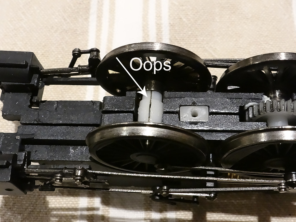
Bachmann A4 Split Axles
The other issue with these old ‘split chassis’ models is the fragile state of the nylon axles. Bachmann refer to the axles as ‘isolators’. They are a force fit onto the ‘squared’ wheel stubs and over time they will crack and break even without any use.
http://youtu.be/YWP0htE-4qM
EBay has lots of listings where old Bachmann models are offered ‘for sale’ – tested working, where subsequently it is obvious that the nylon ‘isolators’ have failed. Even in their broken state the bits of nylon will offer sufficient grip to propel the mechanism backwards and forwards in a straight line. It is only when the wheels are subjected to side forces such as when negotiating a long curve that the wheels will be forced apart – revealing the true nature of the problem.
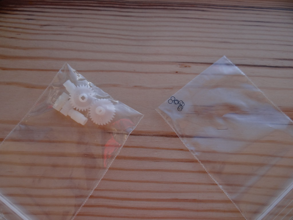
Insulators and Circlips courtesy of Bachmann
Salvation is at hand and sets of isolators are available to purchase direct from Bachmann Technical Department in Leicester.
Thank you for your recent e-mail, we can supply a set of axle isolators (2 plain & 1 geared) for £3.00 and 4 circlips for £1.00 plus £2.00 p&p. The isolators may have different tolerances due to the wear on the tooling. If they are a little slack our technicians use a small amount of glue to keep them in place. If you wish to order please contact us on 01455 245 575 to pay via card, alternatively please send a cheque/postal made payable to Bachmann Europe with your order details, name and address. Please quote SD##### on all correspondence, offices are open 8.30am until 5pm.
Why buy ‘circlips’ you ask? In order to replace the ‘isolators’ I find it best to remove the whole wheel set from the model. On Bachmann split chassis locomotives the valve gear and connecting rods are held by a circlip which slots into a groove on the end of the middle axle. Prising the circlip out of the groove with a pin or fine screw driver allows the valve gear to be disconnected, the connecting rods lifted off and the coupled wheel set lifted out from the chassis. The only problem being that the circlips are very ‘springy’ and if they haven’t shot off the model whilst being first removed, they are likely to disappear out of sight whilst being replaced. Life is too short to spend time searching for missing circlips – you just need a supply of replacements!
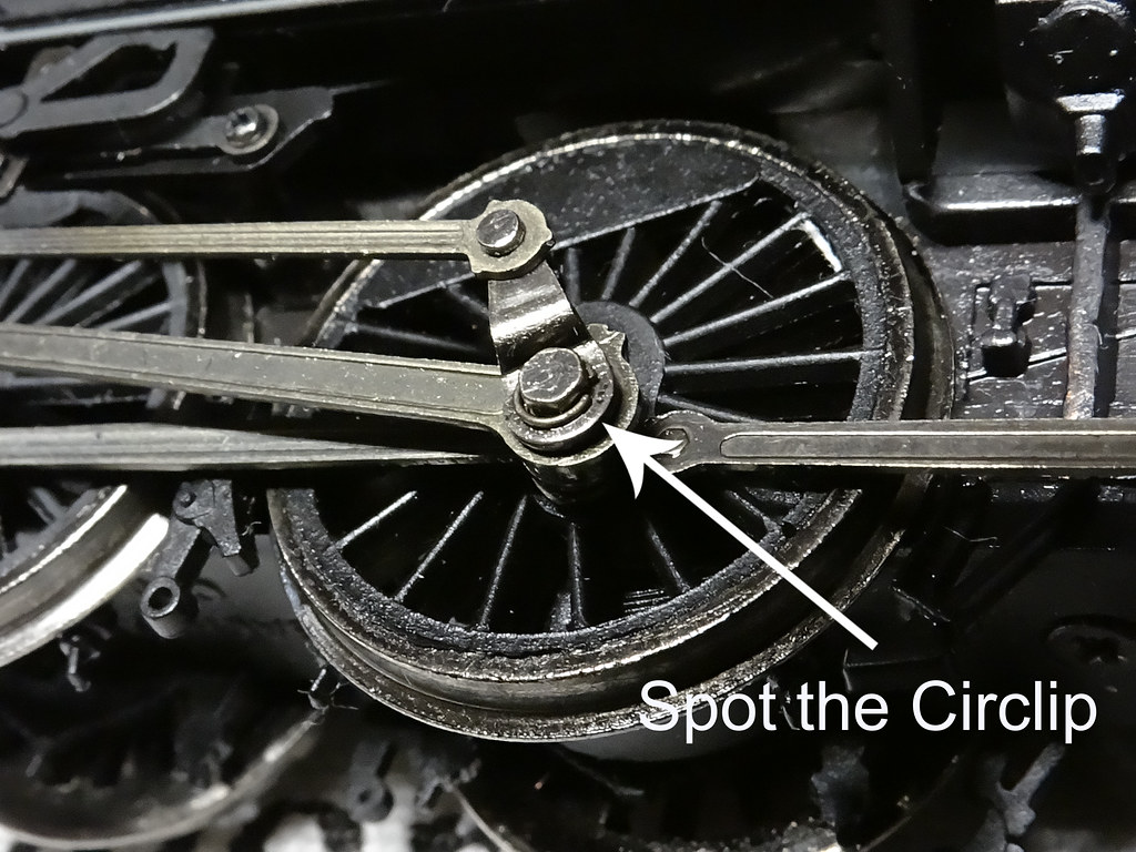
Bachmann B1 – spot the circlip
My experience over a number of years is that the ‘standard’ isolators fit the majority of Bachmann’s split chassis models. One exception is the old Bachmann J72, where the centre gear wheel is offset.
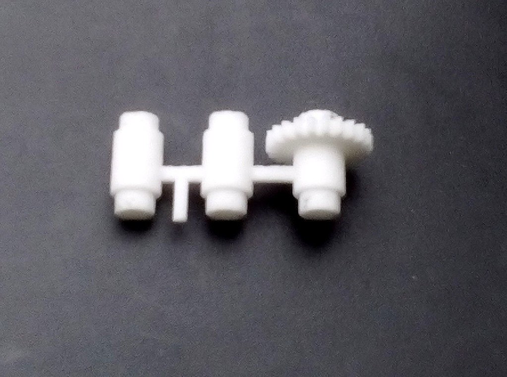
Bachmann J72 Split axles – from an advertisement on eBay
I have not tried to source isolators from Bachmann for the J72 but I have seen 3D printed copies offered ‘for sale’ on eBay. Bachmann isolators are ‘nylon’. I am guessing that 3D printed isolators will not be nylon and may have different mechanical properties.
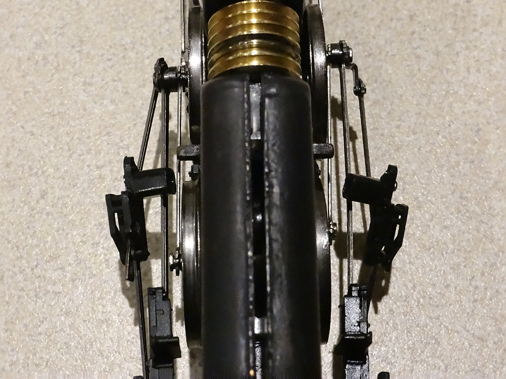
Bachmann B1 – disconnected valve gear
Handling elderly models can be quite stressful! Bits just break and ping off – almost without touching! On one of my B1s the plastic motion brackets supporting the valve gear just fell off the mazak chassis casting. Luckily this is an easy repair - use a drop of Wilkinson’s super glue and push back into place.
http://youtu.be/MKVoG1SsIOI
The proof of the pudding is in the eating, and I now have two nice smooth running models.
Two Elderly Sisters
For the moment I have two good runners which can be bought for a fraction of the price of the latest offerings from Hornby, Bachmann and Dapol – food for thought?
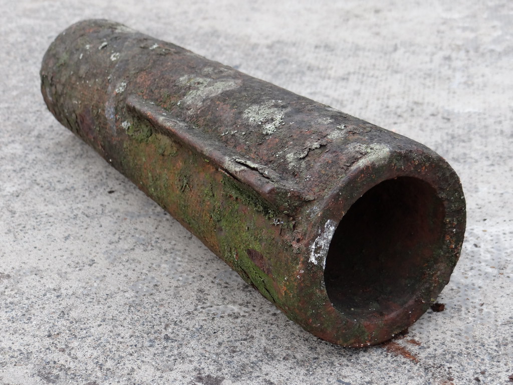
A proper wheel centre - (19thC?) un distorted cast iron, from out of our garden
-
Bachmann Wheel/Axle Faults
Bachmann BR Class 4 woesJust bought this Bachmann 4-6-0 Class 4 Standard Loco.

It appears to be in good condition, and does run. Except it moves with a strange waddling motion, bit like a duck! It's most noticable when looking at it from in front, and the body oscillates from side to side, in time with the rotation of the connecting rods.
Has anyone else had similar experiences? I'm guessing one (or more) of the cranks is out of alignment, but how to tell which, what or where? Or how to fix it?
Thanks!
-
Mark 1 Roof Colour
Wright writes.....6 minutes ago, robertcwp said:Humbrol matt 67 tank grey would probably be a reasonable match for the BSO roof. Interesting how many of the photos show a BSO. Good job Hornby made one.
That's the colour I use the most when painting my carriage roofs, occasionally with a little matt black added....................
Regards,
Tony.
-
Crimson & Cream Paint Matches
Wright writes.....3 hours ago, thegreenhowards said:That looks superb! Can I ask what Hy-cote colour you use for cream. I find Ford Rosso Red works well for crimson, but have yet too find a good match for cream. The ones listed on the online fora are all discontinued.
Andy
Thank you Andy. The cream is Hy Cote Ford 'Sierra Beige' obtained from Sprayster. It looked odd when Just the cream was on the coach but with the crimson it looks well. I've never seen a real crimson and cream coach from 'back in the day' but these two colours go well on the model. They are nothing like any RTR offering from the trade - not that that means a great deal.
")
The Red is Ford Rosso.
-
Hornby HAA Upgrade
Hornby MGR fettling.With the impending arrival of the new version of this wagon, as good as it might well be, I can't afford another 64 to replace my existing stock, so I decided to give my current models a coat of looking at.
There seem to be 3 types of Hornby MGR from my observations, the original wobbly wheeled model, (Mk1 for reference purposes), made in either the UK or China, and the re-tooled rigid chassis, (Mk2), of recent years.
Whilst both have their issues, the Mk1 needs the most doing to it, so I'll start with it. The main failings IMHO are;
1. The body tub.
a. It sits a couple of mm too high in the cradle.
b. The top rim is too thick.
c. The ends of the top rim aren't chamfered.
2. The cradle.
a. The vertical supports at the bottom of the cradle have a horizontal moulding joining them up instead of being in 3 separate pieces.
b. There is a baseplate which helps cause 1a.
c. The end verticals are too thick, but whether this is a worthwhile issue to address is debatable, as they will be somewhat obscured when in a rake and weathered.
3. The chassis.
a. The wobbly wheels and axleguards.
b. 12mm wheels instead of 14mm.
c. No discs on the disc braked wheels.
d. No brake shoes on the non disc braked wheels.
e. Underframe detail, door bangers etc, are moulded in 2D on the solebars instead of inboard.
f. Brake levers and rigging are thick mouldings.
g. Buffers are a work of fiction.
h. No pipework on the bufferbeam.
i. Lamp brackets are moulded blobs.
That basically is a list of things I will be having a bash at improving, other things may be wrong, but there's a limit to how far it's worth going.
The project is a work in progress, so postings might be a bit random, but here are a few pics to be going on with;
I have a liking for jigs, nothing complicated, basically lumps of wood and/or plastic card, but they help make the job a tad more straightforward and easier.
Before and after.
I have a liking for jigs, nothing complicated, basically lumps of wood and/or plastic card, but they help make the job a tad more straightforward and easier.
Chassis holding jig, and a chassis ready for the milling machine, but don't panic, it can be done without one!
For final trimming of the cradle.
For clamping the cradle in the vice for trimming purposes.
Hopefully I've whetted your appetite, and if anyone might be vaguely interested I'll post some step by step information.
Mike.
-
Parcels Vehicles TOPS Descriptions
Modelling a traditional parcels trainNAV: Gangwayed Brake Van 90mph, steam heat only (predominantly Mk1 BG)
NBV: Gangwayed Brake Van 90mph, steam heat only, dedicated Brute workings - code not used after about 1980. Express Parcels written on the side with yellow "Brute Circuit Only" spot. (probably all Mk1 BG but there is a photo of a Gresley BG in this condition but with no code)
NCV: Gangwayed Brake Van 90mph, steam heat only, dedicated for Newspaper traffic (Mk1 BG)
NDV: Gangwayed Brake Van 90mph, steam and electric heating (Mk1 BG)
NEV, NEA, NEX: Gangwayed Brake Van 100mph, steam and electric heating
NFV: Non-Gangwayed Brake Van 90mph, steam heat only (predominantly ex LMS BG)
NGV: 6 wheeled Brake Van (BZ or BGZ). Doubtful if the code was ever carried
NHA: Gangwayed Brake Van special maintenance for 110mph, steam and electric heating (Mk1 BG only)
NIV: General Utility Van, steam piped only (rarely used, possibly on some ex SR GUVs. Seen on ex GW Monster)
NJA, NJV, NJX: General Utility Van, electric wired and steam piped
NKV: General Utility Van, steam piped only, dedicated for Brute traffic
NLV, NLX: General Utility Van, steam and electric heating , dedicated for Newspaper traffic
NMV: GWR Siphon, gangwayed (even those with gangway removed used this code)
NNV: GWR Siphon, gangwayed, dedicated for Newspaper traffic
NOV: Covered Carriage Truck
NPV: Covered Carriage Truck, dedicated to Brute traffic
NQV: Parcels and Miscellaneous Van
NRV: Special Parcels Van (ex "Blue Spot" fish van)
NSV, NSX: Post Office Sorting Van
NTV, NTX: Post Office Stowage Van
NUV, NUX: Post Office Stowage Van with brake compartment
NVV, NVX: Two Tier Car Van
NWV, NWX: Bullion Van
NXV, NXX: General Utility Van, dedicated for Motorail
NYV: Exhibition Van
The third later is for the brakes: V = vacuum, A = air, X = dual braked
Note: there were some NEV vehicles up to about 1979 which were vacuum braked only 100mph BGs. Some were soon given air brakes, others became NDV as they had BR1 bogies. They originally had special maintenance to run at 100mph but they were derated after about 1980.
Most NCV stock had the guards equipment removed and were painted all blue, some also had doors sealed. I say most as the Southern Region allocation kept blue and grey and there may have been others as well.
The NIV code could have been given to some Mk1 GUVs (steam piped only) which did not have Brute chains but the vast majority of them (if not all) received NKV branding from the outset.
An LMS BG which still had gangways (not many after 1978) could have been coded NAV.
From the photos I've seen all the repaints from 1978 onwards carried the new codes. Codes were also added to existing stock from around 1978, possibly late 1977.
The Southern Railway Van C (BY) was allocated code NHV but I doubt any ever carried it as they were all withdrawn by August 1978.
-
Repairs to Mainline Split Chassis
Mainline Manor chassis rebuild (zinc pest)Thought I'd share this in case someone else is mad enough to want to undertake a fairly major repair to their diseased chassis.
have been going through my inventory of models, acquired initially when a lad, so mainly HD/Wrenn based. Towards the end of the 70s/early 80s when I was probably finding other distractions in life, I did acquire some 'modern' motive power - namely an Airfix 14xx, a Mainline 2251 Collet, and a Mainline Manor.
In its day it was revolutionary detail, albeit still suffering from the plastic 'signature' moulding flash atop the boiler/firebox. However, never a brilliant runner, which I probably put down to the missing half kilo of diecast vs. the HD/Wrenn!
However, cutting to now, tried to run the Manor and it would not. No continuity. Dismantled and found that aside needing a clean, the motor contacts to the casting were poor.
Cleaned up and continuity restored. Did notice one chassis half casting looked very 'coarse'.
Tried to run and barely would do so, and any more than 6 inches along it climbed off of the track.
Dismantled more fully to find quartering gone to pot on driven wheels - one wheel/stub axle had turned on the stupid plastic centre shaft. At this point I learned that all split chassis are shyte.
However, more obviously, the rear axle was not square to the chassis, nor was the front. It was plain that the chassis half which looked poorly had effectively 'expanded', so I had a permanent 2ft radius curve built in. Fine for a circular clockwise layout...
Further attempt to dissemble resulted in a piece of chassis literally falling off. Major cracks also visible when underframe removed.
You can see the damage, and also the sizeable difference in spacing of axle holes in the photo.

-
Airfix 14xx Chassis Improvement
Airfix 14xx chassis improvement56 minutes ago, melmerby said:Interesting.
I'm with Jason, there is IMHO nothing basically wrong with these locos and I wonder whether mistreatment and lack of maintenace is where problems have come from.
Definitely neither of those - it is in mint condition in original packaging.
On dismantling one of the faulty plungers the spring had per above clearly lost its temper, and I definitely had a very wobbly driver which in spite of best endeavours with mill vice and so on would not square up. Another plunger case was simply so loose it kept disengaging from the contact strip.
Anyway, to avoid further embarrassment, perhaps I was over-zealous in my condemnation.
However, all said it crawls across points at cogging speed without any faltering. Very pleased and it's a lovely little loco.
I quite like rescuing these early models... ...or perhaps it's just having the time... see...
-
Lima Mark 1 RB Upgrade
Lima 5323W BR(M) Mk.1 RB? Dining carTried the SEF and 50:50, so left out for now.
For those interested, work included:
- Bachmann commonwealth bogies on brass bushes (removing underframe to clear flanges)
- Adding some interior detail (buffet counter, wood panelling, table colour, a few 'customers')
- Adding plasticard propane boxes
- Adding second battery box - made up from scribed plasticard
- Removing all roof water pipes, vents and weld lines
- Removed Lima buffers and added BR ones
- Removed end water pipes
- Adding correct number of welded sections to roof using Archer arcweld transfers
- Adding correct clamshell vents and Ventaxias
- Added end handrails
- Repainted roof
- Stripped Frankenlivery from body (see original pictures at top of post)
- Added strips of 10 thou plasticard rod for window vent draught preventers
- Added steps to solebar
- Primed body/underframe
- Masked sides, blew in underframe and ends in weathered black
- Masked ends/underframe and repainted, relined, named and numbered sides
- Added C1 and solebar transfers
- Satin varnished the lot
Things I know that remain incorrect, some of which I could fix:
- Missing the rectangular kitchen vent - might add later
- Probably need stepboard on bogie below BOTH emergency exits - only did one, but can do other
- Probably should have removed carriage end steps, although not 100% sure whether I might be OK as I haven't added later OLE flashes (is that when steps were removed?)
- Stars for water connection points on solebar?
- Curtains
- I'm sure we can debate the precise positioning of the 'Buffet Restaurant Car' but I have enough examples of variations to be happy enough...
So far it's only cost me a pot of paint and the vents as everything else was around. Some of the transfers we 40 year old Methfix - worked perfectly.
This is what I've ended up with:
-
K's O4 Restoration
Wright writes.....In just over two days.......................
From this............................
To this..........
It's now weathered - I'll post pictures tomorrow, after its dried.
It's clearly K's - no brakes, no lamp brackets, plus several more omissions and inaccuracies. However, I wished to retain the 'spirit' of the thing. And, on a layout, at 'stand-off' scale, let's see tomorrow.
-
Correct Adhesives for DC Kits
My almost correct chop shop, coaches, not even BRYes Charley used to supply wheels with the correct axle length to fit Lima bogies (ie shorter than "normal" ones)
Try using Butanone on the grey plastic bits (including the shiny dmu sides). It doesn't set as quick as plastic weld but it does a better job of holding the parts together.
Baz
-
Hornby 25 Body Height Adjustment
Signaller69's projectsAfter a short break from modelling, I am returning to the various class 24/25 projects. I mentioned previously about the ride height of the Hornby body on the chassis, this is how I now go about lowering it.
As I fit flush glazing I discard the clear plastic glazing unit during dismantling of the loco; it could probably be retained by trimming a couple of mm off the lower edge all round if the lighting is to be retained, otherwise the 2 metal plug units which sit in the glazing strips can be retained within the body (suitably insulated) if required.
The chassis moulding then has the 4 cab door lugs sawn off immediately below the protruding lugs, and the solebar below the door area filed flush. (The bufferbeams were also carefully sawn away as these will also be refitted slightly lower relative to the chassis) as shown on the top chassis in this photo - bottom one is standard Hornby:
At this point the chassis will fit snuggly within the body, and can be assessed for height thus:
I used a couple of dummy bogies for comparitive height checks; as can be seen from the comparitive roof heights, things are looking good.
I added new lugs using some 4mm lengths of 1mm plastic rod (1mm square section should work just as well) fitted level with the top of the cut down chassis lugs:
Which sets the height nicely and holds the body in place:
Next, sorting out the buffer beams (probably....).
-
Ruston's Salt-n-Hairspray Weathering
White Peak Limestone & TarmacadamA very inspirational layout. Can I ask about the "hairspray and salt" weathering you mentioned in regard to the road vehicles in post #42? Not heard of this technique so I'm intrigued as to how it works and what results specifically are achieved?
Cheers,
Martyn.
Hi Martyn,
On the lorry I wanted the bare whitemetal to show through as if it was aluminium sheet bodywork but the same technique is used for rust chips through paintwork. Note that this does not work with enamel paints - not in my experience at least...
First of all you prime the surface if neccesary and then put on a coat of suitable rust colour (I use Tamiya Hull Red)) and leave it to properly dry.
Next you spray the surface with hairspray and sprinke salt on. Use one of those salt grinders if you have one as they are adjustable for the size of grain.
Let the hairspray dry and then airbrush on the top coat.
When that is properly dry, wet the surface - the salt will dissolve and then you can wash it off.
-
BR Crimson/Cream Paint Codes
Wright writes.....20 minutes ago, 60526 said:Crimson/cream, blood/custard? Who's paint did you use for this finish?
Charlie
Cream - Humbrol Acrylic RC 424
Crimson - Humbrol Acrylic RC 423
Varnish - Valejo Mecha Satin (which does brighten the colour slightly)
All sprayed.
Kind regards,
Iain
-
Loco Mechanism Cleaning Technique
Deffo no more second hand4 hours ago, Holmside said:As ever, Johnster’s posts are well worth the trouble of finding and reading carefully. And the comments that he makes in this thread are no exception. I, for one, would , however, be very interested if he would be prepared to describe in more detail what he means by ‘deep cleaning’ and reveal the techniques and materials that he uses to effect this and his maintenance procedures generally. My thanks in anticipation of any reply that he may care to make on this important (in my view, at any rate) subject of getting slow reliable running.
Thank you for your kind comments about my posts! I will happily oblige re 'deep cleaning' Holmside, at the risk of teaching granny to suck eggs.
What I mean by 'deep cleaining' is a complete strip down, throrough clean, and re-assembly of locos, and I do it to new locos as well as second hand because I don't trust the coloured grease lubricant, which attracts crud and can solidify over time, becoming a coagulant rather than a lubricant.
Remove the body, and turn the chassis upside down. Carefully remove the keeper plate, the plastic piece to which the pickups and feed wires to the motor are fixed, gently as the solder joints between the pickup strip and the wires are not designed to be handled and messed about with. Put the small bolts that hold the keeper plate in a lump of Blutac, Plasticene or even chewing gum to stop them making a break for the border or sacrificing themselves to the carpet monster. You can now drop the wheels/axle out, with the motion. Clean the crud and any old lube off the axles, the cog gear, and the motion especially the piston rods, and put them aside safely. An old toothbrush makes an ideal cleaning tool with the aid of a can of spray switch cleaner.
Scrub the old lube and any crud out of the axle channels and from the surfaces of the chassis block in general. Take the motor out if you can, and give the worm a good cleaning, and clean the old lube from the bearings and anywhere else it lingers. Leave the project for a few hours or overnight while the spray can cleaner thoroughly evaporates off, and carefully relubricate with your chosen lubricant. I use a non-mineral fine machine oil recommended by my local Antics as safe with plastics and nylon, applied with a hypodermic syringe. You need to lubricate all the points mentioned in the loco's service sheet that came with it in the box; if you haven't got this you can download it free as a PDF from the manufacturers' website. If you still can't find it, lubricate wherever a surface moves against another surface. Use the mimimum amount of lubricant you can manage; too much will attact crud and defeat the object, a very common thing in 'spares and repairs' 2h locos which have started to run badly and their owners flood them with oil in an attempt to get them running properly again. This might work for a short period, but the crud will overwhelm the mechanics if a fairly short time! If you don't have a hypo, a drop of oil on the end of pin will be fine. Less is more...
Now, carefully re-assemble the loco. If it is an outside cylinder model. take the crankpins of the connecting rod big end off with a nut spinner, or screwdriver on old Triang or Triang Hornby locos. Keep them. and the spacer washer, safe in the lump of whatever you use to keep the small bolts from earlier in, but clean the stuff off the threads when you replace them. This will make it much easier to replace the piston rods in their holes in the cylinder back faces. With the piston rods replaced and the crosshead running correctly on the slide bar(s), you then replace the spacing washer and drop the big end over the crank, and replace the crankpin.
The loco should now run as smoothly as it can. If it doesn't, check that the motion is not binding anywhere, that the coupling and connecting rods are clearing each other and the slide bars, and that you have put the wheels back the right way around. The coupling and connecting rods have little bosses on the tops to represent the oiling points of the real loco, which indicates the right way to put them in, and most current production locos have the cog gear offset from the centre line so it is impossible to get this wrong. Also check that the slide bars are parallel and in the correct position.
Be patient and methodical, and if your eyes start hurting or hands start shaking (mine do, because I'm old and deteriorating), go away and have a cup of tea and a biccy, then come back to it refreshed and relaxed. It is, I contend, good practice, as you get to know the intricacies, strengths, and weaknesses of your locos, and where to start the process of elimination in future fault finding. Each of my locos. like real steam locos, has it's own personality, even with apparently identical models; for example, I have 4 locos running on Bachmann pannier mechanisms, all of which perform in slightly different ways and make slightly different noises.
Slow reliable running is of primary importance to me, as is smooth stopping and starting, and I run a DC layout, so it is a biggish ask of the locos. Current RTR is 'not bad' in this respect but could IMHO be improved and needs all the help it can get! One is demanding the best performance at the lowest voltages and when there is least momentum and proportionally maximum inertia and frictional resistance to movement. Also critical is good tracklaying with the pieces joined smoothly and level to each other, especially turnouts, good track, wheel, and pickup hygiene with access to hidden track being dealt with at the planning stage, and careful pickup adjustment so that the pickup strip bears lightly but firmly and reliably on the rear of the wheel across the full range of sideplay and any vertical play. I find that Bachmann mechs require less hygiene attention less often than Hornby, but a regular regime stays on top of problems. I use some insulfrog turnouts in the interests of wiring simplicity, and only have a problem with a Hornby W4 Peckett on the very long dead frog of a Hornby 3rd/2nd radius curved turnout in the fiddle yard, so have to give her the beans to get over it! The other turnouts are Peco Streamline medium radius insulfrogs, with small radius for the loco release shunt. That apart, my running is pretty good, with a combination of Bachmann pannier, 56x, 45xx/4575, standard 3MT tank, and 94xx mechs, and Hornby W4 and 5101, with a Silurian era Airfix large prairie getting an occasional run as well. I am in the process of building a 1938 Collett 31xx with another ex Airfix large chassis from the 'might come in handy one day' box, rewheeled.
My slow running is pretty good, though to get the absolute best out of each loco, one must develop an individual driving technique for it. My required standard is that all the locos can pull or propel all the stock in any combination to or from any point on the layout in any combination at a scale 15mph, and I haven't quite achieved this but am close enough for my normal running purposes. I have eliminated traction tyres which I consider to be satan's nasal effusions, and plastic wheels, and taken some trouble to ensure coupling and buffer reliability and a standard height above the railhead, not as easy a quest as it should be! All stock and bogies have to pass the 'mirror test'. I must be able to place the item upright on a glass surface and be unable to rock it, with the flanges visibly touching their own reflection. Use Lego bricks to establish squareness and level of wagon kits (and buildings, and anything else where this is relevant). Lego shop will sell you a plastic pot of as many of any type you want for £6, keep putting them in until you can't close the lid, handy for all sorts of things...
Another point is ballasting of locos. My ideal is to use collapsed star material or unobtainium, crammed in to the maximum possible extent above the driven axles and balanced in the smokebox and bunker. This is harder in some locos than others, and I sometimes remove the DCC 'ready' board and chip to get a little more in. I use a combination of 'Liquid Lead' and Milliput with bits of scrap metal in lieu of unobtainium. I'm told that overballasting can cause excessive wear in mechanisms, but I've never had an issue with this, and the result has always, without exception, been an improvement in pickup and running. Leave about 2mm around the motor for ventilation and cooling, though.
I try to establish a standard of 10g minimum axle loading for wagons, difficult in the case of unloaded conflats, lowfits, and plastic kit empty opens. This is important for reliable propelling, and advised for long trains on setrack curves. Keep the ballast, and hence the centre of gravity, as low as possible; beneath the solebar if you can but it is sometimes difficult to keep it out of sight on RTR wagons. Lowfits/Loriots are next to impossible in this sense, and the reason I don't have any; they would have been pretty rare in my supposed location anyway!
-
Soldering Techniques
Wright writes.....17 hours ago, polybear said:Hi Iain,
Stunning as always; I'm always amazed at just how neat and tidy your solder joints are - could you share some of your secrets regarding soldering so neatly and cleaning up as well please?
Many thanks
Brian
Hi Brian,
Thank you for your kind words. I don’t really have any soldering secrets and some of the stuff I do can be quite a mess!
My first foray into soldering was as a teenager trying to solder the side of a whitemetal tender to its end casting using dad’s bog-standard soldering iron and tinman’s solder; it did not end well! It was only wanting to put a Comet Models chassis under an old Airfix 4MT Mogul that caused me to have another go. To get me on the right track I used the examples and ideas put forward by Iain Rice in his book on etched loco construction which has many concepts, tips and photographs. Over a couple of years and a few learning experiences (disasters) I found I was able to put a reliable chassis together, and to a reasonable standard.
Today, I have a cheap Chinese temperature-controlled soldering station (a YiHua 937D), the LED display states it works from 200 to 450 degrees. I have no idea how accurate that is. I have three chisel shaped bits (all Hakko): 1.1mm, 2mm and 3mm. Which in simple terms are for small, medium or big solder tasks! I make my own flux at about 10-12% strength, if my maths is accurate.
I prefer small soldering iron tips to large, as it’s a good control measure of how much solder you put into a job. I work on the premise it’s easier to add a little more solder, than it is to remove it. By using a large tip, you invariably introduce a lot of solder. So my default is to use the smallest tip I can get away with.
For soldering brass, I use 145 degree solder (sadly from Eileen’s) in a coil. I don’t like the blocks of solder as its difficult to control the amount of solder you can melt off. I know I can cut/shave bits off but that’s just inefficient. I apply the tip of the hot iron to the end of the coil, melt off the amount I need, and then apply the tip with the solder to the job. If I get too much solder on the tip, I wipe it off and try again.
I use the 1.1mm bit the most, probably 80% of the time with the temperature set somewhere between 365 and 385, depending on the size of the job. For something like a Comet Models carriage table its 365:
For a door stop, door hinge or drop light in a carriage side its 385:
The other side:
If the iron is too cold the solder won’t make the join quickly and I find I’m lingering, if it’s too hot it will quickly discolour the brass (a pinky red colour), which ever happens, I’ll tweak the temperature by maybe 10 degrees the other way. In most instances the discolouration will wash off.
I apply flux with an old, small paintbrush – Iain Rice recommended sloshing on the flux, I don’t do that, I try and brush/dab it carefully as wherever the flux is, the solder will flow. I always try and solder from the inside. I struggle to sweat things together so will invariably drill a hole in one piece, lay the other piece (that I want to attached to it) over it and solder through the hole – so for something like a ventilator on a carriage door, I drill a hole in the carriage door, place the ventilator over the hole, secure it with a bit of masking tape and solder from the carriage inside, through the drilled hole. To stop flux splattering I may cut and use a piece of paper as a shield or barrier to protect other surfaces.
To join a carriage end to a side, it’s the 3mm bit with lots of solder on it, the iron is set to 400 apply a goodly amount of flux, applying the iron and moving it along the join (that keeps the heat localised and reduces the chance of dislodging already soldered items), and out quickly. If the interface between the two is tight before soldering, the solder is less likely to flow outside the join.
For whitemetal I set the station to 200 degrees and do most of the above. If I’m soldering brass to whitemetal, I coat the brass with a thin layer of 145 solder and use low melt for the join. I have a separate 2mm bit for whitemetal work. I’ve never found low melt solder flows on whitemetal like 145 does on brass, so my whitemetal joins are more like small ‘spot welds’. My whitemetal soldering experience is quite limited, it’s still work in progress.
I find soldering quick and easy if the bit is clean and the brass (or whitemetal) is clean. The Hakko tips need little care other than a wipe on a damp sponge between every application. The 'tinned tip' should be nice and shiny , if it has black deposits on it (burnt stuff?) I carefully scrape that off with scalpel blade and wipe it again. And I change the sponge regularly as they soon get dirty. I’ve never used one of those wire cleaner things. I have some ‘Tip Tinner’ and will occasionally re-tin the tip.
Not every day is a good soldering day, if I’m struggling with the first application and I can’t get the solder to stay on the tip of the iron I usually switch it all off and walkaway and come back later, then miraculously things seem to be fine!! I also solder in small sessions.
For cleaning I use Jif/Cif cream cleaner and scrub with a toothbrush. If a new, but old, brass kit is tarnished I will scrub it before I take the items off a fret. If the tarnishing is really heavy, I might use a very fine ‘wet ‘n’ dry’ type paper to mechanically clean the brass. I clean what I have soldered after almost every soldering session to remove the flux residue. If the cream cleaner goes a dirty grey, it will probably get a second clean. It’s also a good way of telling how secure the solder join is. Everything gets a really good rinse off.
Sorry if the above is a bit of a ramble, it started off as a few dot points but I felt that lacked context or explanation. It is what I do, it’s not the only way and I appreciate it’s not what some others might do either, but it works for me. Who knows it might work for someone else too.
Otherwise I wish everyone a safe and happy Christmas.
Kind regards,
Iain
-
Tony's Loco Building Guide
Wright writes.....Just now, thegreenhowards said:I agree, particularly with outside cylinders. Also brake gear touching wheels on a live chassis.
How long do you want the list to be Andy?
Seriously, what I've found with many duff runners is that at no point during the construction was 'due process' followed. I'll explain.........
1. The frames must be assembled dead square and true using a jig. The bearings should be inserted at this stage, with any inner axle bearings being soldered in place the tiniest bit higher than the outer ones (I'm speaking of rigid frames here). The trick is to broach out the inner bearing holes just a bit more than a snug fit, meaning one can raise the top hats slightly higher up than the rest when soldering in place. Tap any holes in spacers to take the shouldered screws for retaining bogies/ponies. If it's a flat spacer, solder an 8BA nut to its top and tap that to remove excess solder. Cut off any excess bearing material from the inside of the top-hats on the driven bearings, filing them flush with the inside of the frames - for OO; for EM, often just a small amount needs removing.
2. The drivers should be fitted to their axles (Markits in my case) and fitted to the frames, but only after I've passed a one eight taper reamer through all the bearings. If the frames are true, then all the outer wheels should sit fair and square on a piece of mirror glass. If not (and this heresy to a real engineer!), twist the frames ever so slightly until all is true.
3. Take the drivers off again, then solder the brake cross rods in place. Check that the drivers' flanges don't catch on those rods. Crankpins should be fixed at this stage and held in place with Loctite.
4. Fix the pick-up pads securely in place with epoxy.
5. Assemble the motor/gearbox (or use a ready-made type) so that everything is absolutely sweet. Prior to fitting the motor, check that it runs perfectly; it's incredibly frustrating when trying to find a tight spot, to learn that the motor itself is the cause! Place the driven axle through the gearbox bushes and tighten up the gearwheel's grubscrew (Markits now produce a slotted axle). Check that the driven wheels rotate freely, then check again with the whole assembly in its place in the frames (this requires drivers being put on to and taken off their axles several times - a poor idea with friction-fit wheels. Indeed, I know of some P4 modellers who'll set up their frames with Markits wheels and axles, before finally fitting the drivers of their choice). Oil nothing at this stage.
6. Paint any areas of the frames behind the drivers (I use a sable and and enamels), allow to dry, then re-fit all the drivers for (hopefully) the last time, taking out any excessive sideplay with spacing washers.
7. Fit the pick-ups (.45mm nickel silver wire in my case) and take the wires to the motor brushes. For a live chassis, one side can both act as a return and also a stay to prevent the motor clattering around inside the body under load.
8. Test that all the pick-ups are working. If they are, and the drive is on an inner axle (the centre one on a six-coupled), then that pair of drivers should rotate freely on level track (their being a fag-paper thickness higher that the rest). If the drive is on the rear axle, then the chassis should shuffle along. Oil the axles in their bearings at this stage.
9. If coupling rods are laminated, hold them in place with cocktail sticks while soldering. If they're articulated, I solder them solid. Broach out any bearing holes to give a snug fit on the crankpins. Hold the rods in place with plastic sleeving, and test the running chassis. With luck, it shouldn't bind. If there is binding (it'll be at 3 o'clock or 9 o'clock one one or both sides), broach the appropriate holes until there's no binding. Just letting a chassis, plus rods, roll down an inclined plain is not a good enough test; it must be driven. When all is sweet, solder on the crankpin retaining washers, using a piece of instruction paper as a spacer and a barrier to solder, tearing it away once the job is done. Take off any excess crankpin with cutters and file, remembering to leave those with valve gear attached full-length. Oil at this stage, and run-in the chassis on a rolling road. I'm not a fan of Markits De-Luxe crankpins.
10. Fix any brakes at this stage - brake rodding fitted at an early stages prevents pick-up adjustment.
11. Only make any cylinders/valve gear/motion after the body is completed, though bogies/ponies can be made/fitted at an early stage.
The making of outside valve gear would take at least another ten steps to describe; so, for another day?
I'm bound to have forgotten something, but the above are my usual steps. Those who make compensated/sprung chassis, or use the 'American' system of pick-ups may happily disregard anything I've noted.
Regards,
Tony.
-
Tony Wright's Coupling System
Wright writes.....7 hours ago, Andy R said:Tony;
Now back home in NZ. Reflecting on my visit to your wonderful layout I have a query or two:
1. Is it possible for you to post a couple of photos of the simple coach coupler system you use- between coaches and between coach and loco? They work so well and get rid of those ghastly rtr ones.
2. Do you have any advice as to how one puts a ‘value’ on kit built locos that can be put up for sale? How do you arrive at a fair price? Other group members may have a view also?
Cheers- Andy R
NZ
Good morning Andy,
Glad you got back safely.
My couplings? They really are simple, cheap and effective...............
Seen without the 30Amp fusewire additional pipes.
Now with the addition of the pipes (only attached to the towing vehicle).
In crude (and cruel) close-up. Just two lengths of PCB sleeper strip, glued underneath, then the goalpost and hook made from .45 mm brass or nickel silver wire, with 30 Amp fusewire for the train-heating/vacuum brake conduits, all soldered solidly together.
Visually...........
I think my couplings 'work'.
They certainly work 'physically' inasmuch as they pull off the headstock (like the real thing) and not the bogies, can be propelled with equal ease as being towed and never come uncoupled. Granted, they're not even semi-automatic, but since LB's rakes in the main are dedicated, there's no need for coupling/uncoupling on the layout. If that's required (for the pick-ups), I use Sprat & Winkles........
Which work just fine.
Ends of dedicated rakes..............
Look even more like the real things because they only need to run one way. (Note the tail lamps - no trains run on LB without appropriate lamps, front and rear).
I use the same coupling system on good trains which run in dedicated sets as well...........
I'm not claiming that these are 'realistic' (though they're a lot more than tension-locks), but I can't be doing with faffing about with three-links or screw shackles!
Your next question answered shortly................
Regards,
Tony.
-
Ratio Midland Coach Areas of Operation
Wright writes.....13 hours ago, Northmoor said:What livery would these coaches have worn post 1948 and how long did they survive in the BR era?
2 hours ago, Tony Wright said:Where was their final sphere of operation, please?
The Ratio Midland Suburban carriages represent 48 ft, 8 ft 6 in wide stock on 10 ft wheelbase bogies, built first in 1903 for the Manchester South District services, where the ran in nine-coach sets of four firsts, three thirds, and two 6-compartment brake thirds. These sets were withdrawn between 1938 and 1947. More were built in 1908/9 for the Birmingham District, where they ran in 6-coach sets, BT (6 compt) / T / F / F / T / BT (6 compt) and in two sorts of 4-coach sets, BT (6 compt) / F / T / BT (6 compt) and BT (4 compt) / C / T / BT (4 compt), the latter being used on the Gloucestershire loop line to Evesham and Ashchurch. Many of these carriages were transferred to the LT&S section, they were mostly withdrawn in the late 40s / early 50s. There were similar carriages built for the Sheffield District (with two four-coach sets for the Worth Valley) in 1914, but with 8 ft wheelbase bogies; a good number of these lasted until 1957/8. Some of the brake thirds (4 compt) were converted to motor train operation with the usual large windows in the driver's end, one being photographed on the Mansfield and Southwell service in 1955. That carriage at least was electrically-lit.
There were many similar carriages built 9 ft wide and 50 ft or 48 ft long, as sets for the London and Nottingham areas, which also survived to the late 50s. All these sets were close-coupled with short buffers except at the brake ends, so to be used as loose carriages would have to have had long buffers fitted at the non-brake ends. It seems unlikely that this happened; when transferred to the LT&S section they continued to work in sets with other short-buffered carriages.
So as far as i can work out, if one sticks strictly to the types represented by the Ratio kits, the final sphere of operation, in the 1950s, would be either the Tilbury section or, with 8 ft bogies, the ex-Midland lines in Notts / Derbys / S. Yorks. If one allows more latitude, similar sets also remained at work in the London area. It does seem that sets surviving into the mid-50s were painted BR crimson.
Sorry for all that, more than you wanted to know, I know, but the Birmingham Area sets are a particular hobby-horse of mine!
-
Assembling Valvegear by T. Wright
Wright writes.....Assembling valve gear?
I don't use rivets - they end up either too tight or too loose.
What do I use? Brass lace pins (sold at haberdashery shops) and solder. Put a piece of instruction paper between the components to be joined and solder the pin to the rear component. Nip off, file clean and then remove the paper. A perfect working clearance. After assembling at least 300 sets of outside valve gear, I think I've worked out which method suits me.
Examples tomorrow.


")


.jpg.fff5097b8563d63fed23519e2cffa04a.jpg)
.jpg.80639177e14c69bc06083ec7ac37dc79.jpg)


