jdb82
-
Posts
485 -
Joined
-
Last visited


jdb82's Achievements
1.2k
Reputation
Bookmarks
-
Weathering
PETES WORKBENCH. Scratch building a LSWR 0395 class, long term project1 hour ago, jdb82 said:Nice work with the weathering! What do you use for your weathering? Powders, dry brush, air brush? Or a combination of all of the above?!
I generally don't use the airbrush for weathering. To me it always looks like it's been airbrushed. On these I used a watery acrylic paint of a muddy brown with a hint of black. Painted on left for a few minutes then cleaned off with dry or moist cotton buds depending on how it was drying. Always in downwards direction. Then finished with a rust coloured powder, on the iron bits. I use a stiff brush to apply this and a bigger one to try and work it of the area's I don't want it.
-
Gladiator LNER/BR J6
Gladiator LNER/BR J6Today has been a brilliant day on quite a few fronts but the main one being that I successfully soldered the crank axle up without any issues.
I followed advice given to me by fellow modeller Nick Dunhill, which was to use Bakers Fluid as the flux to solder to the steel axle, to replace the piece of steel rod provided to line up the cranks and eccentric with a length of similar diameter brass rod which being more flexible allows the cranks and eccentrics to be squashed tighter together and positioned better. And finally, to wrap wet tissue around the eccentric sheaves to stop the soldered end coming adrift with the heat.
It couldn't have gone any smoother, I spent some time making sure they were all lined up correctly and orientated against one of the flat edges of the axle end. I grip the other end in a biggish pin vice applied the Bakers fluids from a bulb type dropper and some short lengths of 180 solder curled slightly around the axle either side of the cranks then gently applied heat with the microflame until the solder flashed. While it was cooling I couldn't resist moving the eccentrics slightly to make sure that they hadn't become solid.
All was well Phew!!!

Next job is clean them up and then before cutting out the section of axle I think that I am going to drill and pin the cranks. I know that Nick doesn't bother as they aren't under any real load but I think that I will be belt and braces for this my first go.
-
Weathering with ink and weathering powders - O Gauge Ruston 48DS
Weathering with ink and weathering powders - O Gauge Ruston 48DSSteve
currently I am using Rotring ink for Black and a variety of Windsor and Newton drawing inks ( and others) for browns, greens etc.
I buy them at my local artist shop.
best regards
Barry
-
A Broad Gauge Adventure - Nick Dunhill's Workbench
A Broad Gauge Adventure - Nick Dunhill's WorkbenchA quick catch up. I have done a fair bit to the valve gear this week. As mentioned above I have ordered a large batch of eccentric sheaves to replace the LGM castings. The cast ones have an OD of 9.8 mm and the eccentric strap ID is 9.0 mm. Therefore the eccentrics and/or straps need a lot of fettling to get a good fit, and it has to be done by hand so customer has to reconcile a big labour cost. The LGM ones have a flange cast on which makes them too thick so if you use the cast LGM valve guide the outer eccentric rods have to be dog-legged slightly to bring them into alignment with the sheaves. I ordered 100 which is enough for 25 two cylinder locos (in the last 12 months I've made 6 sets!) I'll have a few sets to spare if anyone wants some.
So the week has been spent fettling rods and building cylinder bottoms and drain cocks and a few other odds and ends.
The way the inside motion is arranged in the loco results in eccentric rods that are near the maximum length for the castings. I took the approximate length from the dummy set in the Scorpio kit and, with a bit of advice from my dad (engineer, retired) they seem to be about right. I'll know when the eccentric sheaves arrive, but you can work it out from the throw.......I hope.
Brakes next week, well on at least one loco. The pic of 1207 I have shows it running with no brakes on the loco .
-
Ruston's Industrial locomotive and wagon workshop thread.
Ruston's Industrial locomotive and wagon workshop thread.Sorry to hear that David - I use the Technobots Mod 0.5 black plastic bevel gears where I can (my narrow gauge locos need the smaller 0.3 brass ones on 2mm axles). If you want to repeat the experiment let me know and I'll drill you out one 1/8" and one 3mm.
Giles
-
New feature - Bookmarks
New feature - BookmarksI have installed a new feature for members; a capacity to bookmark content within RMweb.
From the dropdown menu accessed by clicking on your username at the top right of the screen you will see a My Bookmarks link. From here you can create your own sub-folders for bookmarks e.g. modelling reference, prototype reference etc. You can then access any bookmarked content from here.
At the bottom of each post (please note you can only Bookmark posts, not pages) there is a Bookmark link - clicking on that adds it to your bookmarks and if you have created any sub-folders you can choose where to save it to. You can choose for your bookmarks to be public or private - I would suggest private (in fact if I could have removed the public option I would have). Bookmarks can be removed at the relevant post or within My Bookmarks.
This is a neat way of saving material for later reference without being reliant upon your browser (and saving space in your browser's bookmarker.
-
Charlie Strong Metals (and Watery Lane Sidings)
Charlie Strong Metals (and Watery Lane Sidings)2 hours ago, 37114 said:Hi Dave, I have not heard of the graphite trick before, what do you use please (I presume something more sophisticated than a "HG" pencil)?
Hi Rob,
You do surprise me! I thought you would have known about it. I've been using it for years now. I had problems with getting things to run reliably way back when I built Bury, Thorn & Sons. So much that I was thinking of giving up on it and on building kits. I thought it must be something I was doing wrong and when I visited @Giles to buy a loco from him, he told me about it. I tried it and it transformed the running of my locos and I've used it ever since.
I use this stick, bought from an artists' shop. It cost just £1.50 and as you can see from the marks on the side and the wear on the pointy bit, it's had some use but after 7 or 8 years, it's going to outlast me at that rate of wear! I don't know about the hardness or anything as I simply asked for a graphite stick and this is what they gave me.
It did have something about the manufacturer and possibly the hardness but it has since had the paper wrapper taken off to allow the flats of the sides to be used in the Fiddle Yard. I use the point to do the inset track so as not to get graphite on the setts and the flat end for most of the rest.
I've built about 4 layouts since BT&S and what I now do is to run the stick over every bit of track after laying it but before paint and ballast have been applied. Paint and glue won't stick to the graphite and so it's very easy to clean the excess off. I clean the mess off using an old-fashioned Peco track rubber and then go over all of the rail tops again with the graphite stick. I'm not going to even pretend to know the science behind it (there are threads on here about it, where at least one person says the science says that graphite doesn't work) but in my experience of using it for 7 or 8 years, it seems to prevent the nickel silver track from oxidising and also conducts electricity itself.
I use CSM/WL regularly but the CVMR, which lives in the garage, doesn't get used anything like as often but I can go to it and start running trains immediately, even if nothing has run for months. I don't need to clean the track and I have never had to clean the wheels on locos or rolling stock. I used graphite on White Peak and over 3 days of exhibiting the track didn't need to be cleaned and everything ran faultlessly. That was on plain DC, too.
I never clean the track these days and simply run the stick over the rail tops every couple of months. I don't know how much graphite it deposits but there's no sign of a build up. It also has the side-effect of hiding that bright nickel silver colour of the rails and I think that graphited rails look more realistic. The best £1.50 I ever spent.
-
Neilson Box Tanks works list with Photos
Neilson Tank Engines Boxy and Not BoxyOn 03/11/2021 at 15:15, Barclay said:I had Narrow Planet produce the works plates a few years ago !
Ah missed these recent posts but as it happens Silver Tay Models produced a set of custom G3 scale plates for me earlier this year.
The West Somerset PDF drawing was the starting point but enhanced the design through an old Neilson advert, a kindly forwarded photo of an old mineral tender design and the book 'British Locomotive Builders' Plates : A Pictorial Guide' (sadly it lacked an example of the unusual long type but still handy for filling in some details).
Some are repeats from the previous pages but as I'm posting here's a condensed list of Neilsons to try and make some sense of their changing prototypes.
*I own no copyright, below is just for informative purposes and to preserve some images from expired links. Thanks also to those who found some of these obscurities as well as dispel some falsely identified members.
*Engines are standard gauge unless stated otherwise.
Works No.47
Drivers 3' 0"
Cylinders 10"x18"
Boiler 110psi (seems high to me)
Dalmellington Iron Company No.1 was delivered from Neilson & Mitchell in 1851. Although soon outclassed this little engine survived in service until 1882 despite a boiler explosion in 68! Full story can be found in the book 'Dalmellington Iron Company: Its Engines and Men'.
Works Nos. 49 &50
It's not clear what these were but it's said Troon Harbour/Kilmarnock & Troon owned two 4-wheeled tanked engines in 1851. Given no evidence of piano nor round saddle tanks have come to light for the early years I'm inclined to believe these and the rest below were box variants.
Works No.65
Dalmellington Iron Company No.2 was built in 1854 but sadly not photographed it seems. With her tank extending over the chimney it was said to be similar to their later No.5 (see Works No.1129 below), but was a bad steamer throughout its life and taken out of service for rebuilding in 1879. Ultimately this did not progress and it was left in parts with its replacement saddle surviving into the late 20s. Again David L Smith's book gives more detail.
Work Nos.81 & 82
Drivers 3' 6" (8 spoke).
Cylinders 11"x 18"
Boiler 90psi 10ft long
Firebox 3' 6" long
Weight 12 tonsCost of both engines along with the new wagons was £5047 19s 9d.
Miner & Smelter were delivered for the 4ft Redruth & Chasewater Railway in November 1854 but proved to be ruff on the track. To cure their short wheelbase and rear overhang 2' 6" trailing wheels were added in winter 56 complete with brake blocks as Neilson's handbrake applied only on the rear driving wheels was not adequate on the line's gradients.
Maintenance was difficult with only two engines so a third and more powerful one arrived in 59 (see No.540 below).
In 1870 Smelter was re-boilered and this overhaul seems to have left her much as she was prior,
*Said to of been taken in August 1872. The patched tank is showing its age though there is no evidence of a brake set on the trailing wheels.
while Miner was more ambitiously rebuilt the year prior into a heavier 0-6-0ST to bring her near in line with Spitfire.
Cylinders 12"x18"
Boiler pressure 120psi
*Beside said boiler an old school Haycock firebox was fitted along with new cab sides, a new box tank, worm gear drive (the same set up applied to Spitfire that could cope with wet sand) and a rear coal bunker. On top of that was a spectacle plate, but it proved unpopular with the crews and was soon removed. It's possible the rear frames were altered again to accept the rear drivers and the length extension, but imagine the frames were completely replaced. Altogether little of the original engine appears to be left and the large bunker plates proudly stated 'Redruth & Chasewater Railway Company - Manufactured at Devoran Works 1869'.
*Not sure where Iain Rice got such a specific wheelbase from nor why he has quoted 3' 9" wheels, but the extra drivers do match the style of the original 8 'T' spoke cast wheels.
As the railway's fortunes declined so did loco and track maintenance and the un-rebuilt Smelter became an emergency use engine while Miner became the mainstay and in 1915 had the 'honour' of pulling the final trains lifting up the track.
??
Said to be taken in 1855, possibly at the Neilson works.
http://www.douglas-self.com/MUSEUM/LOCOLOCO/onecylinder/onecylinder.htm
??
Details are lacking but the Monkland Railway was said to of owned an 0-4-0ST in 1855 and this later became North British Railways No.282.
Works Nos.344, 345, 350, 351, 367 & 368
Cylinders 12"x18"
The Ebbw Vale Company ordered six box tanks from Neilson in 1855 and these were built and presumably delivered in pairs that year. Details on these six are sketchy at best,
* This photo doesn't show it but the settings on another copy printed in an old article makes a toolbox close to the tall chimney visible.
but one was named GEN. WILLIAMS,
*Taken after the 11th of September 1878 underground explosion.
*Between c1893-5, Victoria works, outside of the Victoria blast furnaces. Now an ogee tank with a few other changes.
another Newport,
*1896 at Watchet. Despite being rebuilt in 1895 this engine appears to have been scrapped in 1900.
and another who's name I've not been able to deduce. It's something like 'MEMBE COMJ' which is nonsensical and not a match of any of the recorded names, but the first three letters I'm reasonably sure about being correct.
*The quality of this upload is very poor but while it only makes up a small potion of it a large photo hanging in the Ebbw Vale Works Museum is worth a look at if you get the chance to visit. This rebuild obviously has a round tank like Newport, but otherwise is similar to ogee form Gen Williams in terms of retaining the diagonal dumb buffers and (bar the rear height extension) the style of the bunker.
*Looking at the Newport photo it can be seen the 'cab' area is a little different to the other two. This might simply be down to the rebuilding, but it might also be the three pairs were not cosmetically identical when new and this would explain the coal bunkers being curved and the lack of flaring at the rear. With such limited material it's down to a fair bit of guess work I'm afraid.
Works No.349
This engine falls within the six above but the 0-4-0ST owned by Colvilles LTD of Calderbank Ironworks near Airdrie was said to be an inside cylinder type so there's some doubt about it being a possible box tank.
Works No.354
This 0-4-0ST also falls with the above six but for simplicity will cover it and the next two separately. It was owned by Gartsherrie Ironworks in Coatbridge and like so many entrees here information is scarce so hard to confirm or dismiss it being a box tank.
Works No.359
One of the single cylinder boxes. Built in 55 for Colvilles LTD, Calderbank Ironworks near Airdrie. I have it listed as standard gauge so that would seem to rule it out being the photographed engine several above.
Works No.366
Built in 1855 this 0-4-0ST went to the Baileys' Line (later Brynmawr and Nantyglo Mineral Branch) near Ebbw Vale.
Works No.369
Another mysterious pug for the Baileys' Line (later Brynmawr and Nantyglo Mineral Branch), near Ebbw Vale. This one is listed as being built in 1855.
Works No.370
Cost £1055 0s (£1065 with delivery expenses)
Drivers 3' 6"
Cylinders 12"x18"
Boiler Pressure 60lbs (seems low but suggested this was raised to around 90lbs in later days)
Weight 13tons (In working order)
Length over buffers 21' 6"Wheelbase 5' 0"
Due to tying overlaps with the Ebbw Vale Company the West Somerset Mineral Railway ordered a box tank from Neilson in the latter half of 1856 to assist with construction of the network. It arrived in November, though there were some differences to the six strong batch design such as the tank pattern.
*1889 'The Box' seen at the top of the Brendon Hill incline.
By December 96 the loco was worn out and replaced by one of the Ebbw Vale six. After a period of storage it went to Ebbw Vale and was scrapped in 97.
Works No.371
Cylinder arrangement is unstated but an 0-4-0ST? was possibly acquired by Colvilles LTD for Calderbank Ironworks near Airdrie in 56.
Works No.373
Another for Calderbank Ironworks near Airdrie in 56. This box is said to have been a single cylinder so it's quite possible Works No.371 was also.
Works No.374
Another for Gartsherrie Ironworks, Coatbridge. The year 1859 instead of 1856 is listed for this outside cylinder, but unless acquired secondhand or a long held onto stock engine is erroneous.
Works Nos. 376 & 377
More single cylinder 0-4-0STs for Colvilles LTD, Calderbank Ironworks near Airdrie.
Works No.390
Another 1859? engine for Gartsherrie Ironworks, Coatbridge. Again the listed year can't be when it was built.
Works No.391
Cost £1049 7s
Works No.370 had its fire lit in Jan 1857 while unknowingly the boiler had been drained overnight. Seriously damaged a replacement engine was ordered while it was to be sent away for repair. The new engine arrived in late February but in August was involved in a crash with the not long returned first engine! It does not seem to of steamed again after this, possibly broken up for parts.
Works No.392
This engine's date is likewise problematically listed as 1859. Perhaps a stock engine that was later sold but contractor Morris & Crampton owned 'Cubitt' and it was hired by the LCDR for constructing the Sittingbourne-Sheerness Railway. This line opened in 19/07/60 and the engine was returned after 28/08/60.
In 1865 the LCDR used it again for constructing the Otford-Mailing-Maidstone railway.
In 1873 it was at Otford Brickworks, which provided for constructing the Otford-Mailing-Maidstone line. Here it was used as a stationary boiler but exploded in 76!
Works No.393
I have no data for the wheel formation or if it was even a pug so a passing entry for this 1859 engine for Colvilles LTD Glengarnock Iron & Stee Works in Kilbirnie.
Works No.407?
1857? 10"x18" cylinder engine used by Bassey & Falsaw for constructing part of the Inverness & Aberdeen Railway. Authorised 21/07/56, opened between Nairn-Dalvey 22/12/57, 25/03/58 to Elgin & 18/08/58 for Elgin to Keith.
Works No.416
This photo is of Peter Holmes' model based on a Neilson drawing dated 6th of April 1857.
At least two single cylinder engines are said to of operated on the 3' 3 1/2" gauge Barrow Haematite Steel Co or the Mouzell haematite mines network.
Works No.??
I am not sure what to make of this Park Mines engine rebuilt with a cab, can anyone help? The fact it has two cylinders implies it's not one of the two or so single cylinder types sent out to Cumbria, though the design does appear to share the same 3' 2" pattern wheels.
Works No.422
Drivers 3' 6"
Cylinders 12"x 18"
Boiler Pressure 120lbsTractive Effort 6295lbs (85%)
Heating surface 392 sq ft (tubes 353 sq ft, firebox 39 sq ft)
Grate Area 12 sq ft
Weight 16tons
Water capacity 530 gallonsWheelbase 5' 9" (to be looked at again)
Apparently built as a stock engine in 1859 it was sold to the Findhorn Railway prior to its BoT inspection on the 9th of April 1860. Although another engine was borrowed for this Captain Tyler still managed to criticise the cheap purchase. Despite this after he'd been assured it would not exceed 10mph the line was approved for passenger services (a lone 1st class coach believed to be a Brown Marshall design originally owned by the Inverness & Aberdeen Junction Railway with 3rd class travelling in the brake van). The line's finances were never good and after being leased to the I&AJR in 62 both were absorbed into the Highland Railway in June 65. HR No.16 passed through Lochorm Works in 66 and William Stroudley rebuilt it with Stephenson link motion. The engine continued its usual work until Jan 69 when it was transferred to Inverness to preform shunting duties.
On the 6th of August 72 an offer of £600 from contractor John Scott was approved by the board and the engine soon departed to help build the northernmost section of the Sutherland and Caithness Railway which made it the first locomotive to reach Thurso and Wick.
After the work was fulfilled it went south to aid construction of the Dunfermline & Queensferry Railway, though after the 1875-77 Dunfermline Contract records of the engine have been lost to time.
Works No.424
According to 'Industrial Locomotives of Scotland' Works No.462 was purchased new in 1860 by Dixon's Ironworks LTD at Govan Glasgow and was their No.1 engine. There is no direct proof this was a box but the No.2 two below was built in-house around 4 miles away the same year and is said to of had Neilson style gab valve gear and 3' 6" wheels. No other Neilson pugs pre-date these two engines so I'd wager No.2 was reversed engineered shortly after No.424 arrived. Along with another Neilson (see No.699 below) a number of Andrew Barclay pugs were purchased so it seems reasonable to assume the firm had a liking of these rugged designs. A scrapping date is not given up but a new No.1 was built in house in 1901, was some of the Neilson recycled into this 0-4-0ST?
??
https://www.ltmuseum.co.uk/collections/collections-online/photographs/item/1998-39524
It's quite possible this engine was Works No.1082 but for now at least believe it to be the stepping stone for Neilson's smart run of piano tanks. The photo was taken New Year's day 1867, and on the nineteenth of February an agreement had been signed between contractors Peto & Betts, Kelk and Waring Bros and the GWR & LNWR to enable them to run earth trains over the West London Railway between Earls Court Junction and Shepherds Bush. This was for the Metropolitan District Railway contracts, but Peto & Betts soon dropped out and Lucas Bros took their place. 'Industrial Railways & Locomotives of the County of London' only otherwise states this 0-4-0ST Neilson to be 'No.6' or '8' so we have no build date or Works No to pivot off.
Without some sort of upheaval it's highly unlikely the tank is a replacement so would argue the engine is still very much in as built condition. Running with that there is little else to add except noting the drivers with the rods connected between the spokes and the spare holes being covered over (possibly including counter balance weighting) appear to share the same pattern as the engine above. The splasher feature covers a few box builds around this time so not much of an aspect to cling to, but the leading leaf spring also looks to be of the same design and the fallback plate is solid rather than just a bar frame. Other features are both sets of bunkers being curved while the smokebox door pattern of the ogee matches up with the mystery box snapped outside Neilson's workshops a few below, though that engine has a different drivers pattern and at least the upper section of the fall back bar is without sheeting. It should be noted that apart from the tank style this engine is otherwise very similar to the no thrills box tanks and not the flush riveted series of ogees which also did not sport the outdated Gab gear.
No.2 , Not a Neilson
William Dixon LTD, Calder near Airdrie
Said to be built in-house at Govan Ironworks in 1860 this No.2 engine featured Neilson style gab valve gear, 3' 6" wheels and 12"x20" cylinders. It's scrapping date is not given but a few other 0-4-0ST were also built there while a number of Barclay Pugs are also purchased, presumably of their box variety too.
Works No.447?
Drivers 3' 6"
Cylinders 12"x 18" or 13"x18"
Wheelbase 5' 91/2"
Going off the table contained in 'Early Railways of West Fife: An Industrial and Social Commentary' this engine was Works No 447 delivered in March 1858 for the price of £1255 and was one of Neilson's standard box tanks,
https://www.steamindex.com/locotype/nbrloco.htm
though according to 'Industrial Locomotives of Scotland' Works it was Works No.462. This latter book agrees with the 58 date and goes onto say it was purchased new by Thomas Spowart & Co and sent to the Elgin & Wellwood Collieries.
In 62 it was sold to the Elgin Railway/West of Fife Railway in and absorbed into the NORTH BRITISH RAILWAY in 65 and became No.165. It was renumbered 165A in 1875 and 24 in 1881 which is when it was also rebuilt (quite substantially based on the photo below). In 1884 it became No.24A,
No.833 in 1895, No.1033 in 1903 and withdrawn in 1903. If anyone has any service info, specs etc to add I'd be grateful.
Works No.462?
Cost £1420
Cylinders 14"x 20"?
Wheelbase 5' 7"? ('5ft coupled wheels' mentioned in 'Locomotives of the North British Railway 1846-1882')
Records on this engine are confused. The official Cowlairs list describes it as a tender engine but a table contained in 'Early Railways of West Fife: An Industrial and Social Commentary' states it to be a saddle tank. It might be a tender truck was attached or simply the former source is incorrect but the latter details this engine being designed by A. Allan specially for use at Elgin Colliery and it was delivered in September 1858.
'Locomotives of the North British Railway 1846-1882' mentions it being built for Elgin Colliery in either 1858 or 59 and both 14"x18" and 14"x20" dimensions are listed for the cylinders. along with it being a '5ft coupled engine'. Given mention of A Allan's hand in the engine's design I trust 14"x20" specs for the cylinders is correct and it being a special would also explain the higher cost, but regardless this engine was absorbed from the West of Fire Mineral Railway & Harbour Company and became North British Railway No.165, 165A in 1875 and withdrawn in 1882.
Works No.483?
Cost £1285
Drivers 3' 6"
Cylinders 13"x18" or 14"x 18"
Wheelbase 5' 91/2"
Both 'Early Railways of West Fife: An Industrial and Social Commentary and 'Locomotives of the North British Railway 1846-1882' are harmonious concerning this engine being a standard Neilson box tank, the former going further by stating it to be apparently identical to Works No.447 and with that think it's safe to consider the mention of 14"x20" cylinders to be erroneous.
This engine was likewise absorbed from the Fife into the NBR and became No.167. It was rebuilt in 1873, became No.167A in 1877 and withdrawn in 1887.
*Double check green book that it was not 77!
https://www.steamindex.com/locotype/nbrloco.htm
Works No.540? *While the gauge is correct there's current doubt on whether the Neilson drawing below is the same engine due to detail differences and a problematic date.
Cost £1340
Drivers 3' 6" (10 spoke)
Cylinders 12"x18"
Boiler 100psi
With the two 1854 engines barely coping with traffic the Redruth and Chasewater Railway in 58 asked Neilson a quote for a more powerful engine, which they provided in December. The board stalled to get quotes from other builders but around Late May/Early June came back to Neilson and the engine was delivered in September, though as a box tank instead of a tender engine as originally offered! While somewhat similar to a number of Ogees this is the only six wheeled box tank I'm aware of that the firm built and it quickly took charge of the tougher duties.
https://www.facebook.com/devoranrailwaycentenaryfestival/photos
A rebuild in or around 94 ruined the engine thanks to a locally built replacement firebox being too big for the frames and Miner took its place as the top engine, but like the other two still managed to remain in service until the line's end.
Works No.563
Cost £1250
Drivers 3' 6"
Cylinders 12"x18"
Wheelbase
Boiler 95psi (tested to work between 90 & 100)
Tractive effort 4397lbs at 75% pressure
Not a box but discounting a few of the above in overhauled form this engine built for stock in 1860 is a contender for Neilson's earliest piano tank. All in all this is a different breed of engine and despite a seven year gap is remarkably similar with the below ogees in terms of the flush rivets, running plate, hookah dome, the shaped dumb buffers and the cutout in the fallback plate to presumably help with utilising fire irons and such.
The main visual difference between it and the three all purchased by unrelated parties is that the tank was recessed at the front and the bunkers were more angular, rather like the GER's four 'Coffee Pots' delivered between 74 and 76 in fact.
This engine or a sister design (Works No.665 built in 61) was trialled by the Caledonian on Greenlock's Harbour Branch Railway in October 61 where horses were still being used. After receiving high praise it was purchased in 62 along with the other mentioned engine and became CR No.236. Two further examples were built new for the CR in 62 (Works Nos.808 & 809). This first member of the '236 Class' was renumbered No.141 in 1872 and auctioned in 1880 to contractor Jackson & Sons & used for building the Oban Line. Later it was broken up to rebuild sister engine Works No.908, which after a subsequent sale to Brownside Coal Co survived to around 1895.
Works No.571
Drivers 3' 6"?
Cylinders 10"x16"
Wheelbase 4' 9"
Built in 1860 for the Whitehaven Hematite Iron Co it was bought by the Joint Committee in 1862 as their No.15. This organisation was set up to pool the locomotives of the Whitehaven & Furness Junction Railway and the ____ in order to conserve money and ease day-today operations. It was employed on passenger trains along with a Fletcher & Jennings A Class by the name of Banshee. The Neilson went by 'Bob Ridley' (from the song Old Bob Ridley) and in turn became Furness Railway No.50 when the company was absorbed in 1866. Between 1877 to the end of 1882 the FR was responsible for shunting the Whitehaven Docks network but on the 1st of January 83 the contract was taken over by Joseph Moore who purchased Banshee while No.50 was pensioned off to Whitehaven contractor Richard Cousins who put it to work on the Redness Point stone quarry, though by 1896 it was transferred back to the harbour. Cousins sold it this same year to Messers Ramsey Bros, Founders and Engineers of the Phoenix Foundry on Albion St and this is when it was it gained the name Phoenix. In October 1898 the Ramsey Bros contract was renewed and the Neilson was sold to the Ellenbrorough Colliery Co near Maryport where it became their No.3.
It is believed the engine lasted till February 1918 when it was probably sold as scrap. I'm not sure how long past 1908 it was actually operational but it would of been one of the last examples of a Gab gear locomotive by then and a lovely S scale model was made by Bill Pearce some years ago.
http://www.s-scale.org.uk/gallery19.htm
Works No.601
Drivers 3' 6"?
Cylinders 10"x18"?
Listed as built in 1861 (dispatched seems more likely to me as the Build No should make it 1860 by my reckoning) for Glasgow Iron Works. It later came south to Duston Iron Ore Co and this must of been prior to December 74 as Neilson has records for supplying spares to the later named Northamptonshire Iron Co on the 30th of December that year. Its role at Duston Quarries was reduced with other motive power later on the scene and it seems to be the engine loaned to Loddington Ironstone Co Ltd between November 94 to October 96. The photo below seems to be when it came back as the rectangle add on below the build plate appears to read 'Died at Duston October 1896'. Presumably then it was stuck on for this posed scene to commemorate the engine before cutting it up.
The running plate complete with miniature splashers is no doubt an in-house modification (interesting sloping at the front end) and even more interesting is the plating added to the drivers. I trust this was an attempt to add low centre adhesion similar to a few Manning Wardles rather than being dust covers, but certainly a neat job whatever their purpose. In fact other than said modifications the engine looks to externally be in very good condition for its age, note also evidence of lining on the bunker.
Works No.7__?
Came across this online as an expired eBay listing. According to the Museum of Scottish Railways it was built in 62 and snapped at Garnkirk Station in 1894. This would make it 32 years at the time yet still much as built it seems with tank patches reminiscent Smelter's. Overall the design is quite similar to the 1860 'Phoenix' and the mystery build directly below.
The Glasgow, Garnkirk and Coatbridge Railway was absorbed into the Caledonian but the engine is carrying neither of their liveries so I presume it remained privately owned, possibly by the Garnkirk Colliery and Brickfield Co/Garnkirk Fireclay Company which went out of business in the early 1900s.
https://www.culturenlmuseums.co.uk/SIModes/Detail/26593
https://blogs.ubc.ca/buildingempire/2021/04/27/north-sea-canal/
Works No.699
According to 'Industrial Locomotives of Scotland' Works No.699 was purchased new in 1862 by Dixon's Ironworks LTD at Govan Glasgow and was their No.2 engine. Like the earlier desired engine there is no direct proof this 0-4-0ST was a box but I'd put money on it. As with Works No.422 a scrapping date is not given up
??
Another mystery build. Although books and websites state this to be the Findhorn locomotive pre-rebuild this photo taken outside the Neilson workshop is a different engine based on certain differences such as the rivet pattern around the edge of the saddle tank, the lack of visible cylinder steam pipes, the exposed cab rear and the wheel pattern etc. Higher resolution copies would be ideal to really study them in detail but while they are similar suggesting close build dates it is not the Garnkirk engine either based on the covering between the tank and cylinders, the different chimney, buffers, cab rear, higher placement of the build plate etc. Concerning the buffers it's worth noting the angular shape is the same sported by the ogees.
It might be possible this engine was one of the two sent to Dixon's Ironworks.
Works No.593?
Contractor Henry Lee & Son
https://www.gracesguide.co.uk/Henry_Lee_and_Son
were brought in for the construction of the North Sea Canal between 1865 and 76 to allow larger ships between the North Sea and Amsterdam.
https://www.dredgepoint.org/dredging-database/owners/henry-lee-sons
*Painting does not identify the engine.
*An Andrew Barclay it seems, will be removing this photo shortly.
Details are lacking but I trust this photo is of the 1860 build.
https://blogs.ubc.ca/buildingempire/2021/04/27/north-sea-canal/
Works No.697
From what I understand up to eight engines worked the Holyhead Breakwater's 7ft gauge metals at various points including this Neilson built in 1862. In 1872 she was sold to the Ponta Delgada harbour on São Miguel (an island on the Atlantic Ocean) thanks to the Holyhead breakwater contractor J.& C.Rigby being responsible for the construction of this new breakwater project (some other equipment also being transferred as well).
The railway was intermittently used up to 1973 and sadly this is when the engine was scrapped.
https://www.sinfin.net/railways/world/acores.html
https://churcher.crcml.org/Articles/Article2010_08.html
https://www.internationalsteam.co.uk/trains/azores01.htm
Works No.929?
Another Henry Lee build.
*As with the other canal project painting this is just a stand in en lieu of proper photo.
*Likewise a misidentified Andrew Barclay to be moved outside of this list.
Another Henry Lee & Son Neilson. Again not sure if I've the right photo matched up but believe it was the 1863 build due to it being a larger build.
Works No.978
Another Brunel gauge ordered for the Holyhead Breakwater and delivered in 63. I cannot find much on this J.& C.Rigby engine but from the General Arrangement dated December 26th 1862 the old IRS footnote of it being an outside cylinder design is incorrect while the dome is very similar to the one Works No.697 sports in the above photo.
General Arrangement dated 6th of January 1864.
A drawing listed as 'NBL/2/2/5972 Drawing of N C & K de Witt Amsterdam 10" Mineral 4'8 1/2" Gauge 0-4-0T Order No. ????, Drawing No. 5972 06-01-1864' in the National Railway Museum archive shows an ogee tank, but unlike the stock engine the Caledonian purchased it is of the more primitive design with just brakes on the back of the rear drivers, while the tank also extends over the smokebox. Other notable features depicted are curved coal bunkers, a short width fallback sheet and vertical wooden dumb buffers.
The mention of '10 mineral' suggests 10" cylinders which is surprisingly weedy for this point in time.
Works No.1082
*ogee photo was here, still being updated.
Not a box tank obviously but this engine snapped on New Year's day 1867 does share a lot of features with some of the earlier builds such as the wheels and splashers, so can be considered a stepping stone to Pinkie built in 1867 (bottom left)
and the subsequent, more standardised piano and round saddle tanks.
'Industrial Railways & Locomotives of the County of London' lists Peto & Betts, Kelk & Waring Bros being awarded the Metropolitan District Railway Contracts but Peto & Betts dropped out and Lucas Bros took their place. The ogee is said to have been snapped in Jan 67 which isn't long before 19/02/67, when the contractors signed an agreement with the GWR & LNWR to enable them to run earth trains over the West London Railway between Earls Court Junction and Shepherds Bush. For this operation the mystery Neilson is only noted to be 'No.6' or '8' but in 1865 Waring Bros & Eckersley are said to of been handling the construction of the Solway Junction Railway, the first sod being cut 28/03/65 and fully open to passenger traffic 08/08/70. The Manning Wardle on this latter contract may of belonged to Eckersley but Hunslet 'Handy' was present at both so bound to have been owned by Waring Bros. 'Contractor's Steam Locomotives of Scotland' also lists a new 12" cylinder Neilson tank engine being present, but without a wheel formation. For now at least I'm willing to believe said tank (Works No.1082) is the same engine in the later London photo.
the Waring Bros & Lucas as handling the Metropolitan District Railway Contracts
https://www.ltmuseum.co.uk/collections/collections-online/photographs/item/1998-39524
*A higher res photo is contained in 'London's District Railway' Vol 1 but unfortunately the image is tight against the spine.
Works No.1129
Cylinders 12"x20"
Boiler 120ps
Dalmellington Iron Company No.5 is said to of been an ogee when built in 1865,
but around the time of receiving the replacement boiler intended for No.2 gained a box tank.
*1896
This engine was never a 'good un' even after being re-boilered and the company did not order any further engines from Neilson. It carried on with lesser duties but in 1897 was present during an overnight fire in the engineering shop and was scrapped December 99.
Works No.1247
Cost £827
Drivers 3' 6"
Cylinders 12'x18" *Might of been 10"x18".
Boiler 100psi
Tractive Effort 4628lbs (75%)
Built as a stock engine around August 1865 it seems it became the Caledonian Railway's second No.123 after an order was agreed to between March & early April 67. Delivered to Greenhill in late April it was sent north to carry out ballasting duties. It was renumbered 151 in 72 and 521 in 77. By 82 is was described as 'worn out' and withdrawn in 84. 'Caledonian Railway Locomotives : The formative Years mentions this to be a box tank but I'm a little dubious given the late date. It's possible as Neilson were not always consistent but would really love to see a photo to confirm or dismiss.
Finally not a Neilson but for a bit of variety I'll add this Neath Abbey Ironworks narrow gauge example, though I've since been informed it started off with a round saddle tank!
*The Black Hawthorn note on this linked site image is wrong while there doesn't seem to be much online info for the Hutch Bank Quarries.
-
What's on your S Scale Workbench?
What's on your S Scale Workbench?I had been doing a fair bit of wheel work over the winter and I meant to show some of it on here, but got involved with rebuilding a garage roof. :-)
I've been making wagon wheels with 3D printed centres. This is a follow on from my making wheels for the Parts shelves in 2019 when it looked as though I couldn't get supplies from our suppliers. But Paul has got supplies from Slaters, so the emergency is over. :-) I actually managed to produce almost 100 axles back then, but I had a lot of problems getting the TIR of the wheels within acceptable limits. The Slaters wheels had a TIR of up to 0.003" so I aimed for that, but had a lot of scrappage due to loads of wheels out of limits.
I decided to have another go at producing wheels on axles to see if I could get around the problems, and this time I would do all the work on the lathe. I had been using jigs and press tools for the previous work and thought that might be where my problems lay.
So I made up a magnetic chuck to hold the wagon wheels in the Cowells, using a nice big bit of brass bar that I dug out of scrap box.
Here are the bits - main chuck body lower left with two holes for magnets. Above the body is the back cap to keep the magnets in, and the two small neodymium magnets top right.
The body with the magnets inserted. It's important to maintain an air gap between the magnets and the wheel flange so that you can get the wheel back out. Once the magnets and the tyre stick together, they are the very devil to part. :-) You can see the very shallow ridge on which the flange sits to hold the wheel tyre true and away from the magnets.
The back of the chuck with the rear cap in place.
The chuck with a wheel in place.
One unintended plus for the magnetic chuck - you can eject a wheel and insert another one with the lathe still running.
Here's a wheel being pushed out with a rod through the headstock. The magnets still hold the wheel against the chuck and it's easy to pick off the wheel while the chuck is turning, and also to put another wheel in place. This is quite important if you have got a fair number of wheels to do. Each wheel has three separate operations - centre drill, drill through for undersize axle hole, then open up with hand reamer and each operation is carried out on each wheel. So if I'm doing two dozen wheels, that's sevety-two wheel changes, and it wont do your lathe motor very much good switching on and off for every change - unless you've got a clutch on your lathe - I haven't. :-)
Here's my test bed for wheel concentricity - a bit basic but it does the job. The axles have parallel journals since I'm using sprung "W" irons.
And after all this I was still getting out of tolerance wheel sets!!! Until I decided to check the parallel journal axles and found that the journals were not concentric with the axle outer diameters. The axles had been supplied with the the wheel tyres but I had never thought to check them for TIR. They are actually 1.9mm diameter rather than 2mm and I suspect that the problem might have been gripping them in a 2mm collet. I tried it with the DA collets in the Cowells and they did not chuck up concentric. However, one benefit is that if the wheel centre is out of tolerance, you can rotate the wheel on the axle until one error cancels the other out. :-)
If anyone is also interested in making wheels with 3' 1" diameter tyres, then I have hundreds of them and I can get them to Paul so that he can supply them from stores at some suitable price.
I have also been looking for a source of 2mm rod to make some more axles and it's not an easy material to source. Susie pointed me to some EN1PB rod sold by MK Metals and I got some of that. It machines beautifully, but it is a bit rusty (pre-weathered :-) ) and is only 1.9mm diameter. I also sourced some 2mm rod from far Eastern suppliers, marketed as axles for model cars. Here's a typical supplier
This material machined fairly well and the rod is plated and spot on for 2mm diameter.
I'm also going to machine reduced diameter wheel seats on the axles, which, if done at the same time as the parallel journals will mean that the journals are concentric with the wheel seats. :-) I have heard it said that that is why Slaters have reduced diameter wheel seats on their products. :-)
Jim.
-
Eyemouth O gauge 1906ish or 1923ish
Eyemouth O gauge 1906ish or 1923ishBoard crating done for now pending the addition of handles and wheels once weve decided on position and mounting. The idea is that the lighting rig also has crating for transport so that the parts arent being hand-balled individially in and out the van getting knocked and scratched but will also cut down time to do it
The plan for the board crating, some measurements and fitting positions have changed since drawing it
Lighting post crate on the left which weve now started on and the pelmet crate on the right, again both are in the process of being tweeked
3d sketch for the pelmet crate, now weve got wood and its bigger than i was originally thinking, i was expecting around 20x30 but 30x50 was the smallest that local timber merchant had, so just went with it, so the crate can have less parts for the same strength
Start of the post crate with the board ends behind
-
TSD's Workbench - SECR and Industrial modelling
TSD's Workbench - SECR and Industrial modelling18 hours ago, Schooner said:Got hold of some drawings, then? :)
By delving deep into obscure forums (having to sign up for as well!) I managed to get something good enough for the main dimensions. Details will still have to be done from photos but that's much better than having nothing to go from at all!
By means of a slight rant against the Science Museum group, apparently the drawings I was looking for used to be freely available, judging by all the now-dead links on forums from about 2012-13. Since then, getting hold of drawings, even scanned ones, appears to be only possible by booking a visit or emailing in with an up to 20-day response time (although "at present it is taking longer to respond than usual").
Apologies, that's a little bit "man complains he can't have something for free", but at least thanks to someone's old forum screenshots we can have a semi-accurate locomotive model!
-
TSD's Workbench - SECR and Industrial modelling
TSD's Workbench - SECR and Industrial modellingYes, hopefully plenty more on the way, some older kits revisited and some new ones too
One currently at early stages in the works...
-
Sandy's lock down work bench.
Sandy's lock down work bench.A friend, who lives in the North of Scotland, has built a beautiful model of 'Findhorn' a small terminus serving a fishing village on the Moray Firth Coast. The line was built by local promoters to join up with the main line of the Inverness and Aberdeen Junction Railway, as it became, at Kinloss near Forres. It was only 3 miles long and did not require much in the way of stock, which was fortunate, as money soon ran out and the directors were forced into buying something cheap to run their little enterprise.
Neilson & Co of Glasgow offered them a contractors engine of a standard design. A very basic 0-4-0 with no cab at a price they could afford. It is thought that it was only tasked with pulling a wagon or two and an ex NBR brake van from the Junction to the village a couple of times a day.
This first photograph shows it in fairly new condition on the branch.
Later, when the Findhorn Railway was absorbed by the I&JRly, and by now the little engine was in need of some TLC, it was taken to Lochgorm in Inverness where Stroudley rebuilt it by removing the Gab gear and replacing it with Stevensons Link. He also increased the wheel base by moving the front axle forward by approximately a foot. Probably to try and improve the running. Eventually it was sold to a contractor building the Caithness Railway, which is when the second photograph was taken.
My Friend asked me if I could scratch build him the rebuilt version.
Apart from these two photographs there was a third, of an original contractors engine, taken showing the RH side which has proved useful. Note the rivet pattern on the tank and the lack of mudguards.
There were some line drawings (sketches) done by modelers in the past but none of them quite matched the photographs and apart from some basic dimensions, wheel size and base quoted in books, it would need quite a bit of conjecture to draw it up to build a model. This was where a good friend who is a bit of a whizz on CAD came to my rescue. After many hours pouring over the pictures, and the available sketches, we managed to produce an etching tool.
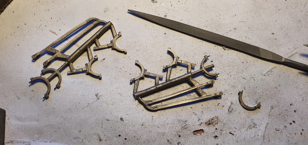
Here is the test etch being built. The original was built with a wooden chassis which is why we have designed the kit chassis as a box section.

Sandy
-
Sandy's lock down work bench.
Sandy's lock down work bench.The castings for the cylinders, slidebars and cross heads arrived a couple of days ago. Unfortunately we found that our design for the motion support bracket was way off the mark and needs to be redrawn. If fact the experience of building this test etch has thrown up a lot of anomalies and the drawing is being suitably amended as they are discovered.
It is not unexpected as we are trying to produce a kit from 4 grainy photographs, three line drawings, of dodgy provenance, and a sketch by Ian Rice.
I don't think we have done too bad for a first attempt!


Sandy
-
Sandy's lock down work bench.
Sandy's lock down work bench.I got a bit 'side tracked' (groan!) from the Neilson into building another Petrol Inspection Saloon which is now just about ready for painting when the weather improves in the next couple of days.

The issue I had with the Neilson was the fit of the motion bracket which is quite a complicated shape. With no drawings to refer to, it was a case of guess work. The shape, that we came up with on the original etch, turned out to be way off the mark so it was now a case of measuring the model and trying to get a shape that looked right and fitted.
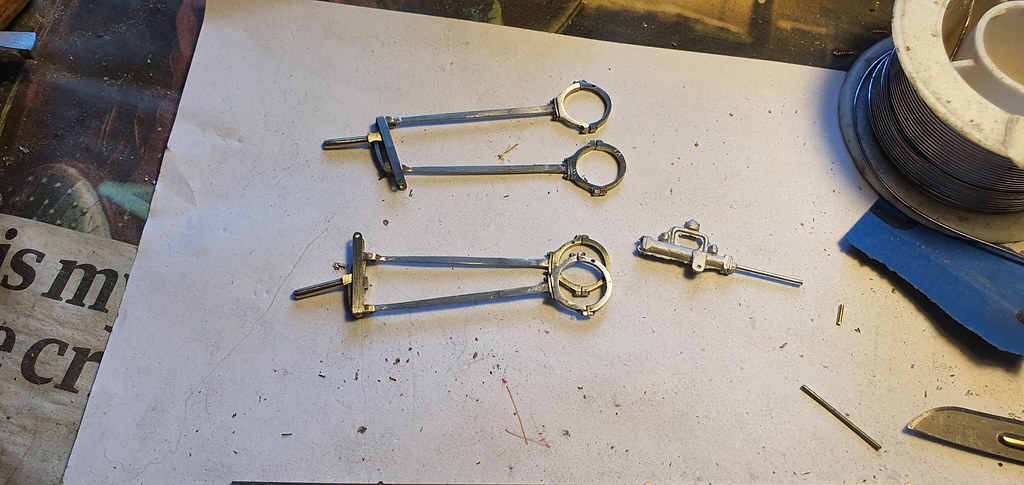
I started with a paper cut out to get a rough idea of the shape then moved on to a plastic one which was made oversize and paired down to get the fit as close as possible. It had to butt up against the boiler under the tank, avoid the tank, attach to the frames, attach to the ends of the slidebars, and avoid the throw of the rods! Easy peasy!!!
The photograph shows a couple of duds before I got a shape I was happy with.

And finally a photograph of the bracket loosely placed on one side of the loco. The overlong slidebars have also been cut down and reprofiled.

Sandy
-
The Saltport Saga
The Saltport SagaAt the 2nd hand stall at Expo-EM in 2022 I bought, on the spur of the moment, a Stanier 2-6-4T, built from a Hornby body on a Comet chassis., my main motivation being the incredible price of £20. It didn't take long to sort the running, but I hadn't touched it since, until a couple of weeks ago when I started the painting process. First, however, to find a prototype...
These loco's were mostly built with the short-lived block style lettering which I rather like, so I managed to find an example that survived the war without having that replaced (there weren't proper re-paints during the war but loco's often had touch-up jobs, which could include renewing the lettering with whatever was available). 2616 was very dirty but still had its block lettering when photographed in 1946. Sadly I have to report that I chickened out of doing the lining but it is certainly not visible in the 1946 photo!
The old lining and lettering was carefully removed with the fibreglass brush, then the model had a light coat of Halfords red primer followed by their satin black. Lettering is HMRS Pressfix, and the weathering was by airbrush and powders. The motion was toned down with AK-interactive's 'Aircraft Engine Oil'. I also added a Hornby detail pack that I was able to obtain, which included front steps, vac. pipes, screw couplings, and a few other bits. The loco. will just squeak around the curves on the layout. It's not a lot of use to me but I'm glad I finished it, even if it will spend most of its time in the display cabinet!
-
The Saltport Saga
The Saltport SagaThank you - Yes, it's huge in the context of my layout.
I also use the AK 'Shaft and bearing grease' which is a darker mix which also looks good. Both are quite transparent if you only put on one coat, so the thought of spraying a loco with it in order to tone down the colour and create an oily sheen is intriguing - Go on, you try it first !!