


Graham T
-
Posts
6,059 -
Joined
-
Last visited
-
Days Won
1
3 Followers


About Graham T

Recent Profile Visitors


Graham T's Achievements
26k
Reputation
Bookmarks
-
point mods
Chuffnell RegisAs Al said, electrofrog points for DCC require a slight modification

The latest electrofrog points have a bridge wire that is simply cut to create the ‘break’ shown above
-
Catch points
GRANBY JUNCTION - Shunting Siphons for the Up Parcels with a Manor!OK, here we go.
First, bear in mind that I use bullhead rail so the dummy blade is easier to file than flat bottom - you might need to file the foot of the main rail as well as the dummy blade in that case.
I used the sketch of a Type B safety point (catch or trap) in David Smith's GWR pointwork book, which shows that the point extends over a distance of six sleepers, so the first job is to remove those from the plain track that's already laid and glue the same number of copperclad sleepers in their place. Don't forget to gap them, either now or later.
The fourth sleeper/timber from the toe end is slightly longer than the others, on the side where the dummy blade will diverge.
Next file your dummy blade to shape - a simple taper is enough, about 20mm long.
Solder the rail that WON'T have the dummy blade attached to it to the timbers, then clamp the dummy blade to the other rail, solder the toe in place then solder the other timbers, letting the dummy blade form a nice run-off.
That's it, except for painting/ballasting to match the rest of the track.
Here are a couple more variations on the theme.
-
Brick painting
Bisley - 1990s EM Gauge9 hours ago, Graham T said:Which colours did you use for the brickwork? I always struggle with painting bricks!
There's loads of techniques and mine is no way the best but it's simple to do but takes some time from start to finish. I've primed with halfords white as it evens everything out and i can spot some of my mistakes and bring out some filler. Although as you might guess I've been struggling with getting an even finish so this building had a gentle sand afterwards which adds a bit of texture too.
I'm doing mortar first these days. This time I wanted a "new" bricks look so choose a light mortor colour (Humbrol 121). For my platforms I used up some Halfords spray camoflage paint as there's so much to do i just wanted to do it quickly - turned out a bit darker which i quite like.
Painting the bricks is just dry brushing using a cheap and flat nylon brush. I try to use it on its side to prevent the mortar being painted over - although any mistakes can be made into interesting features or weathered. The first coat is my base colour and i don't go for full coverage just an overall light covering. I do vary my base colours which i think for this one was humbrol 100. This i let dry for a few days and it all looks horrific! The next step is the final dry brush using a range of colours... these being humbrol 70,62, 100 and railmatch dark brick/frame dirt. TBH the actual colours doesn't really matter they're just shades of red/browns. I don't let anything really dry in the final dry brush so the paints all slightly mix hopefully making them not that uniform. This stage is quite nice as it seems like bricks appear!
Final step is to pick out a few bricks in which ever colour you fancy! I try not to do this that much as red bricks don't appear to me to be that uniform in colour. Then you can do some weathering if you wish. So far I've haven't done anything extra other than adding a saltly white colour here and there like on my platforms - truth be told it's where I've made a mistake, cracked some bricks or is too dark. I like to try trick my eye to not look at my errors!
Then everything is spray matt varnished with a rattle can
Hope this helps - It's quite nice painting bricks after a rotten day at work!
Will
-
Corridor connectors
Bachmann Collett Coaches – bringing them closer?There has not been a lot of progress with the layout so instead some ideas on close coupling and corridor connectors for Bachmann Collett coaches.
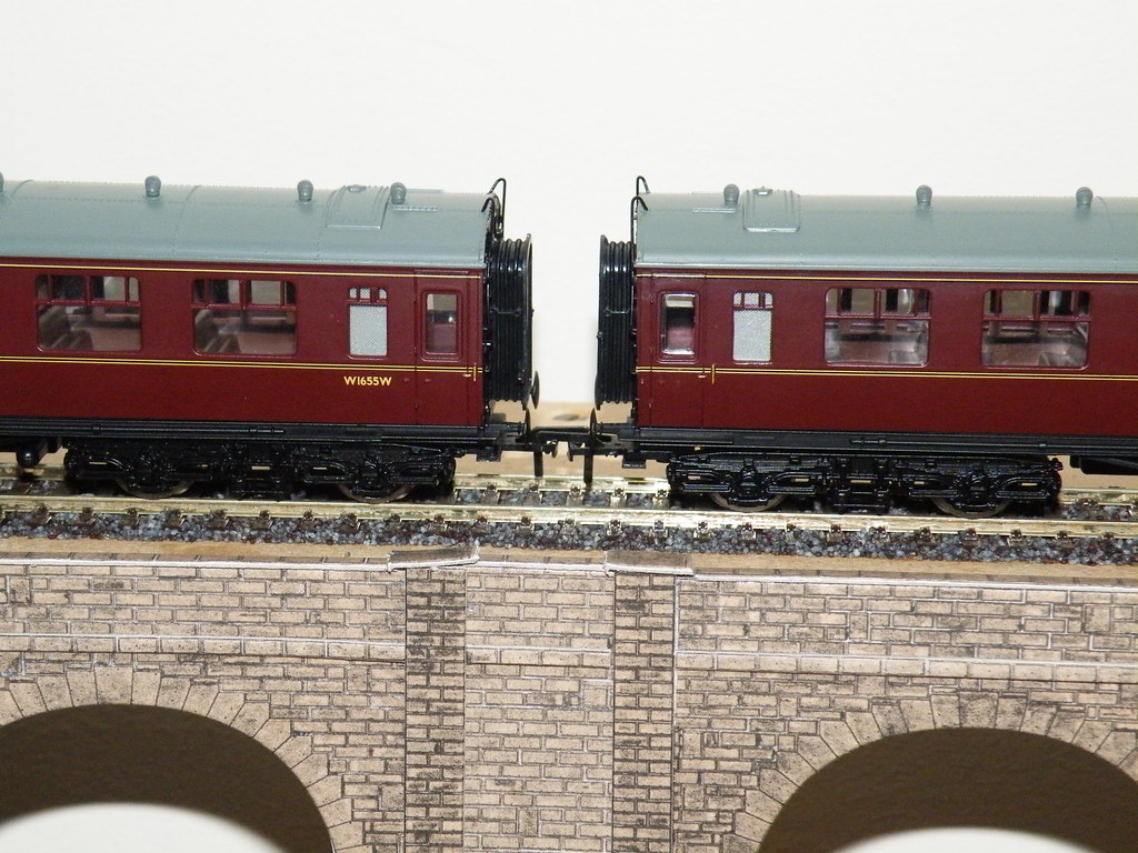
Coach Couplings as bought
As with so many Ready to Run models there can be quite a gap between coaches. Can the gap be closed up? Is it cheap to do and will it significantly reduce the value of the original coach?
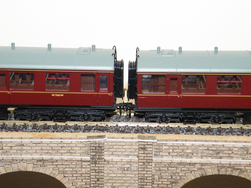
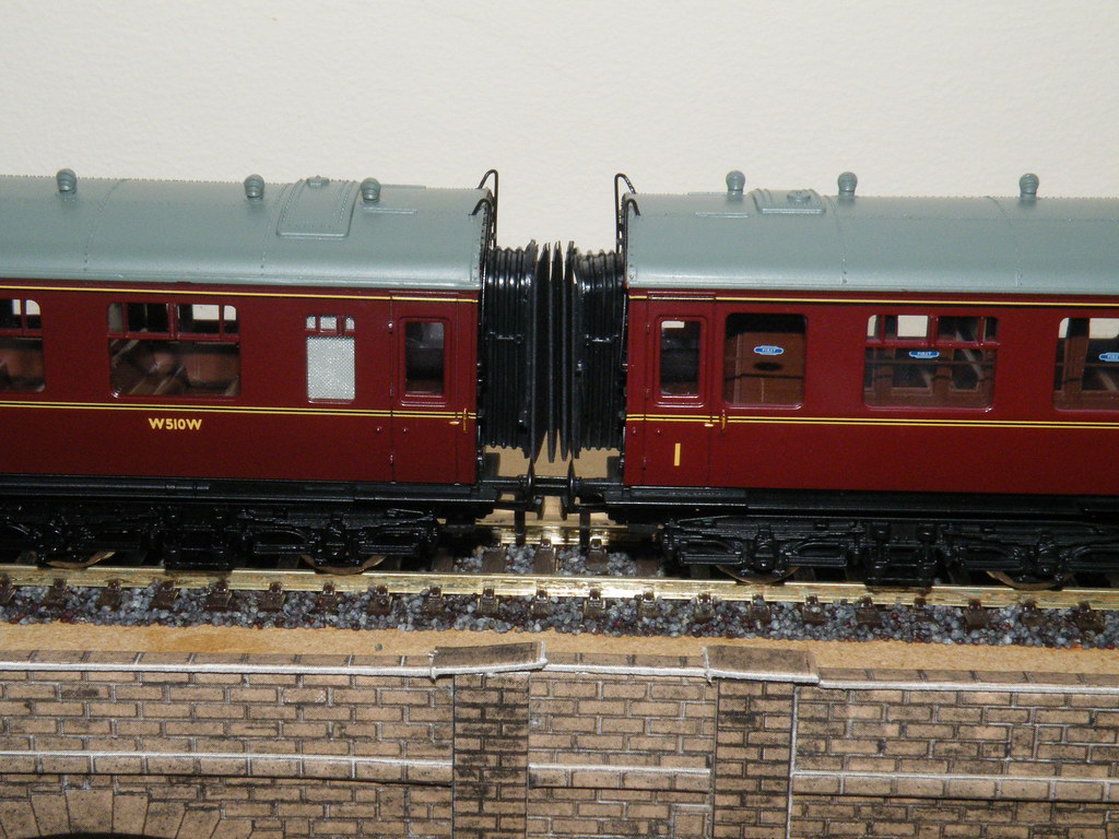
Coach Couplings as modified
I can remember the introduction of the first Collett coaches by Mainline (Bachmann). At the time these coaches seemed to me to mark a step change in the increased degree of detail on offer. I purchased my first Collett coaches back in July 1984 from the then Cheltenham Model Centre, they came with rubber corridor connectors and wire water fillers.
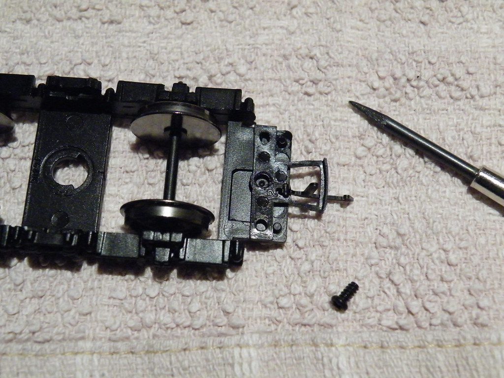
Moving the Couplings Inwards
The latest Bachmann Collett coaches are fitted with Bachmann Short Mini Couplings. The gap between the coaches can be closed up considerably by moving the couplings inwards. Remove the bogies from the underframe and unscrew and lift off the coupling. It can then be repositioned inwards taking care that is resting up against the two pegs that were used to hold it in its original position. The centre of the new hole for the retaining screw can then marked out prior to drilling. It also helps to shave off the back edge of the coupling so that it lies flat when screwed back into its new position.
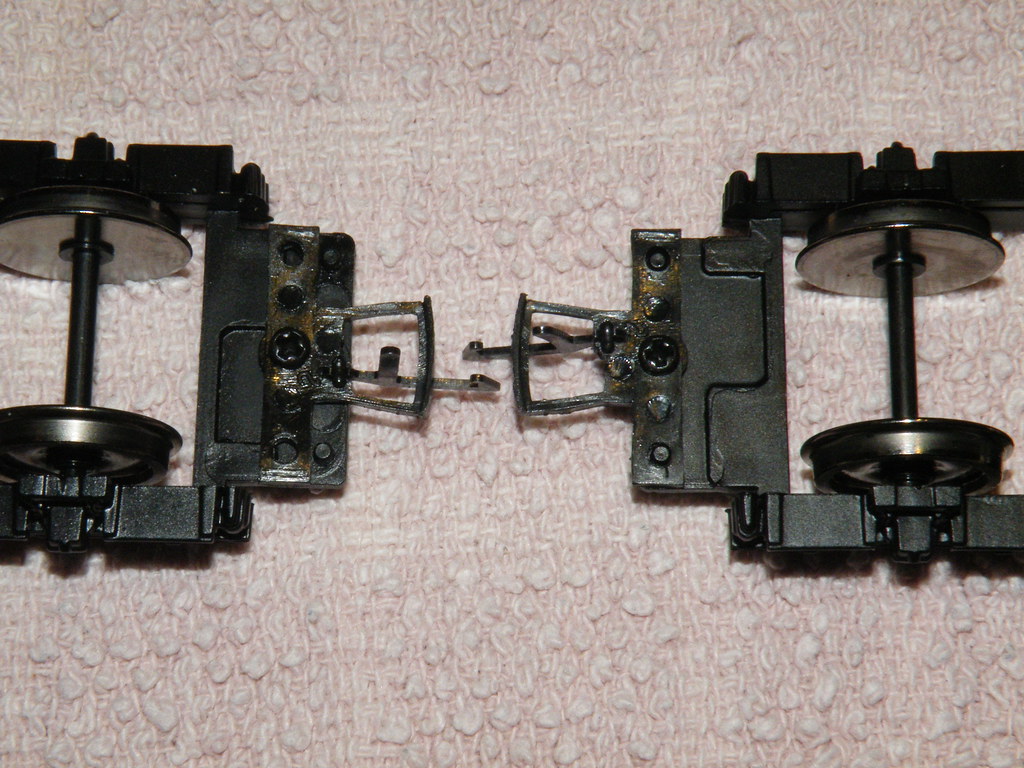
Old and New Positions
In my opinion the gap between the coaches is still very visible and I decided to see if I could improve the corridor connectors with the addition of some black ‘cartridge paper’ (Daler – Rowney A4 Canford 150g/m Jet Black card).
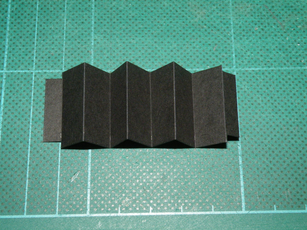
First Attempt – Single Concertina 27mm high with 12mm folds and 2.5mm indents
My first attempt was a single concertina, placed between one pair of coaches. Both ends of the connector had 2.5mm indents, top and bottom, to fit inside the existing rubber connectors which were left in place and untouched. The top corners were rounded to match the existing profile.
Two Single Concertinas – sufficient for a rake of three coaches
I thought – quick and simple and looks quite good
Two Coaches with a Single Concertina
Unfortunately whilst the rake of coaches would handle the smooth curves on the layout the arrangement with a single concertina could not accommodate the ‘S’ shaped movement at a crossover.
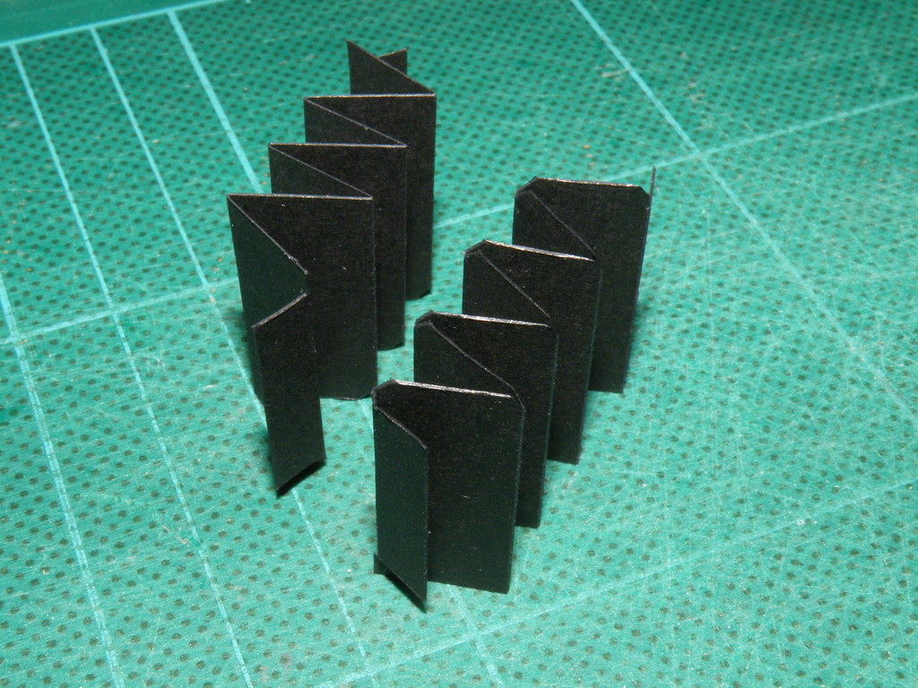
Individual Concertinas for each coach
My second and final solution was to make separate connectors for each coach that would slide against each other when negotiating an ‘S’ shaped crossover.
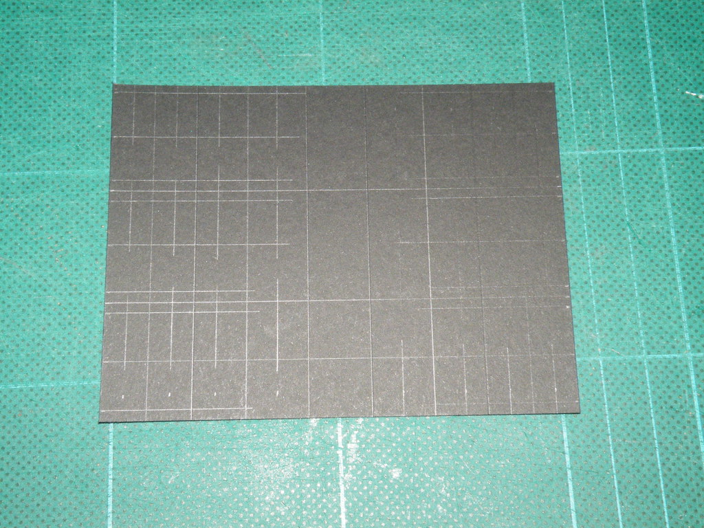
Marking Out Six at a time
To speed up the construction process I marked out six connectors at a time.
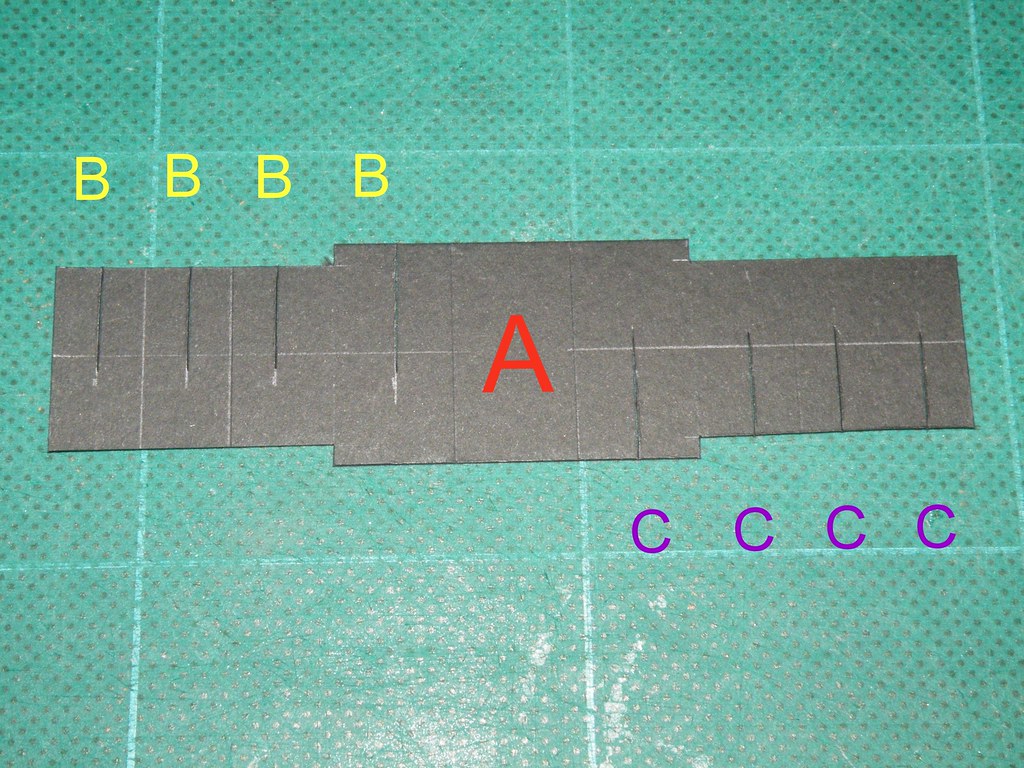
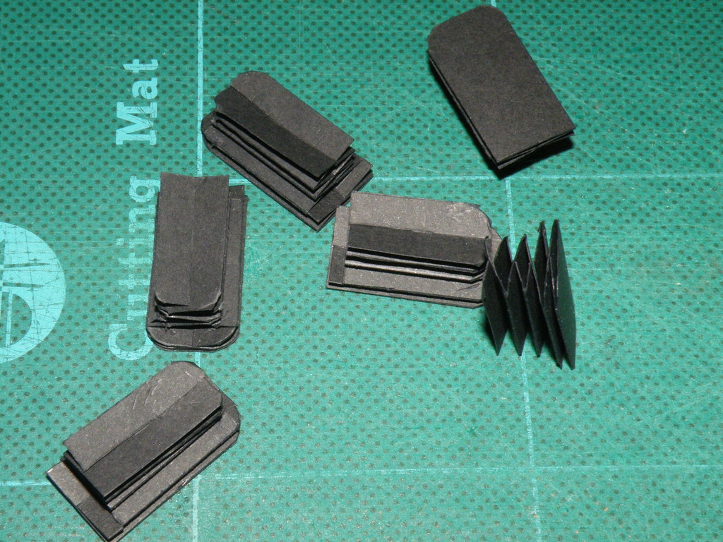
The final choice 27mm strip with 2.5mm indents, folds at 10,10,12,14,14,14,12,10 and 10mm
The centre panel ‘A’ is the rubbing plate between the coaches. There are four cut lines ‘B’ from the top and four cut lines ‘C’ from the bottom which are used to assemble and hold the connector together without the need for glue. The completed connector is a ‘push fit’ in the existing rubber connector and is held in place by the thrust from connector on the adjacent coach.
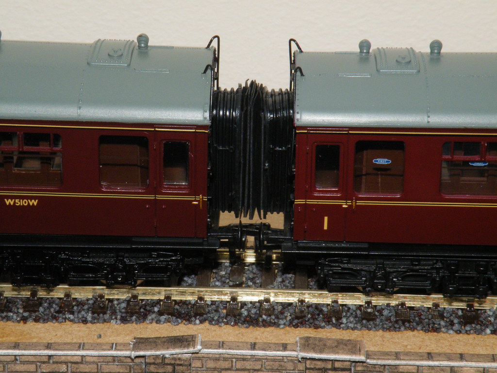
The Final Product - two individual connectors - one for each coach
Not bad - I would say. Cheap, relatively quick and easy to do and reversible should the coaches need to be sold. Must go and see if I can use the same approach on my ex-LMS panelled coaches?
Addenda
Four weeks later and I have to admit to a fault in the design posted at the beginning of November. I have discovered one set of Peco Curved points on the layout that would not accommodate the original design of connectors. The problem is that the ends of the connectors were too narrow and would slide apart and then lock. The solution is straight forward - the rubbing plates need to be at least 14mm wide. You can either glue on a separate new rubbing plate 14mm wide or the connector can be remade as detailed above using the updated sizes.
-
Coach roof weathering - powders
Chuffnell RegisOn 01/08/2022 at 18:44, NHY 581 said:The weathering of the coach appeared in July's BRM. This photo didn't make it into the final article.
To start, the roof was sprayed with Humbrol Matt Acrylic Varnish, no. 49, to provide a key for the powders.
Next, the raised ribs and ventilators were 'pre-shaded' using black weathering powder.
After this, Smoke and Dark Earth weathering powder was dusted on in various quantities using a large 'blusher' type of make up brush. Basically, this was done until it looked about right.
The powders were then sealed using a light dusting of matt varnish.
Job done.
Rob.
Following Rob's post mentioning the article in BRM I got the July issue. Not only is the article on weathering great there is another in the same issue on scenery (embankments in particular) that is also brilliant and interestingly uses the same insulation board foam as I do. The standard of these articles is very impressive.
-
Traverser - motorised
Upper Hembury, East Devon - a GWR / SR Branch lineBuilding the Traverser Drive Assembly
1) The drive
I chose to use a traverser design for storage because with my total free length of 4100mm (13.5ft) I needed all the usable space I could get and putting in a rake of sidings would be wasteful in that regard. With 910mm allocated for the storage traverser plate that left me with 3200mm free space.
A friend of long standing is a whiz at all matters mechanical, so I presented him the challenge of mechanising a traverser for me. He encouraged me to buy a stepper motor# and his solution was ingenious, many levels above my capabilities##.
What I can disclose are the mechanical aspects which cleverly overcome the problem of trying to achieve accurate control via programming “step counting”. Individual stopping points are defined simply by photo sensing devices and when one is triggered the motor stops. The operator chooses a photo interrupter to be “active” and the stepper motor advances until this one is reached. Fine control is thus achieved by the positioning to the detectors. We have achieved +/-0.3mm stopping accuracy but the acid test lies ahead at deployment.
There are cut-outs at each end if the drive is directed to travel beyond the final stop and the controls are simple.
· Five stop positions
· a direction selector - forward/back
· an emergency stop; JIC!
# My motor cost me about $A80 from a reputable on-line retailer
##He is also in the process of getting the electronics design published so I can say little about that aspect, but I suspect that anyone capable of controlling a stepper motor could design their own version as the principles are well known
-
Black 5 detailing
Detailing a Hornby Black 5I've had a Brassmasters detailing kit for a Hornby Black 5 lying around for a couple of years now so decided it was time to put it to use and to
have another diversion from the layout itself, for a while. The kit is beautifully etched from nickel-silver with many other parts cast in white
metal and lost wax brass. In addition, a Comet etched front bogie and wheels will complete the upgrade.
Maybe it's me but good colour shots of Newton Heath locos prior to 1968 seem to be a bit thin on the ground. After researching I found a
suitable prototype, no. 44890 but it meant that I had to 'split' two Hornby models to get the combination of a riveted tender with the prototype
loco's top feed position.
I wouldn't describe myself as a rivet counter but I am quite particular about models looking just right and although Hornby's Black 5 captures
the prototype's form very accurately, there are some detail aspects that I feel the need to modify, bearing in mind that my layout will only ever
be photographed, not exhibited – and what terrible secrets a macro lens can reveal!
I am not an expert on loco parts. To help, Brassmasters numbered them in the text but strangely, not on the images of the parts. I worked out
most of them straightaway but the array lamp irons of different lengths, the injectors and gravity lubricators took some time despite referring
to images on the website.
Apart from Brassmasters own instructions, I referred to MRJ 138 in which Tim Shackleton modified a Hornby Black 5 'on a budget' and the
BRM Right Track 4, Detailing and Improving RTR dvd, where Tony Wright used a Brassmasters kit on the same model. I must admit that it
was the latter that really spurred me into action… there's nothing quite like seeing someone actually do it to help overcome ones own reluctance
to dive in for the very first time.
We all want different things from our modelling and I'm sure that some will be wondering why go to all the bother if it's still 00 gauge! I guess
only when I've finished will I know if it was worth it. I hope I don't ramble on too much. If anyone sees any gaffs along the way, please feel free
to put me straight!
Tender
After separating tender top from base, I removed the tender platform with a sharp scalpel to enable thinning-out of all visible inner sides. The
bunker had been permanently coaled by its previous owner so I've left it to be 'brimmed' – eventually, after weathering – to hide the incorrect
internal shape.

The water filler was sliced off from tender platform. I want to model it open and I'm still thinking about a suitable method of modelling this.

With the edges thinned, plasticard 'ledges' fill the gaps as the tender platform is now a loose fit when it is glued back into position.


Thinned… and some! Maybe I should have started on the tender frames first until I got the hang of using the router – it took less than a couple
of minutes to 'remove the sizable chunk on the right… B***ER! If anyone has any suggestions of how to to remedy this please let me know.
Moulded lamp irons and tender steps removed and holes drilled for replacements. Another 'slip' marks the back… it takes time to get used to
working under a magnifying glass with a power tool!

Angle iron strip and lifting lugs mostly disguise butchery beneath. Brassmasters front bulkhead overlay had to be trimmed around the
permanent coal and a hole was cut through the Hornby tender bulkhead.

Battle-scarred Hornby frames. They have been thinned and the feeble springs and axle boxes removed with brutal router. Strange, you'd
imagine that the RTR details would always be over-scale rather than under!

Brassmasters' own springs and axle boxes do look better but I have to say that the moulding on Hornby's plastic spring leaves is finer than the
replacement white metal ones. Home-made fire iron tunnel entrance just about visible.

Large pic blelow; The tender frame's rear steps, which had been glued on by previous owner, had to be thinned to clear the new springs but I
would have done that anyway. At the back, etched steps, buffer steps, lamp irons (wonky one to correct!) and white metal vacuum pipes added.
The guard irons were fashioned from spare etch fret as the Brassmasters version (smaller pic) is compromised for Hornby's giant coupling.


That's it for now. Tender is awaiting Smiths or Exactoscale screw-link coupling, etched works plates a few more mods at the front end.
Not forgetting some scars to be filled but next I will make a start on the loco… and will also attempt to take some better photos!
-
Lineside fencing
Chuffnell RegisResults are in on the club fence.
holes
planted
tensioned
result
extreme close up shows it would be better to use black line rather than clear as painting then less important
-
Wagon weathering
The Sheep Chronicles : These are the adventures of a Sheep, the Works Forecat and Naughty George,Evening all,
I was asked over on Western Thunder how I went about my weathering. In response, I put together the below. Images have been featured on here but were lost back in 2020 so my apologies for the duplication for some of you.
This then is what we started with...an Ex-GWR open from Minerva. I gather there were issues with the brake gear etc but that didn't, and still doesn't concern me.
I was quite taken with the colour of the interior and rather than repaint in various greys, white etc to simulate aged wood, I decided to leave as was and add a bit of contrast.
First job was a light blast over the underframe and body with Humbrol Dark Earth No.29, applied baaway of an aerosol. I don't possess an airbrush and this was the only paint applied to this wagon.
After this, all other weathering was using Humbrol weathering powders which were sealed with Humbrol matt acrylic varnish, No.49.
This is an example of my usual tool kit for this sort of job.
Note* This is a later image. I did not use the masking tape or the dark rust colour. Later photos will include the kit I actually used at the time.
I decided to start with the interior. As I say, I decided to leave the base colour rather than repaint.
I worked, plank by plank, initially using dark earth, sand, and white weatgering powders. The contrast between planks was gradually built up.
You can see the "tool kit" in this photo.
Also used was a bit of iron oxide then smoke which was applied over all the colours, picking out the gaps in the planks.
I just carried on until it looked okay.
Hi
Iron oxide and rust was added around the various bolt heads and streaked.
Once happy, the interior of the wagon sealed using a light dusting of the matt varnish.
I then created a bit more contrast by rubbing the individual planks with a 4mm fibre brush. A bit more powdering, a bit more varnish and a bit more fibre penning until it looked okay and it was left.
Next stage. The exterior.
I decided to distress the joints in the planks and a dental spikey probe was drawn along the moulded gaps in the planks. An occasional wiggle, as well as the odd...ahem..slip...gave a less uniform appearance.
After this, black weathering powder was dabbed into these gaps. I then added iron oxide powder to the iron work in a haphazard fashion. Wheels are tackled at the same time.
After this, I started adding smoke powder to the whole wagon.
This toned down the rust and lessened the effect of the black.
I also added iron oxide to the springs and underframe, dark earth applied over the top of this toned it down. Black on the axle boxes and "grease points" of the brake gear as well as smoke here and there. Basically working by eye.
Then, once happy the powders were sealed with a light dusting of matt varnish.
Once dry, I then took a fibre brush and removed the weathering in varying degrees, plank by plank. Vary the pressure and you'll provide a bit of contrast to the colour of each plank. If more contrast is required, add a small amount of white, streaked along a plank and work it in.
The fibre brush will also provide a grain effect as you go.
Further rust was added using iron oxide, rust and a tiny bit of sand was added to the iron work and bolt heads, streaking downwards where felt necessary. I also highlighted some of the boltheads and chains with a HB pencil.
Again, once happy, a light dusting of matt varnish seals things in.
The last stage is flicking a large make up brush over the iron work. This will apply a burnished effect to the plot and highlight the texture of the powders and varnish.
And that's that....
Rob
-
OO-SF
Why Would I Choose 00-SF ?After deciding that I wanted to build my own turnouts to use with SMP/C&L plain track, I spent a considerable amount of time perusing RMWeb and other sources researching the topic. Like many others, I concluded that “00-SF” ticked the right boxes and so I am now collecting the appropriate tools, gauges, etc. to make a start this winter. Part of the preparation has been to follow the related discussions on RMWeb, hoping to pick up tips and information prior to starting.
Unfortunately, most 00-SF discussions tend to descend into a more general debate regarding its fitness (or otherwise) for purpose. This makes it rather difficult to pick out the useful content to either add to one’s knowledge or inform an opinion on it’s suitability for an individual. I suspect that some folks choose not to contribute to these threads for fear of being branded ‘pro’ or ‘anti’.
So, to help anybody in a similar position to where I was a couple of years ago I have attempted to summarise the salient points of 00-SF. Please note that while I will attempt to be as objective as possible, I have already decided to use 00-SF myself.
- 00-SF is for 4mm/1 foot, UK outline, standard gauge modellers. It has no relevance to H0 or any other scales and gauges.
- 00-SF is a label. It is not an “official” standard. Another way of describing it would be “EM-2” (i.e. EM gauge minus 2mm).
- By accident rather than design, 00-SF enables most modern 00 wheelsets to perform smoothly and reliably. While some ‘tweaking’ of back-to-backs may be required, it’s probably no more than would be required to get good running with other track standards (i.e. manufacturing issues, interpretation of parameters).
- 00-SF is only applicable to hand-built turnouts (and diamonds). There is no relevance to RTR.
- 00-SF is an option for those who have already decided to hand-build – there are more significant reasons for choosing hand-built over RTR other than 00-SF’s particular dimensions.
- Adopters of 00-SF generally apply the gauge-narrowing to 16.2mm only to switches and crossings; all other trackwork uses the standard 16.5mm.
- There are a number of people who have built and operated 00-SF and have then shared their experiences on RMWeb and elsewhere. I have only been able to discover positive feedback from these individuals. As far as I am aware, nobody has tried 00-SF and subsequently found it unsuitable for modern 00 RTR or typical kit wheels.
- To most people, the narrower flangeways delivered by 00-SF are a noticeable improvement over those resulting from the traditional standards.
- Some people claim that 00-SF is flawed and will lead to imperfect running of unmodified 00 wheelsets.
- Some people point out that 00-SF is not a standard recognised by any international or national body and so raises risks of non-interoperability for those wishing to share stock.
I would be interested to hear other people’s views on 00-SF – in particular, why they think I should or shouldn’t adopt it.
Andrew
-
Tender brakes
Derwent Spa59 minutes ago, Graham T said:Great, thank you! I need to tot up how many I need and then place an order.
If it's any help, this is how I fitted them. As you can see I didn't bother with the rear pair as the guard irons got in the way and they would be hidden by the rear steps anyway.
-
Adjustable feet for baseboard legs
Welcome to St AldhelmWork finally began in earnest building some baseboards for St Aldhelm today.
Now, I'm the first to admit my woodworking skills have always left a lot to be desired in the past, and the construction phase of this build has had me panicking slightly. I really wanted to do everything I could to make sure I ended up with a sturdy set of level and trouble-free boards. For a while, I contemplated having some built professionally, but the cost put me off, and I fancied the challenge. How To articles in various magazines have been pored over, and I've been out and bought the best tools and materials I could get my hands on in the hope I could finally put my woodworking demons to rest.
I started off with a big pile of wood: 12mm plywood for the tops (I wanted 9mm, but every timber yard in the area with a cutting service had sold out) cut to 2'x4' and 1.5'x4' size boards by the merchant; 18x69mm pine timber to form the frame; and 44x44mm pine for the legs.
The timber was cut to size then glued and screwed together in the traditional way, and by some miracle, I ended up with this...my very first purpose-built baseboard which somehow managed to sit flat on the storage unit where it will form part of the fiddle yard.
Could lightening strike twice, I wondered...turns out it wasn't a fluke, and by early afternoon I had a pair of boards. Half of the second board would sit on the storage unit, but the other part will be free-standing. Spurred on by early success, I wondered how easy it would be to fashion a pair of legs. Not too difficult at all, it turned out...
I've deliberately kept things simple. The legs slot into pockets formed by offcuts of timber, which provide a tight fit. The leg is braced by a second piece of timber, again glued and screwed in place. A second screw has been added to each side of the cross-member since the photo was taken to provide some rigidity.
Not being confident in my ability to measure and cut wood with pin-point accuracy, and to cope with any undulations in the floor, I decided to fit adjustable feet. These somewhat heavy duty ones are from Station Road Baseboards, and are simplicity itself to fit and adjust.
Buoyed on by this further success, I decided to tackle the one job I had been fearing the most - aligning and joining the boards together.
I did quite a bit of research into alignment dowels, and to be quite honest, I was daunted by the prospect of making them work. In the end, I opted for DCC Concepts' product, mainly because they provide a kit which includes the correct diameter spade drill bits and the promise of full instructions on the packet. Where could I go wrong?! For attachments, I went for sprung toggle catches (again, from Station Road Baseboards). These boards join together at a right angle, so one straight and one right-angled toggle was needed.
I really needn't have worried about the dowels. The kit was brilliant, with the instructions being pretty foolproof. Within half an hour of clamping the boards together upside down on the floor (to keep the tops in line), I had two perfectly aligned boards which locked together firmly. This time included that taken to re-attach the right-angled toggle, as it wouldn't close firmly the first time. With these, you really do have to be accurate, otherwise you'll end up with too loose a connection.
I neglected to take a photo of the two boards joined together, but I'm happy to say they fit together perfectly!
All in all, I'm really pleased with the day's work. Everything went smoothly and I was surprised just how easily it went. It proved to me just how important doing the research, buying the right tools and not scrimping on quality products is to ending up with a decent foundation. Having said that, I might end up going up into the hobby room tomorrow and finding it's all fallen to pieces again!
So, that's 2 boards down and 7 to go. I did start with two of the easiest boards today and tomorrow's construction will test my new-found abilities further. Lets hope it all goes just as smoothly...
-
L-girder baseboard
L girder baseboard constructionHi
I am contemplating using L-girder construction for part of my layout.
I have been reading Iain Rice's books. In one book he suggests 4,5,6 mm plywood for girders. uprights etc. and in another 6-10mm. I was wondering if 6mm plywood has been proven to be strong/durable enough in the long term ( 6mm is the only bitch plywood that I can get).
Regards


