


Nile
-
Posts
4,055 -
Joined
-
Last visited
9 Followers


Nile's Achievements
15.2k
Reputation
Bookmarks
-
L&B cab
Lynton & Barnstaple OO9 Loco from HeljanThere were no 'large' or 'small' cabs fitted to L&B locos. As delivered, the Manning Wardles had a 'canopy' arrangement over the front of the cab, the sides and roof being extended forward of the spectacle plate. This created a trap for smoke and steam which obscured forward vision. Page 73 of 'Portrait of the Lynton & Barnstaple' refers: "The cabs were altered, but with no great urgency and the last locomotive was modified in 1913." The modification simply cut away the overhanging roof and cab sides but made no difference to the size of the cab itself. All three locomotives would thus have run in L&B livery for at least ten years with the modified cabs, so the L&B livery application on the Heljan model is quite correct for the condition of the loco. If we're looking for detail differences, it will be interesting to see if Exe has the injector pipe raised away from the boiler. (CJL)
-
Set 1 - Under False Colours - Pt.1 - Overview
Set 1 - Under False Colours - Pt.1 - OverviewHaving rashly flung down the gauntlet and declared I'm thinking of running a third , not terribly authentic, period on Blacklade to give an airing to the bits of steam era /green diesel stock I seem to have acquired, I've actually made a start in the form of a pair of Ratio kits: two of the LNWR kits to be precise. The twist is that these will actually constitute the ER's contribution on the coaching side, until I lay my hand on some Kirk kits.
I've rather fancied the Ratio LNWR coaches since they first came out . They were new products, they looked really rather stylish with those big windows, and I suppose they were a bit cool. As I went modern image in my early mid teens, there was never any scrap of justification for buying one - until I got involved with a small informal group locally. Amongst other things we were talking about building a small branch terminus, and because of others' interests it was bound to be steam.
The LNWR seems to have embraced the concept of corridor coaches and gangwayed connections very quickly and with some enthusiasm. By 1893 they had commissioned a full train set for the 2pm Euston - Glasgow express - thereafter, for a generation "the 'Corridor'"(until the LMS formally named it "The Mid Day Scot") - and by the late 1890s they were building corridor coaches in volume for their own main line services, not just the WCJS. Ratio's range of 4 kits represent these , built from 1898-1903, and not extinct until after World War 2. I've always been surprised these kits never took off - there was a time when their MR coach kits seemed virtually ubiquitous and if you wanted a pre-grouping coach it was a Ratio MR kit or a Triang clerestory, but somehow I've hardly ever seen the LNWR kits crop up in layout articles. The prototypes feature in Historic Carriage Drawings Vol 2 - LMS , edited by David Jenkinson, as do the MR suburbans and the MR non-gangwayed express clerestories : and no doubt that's how Ratio came to choose all three types.
The twist in the story comes in 1936 , when the LMS offloaded some of them on the M&GNJR, apparently along with some ex MR gangwayed clerestories which I think are available as kits from 51L Models/Wizard , and which are far too grand, sophisticated and expensive for me to consider... A few months later (October 1936), the LMS offloaded its interest in the M&GN on the LNER. Given that the LNER promptly scrapped most of the M&GN loco fleet -, and the LNER wasn't rich enough to indulge in extravagences like "scrap and build" - I think we can take it that the M&GN was in dire need of re-equipment by that point and the LMS wasn't prepared to stump up hard cash. It's pretty clear why the choice fell on these coaches for transfer. The M&GN was a lengthy cross country main line and its big passenger traffic was holiday expresses from the Midlands. A lot of those passengers were families making 3-4 hour journeys, and by the mid 1930s subjecting them to non-gangwayed stock without access to toilets was unacceptable. The LMS duly off-loaded some of the oldest corridor stock it had in order to "modernise" the M&GN, and since the MR came to corridor coaches much later and more tentatively than the LNWR , inevitably old LNWR stock was going to feature in the transfer.
So some elderly ex LNWR and MR coaches ended up as LNER stock in E Anglia . Beyond this point we find ourselves peering into the mists of history - which are pretty thick and misty hereabouts. As a modern image modeller of Eastern leanings , my references for this are pretty scanty : 3 volumes of Historic Carriage Drawings, Harris' LNER coaches and the notes to the Ratio kits , prepared by a Mr P Millard. According to the latter "several" vehicles were transferred to the M&GN , but he doesn't say what. I have been shown a photo of an M&GN train from the mid/late 1930s with one of these coaches clearly visible , still in LMS livery . It wasn't a brake, and holiday expresses aren't obviously in need of lots of all firsts, so I think we can assume some all thirds were transferred. Whether any brake coaches were is anybody's guess: Historic Carriage Drawings does not even mention the transfer, and nor does LNER Coaches
The Ratio instructions claim extinction dates of 1950 for the brake composites, and 1952 for the brake thirds, but 1947 for the all thirds, even though more of them were built than everything else put together. Historic Carriage Drawings gives an extinction date of 1953 for the all thirds, and says extinction dates for the other types cannot be established but all types reached BR and probably became extinct 1953-5. It's evident from one or two other entries that events in apple green territory are beyond the ken of LMS coach scholars, so these will be for the vehicles which passed from the LMS to the LMR
It is quite possible the vehicles which passed to the LNER lasted a little longer. By M&GN standards, in 1936 these were relatively modern coaches. In late 1934, the LNER had set out to eliminate 4 and 6 wheel coaches - of which it still had several thousand - "except for third-rate branch lines, miners' and workmen's trains". What this meant in practice in E Anglia can be established by looking at some branch line monographs. Witham/Bishop Stortford trains were still 6 wheelers until 1940 , when they were replaced by ex GE 50' corridor coaches. The Thaxted branch retained 6 wheelers until 1946-7, when GE 50' corridor coaches were provided - working in 2 car sets. The Mid Suffolk became the last place in Britain served by non -bogie coaches (until the DoT inflicted Pacers on us) - here the 6 wheelers survived until a few months before closure in 1952, again replaced by ex GE corridor coaches working in 2car sets.
Given this , it seems unlikely the LNER would have scrapped these ex LMS vehicles before the war. In fact it seems quite plausible that after 1940, when holiday trains would have been few and far between, and the M&GN section probably had surplus coaching stock, they might have been pressed into service to replace 6 wheelers on some very minor branch. Photos show elderly pre Grouping coaches as branch sets on many ex GE and ex GN branches in the early 50s - what probably swept them away was a combination of the first round of ER closures in 1951-2 plus cascading following the arrival of the first Mk1s in 1951-2
So - a pair of ex LNWR coaches from the Ratio kits make a plausible E Anglian branch set on a very minor branch in the early 1950s. By that time they would have been in brown - on the GE, pregrouping stock was not given BR crimson, but was repainted in brown with BR lettering , and examples survived beyond 1955. When my local model shop closed down about 4 years ago I bought a brake composite and an all third , for use on the little group branch terminus project. All the other authentic options would have been difficult to source and much more difficult to build. I think they had been in the shop some time - one kit was the earlier version with plastic wheels - and they were discounted. I gave the sides an undercoat and , since it wasn't an urgent job, they sat in the cupboard , waiting for the branch terminus to happen first......
As these two kits include the only kit for a brake vehicle I have , it seemed the obvious place to start. I have very little coachbuilding experience - a couple of Ratio kits in my early teens - and Ratio kits seemed an easy place to start. (That theory took a serious knock with the very over-complicated Southern Van B kit, which took me 2 years to finish)
First stages are shown here. The exact shade of LNER brown seems to be open to question and photographic research. I bought a tin of Precision Pullman umber and another of LNER dull teak. The original idea was to mix up a suitable brown , but then I reflected that Precision paints don't cover half as well as Railmatch or Humbrol and I'd never match the colour for the second coat - or the second vehicle. So I gave the sides an undercoat in umber, in order to darken the teak top coat - and stopped there.

On restarting last week it became clear that the undercoat on the brake composite was badly affected by nibs and whiskers . I don't have an airbrush , and neither colour is available as an aerosol can. The all third was ok, if not 100% perfect . So I gave the latter a coat of teak - and the brake composite sides got a coat of Modelstrip. The teak coat wasn't 100% perfect either: Precision paint seems to love to form tiny bubbles as you brush . I did the best I could. The brake was given a fresh undercoat of umber, and then teak over. Despite my careful cleaning/degreasing of the sides and cleaning of the brush on a bit of soap to rid it of any nibs, the finish still wasn't perfect - and all sides visibly needed a further coat. There is no way you can apply three brush coats of paint and get a flawless result. I have learnt my lesson and sourced a spray can of Railmatch crimson for all the other coaches, but with the LNW set , damage limitation is all that's possible
These kits are slightly peculiar - at least to me - in that they are built round the interiors. In this they differ from the other Ratio coach kits I built long ago from the other 3 ranges. They also show early signs of the overcomplication which makes the Ratio Maunsell Van B such a laborious pig to do. I can't see that moulding the floor pan as two halves which join together with a kind of mortice joint is any improvement on the single piece floor pans found in the MR kits - unless there was an overriding technical reason in the design of the moulds, and since they produced a lot of earlier kits with single piece floores , I can't see it. Similarly, the all third corridor sides are two pieces with a tenon joint - though in the brakes these have to be two seperate mouldings , as the guard's van is in the centre not the end. However the fit of the parts so far has been excellent - the floor pan needs only routine cleaning of the edges and no packing or filing down has been required. In one or two places a few strokes of the file were necessary along the compartment partitions to get the side even. There are little locating pegs on the floor to locate the interiors (except for the toilets) - the all third has these pegs on the compartment side too, but the brake doesn't
In the process of fitting the first side, stage by stage along the side, and holding it tight to the compartment partitions till the solvent set , I managed to get solvent onto the side with some damage to the paintwork . As "cracklature" was definitely not wanted, I have rubbed down the affected panels and they will need touching in - the damage can be seen on the photo . The compartment interiors have been painted with Tamiya Flat Earth acrylic, to avoid anything embarassing being seen through the windows. I am starting to feel that if I have to apply any more coats of brown paint to this kit I'll scream
On the corridor side there are recesses for the glazing strip - why the glazing on the corridor side of the all third has to be 4 seperate recessed sections , when the brake manages with just two sections, beats me. The corridor handrail is a piece of styrene micro rod (more brown paint) applied between slots . On the all third, I made the mistake of using solvents at the retaining slots, As a result , I have marks on two windows just above the rail, where it wasn't 100% straight and capilarity drew the solvent where it wasn't wanted. Damn. On the brake third , I learned my lesson , and used the Revell Contacta bottle . In fact I've taken the heretical approach of using Contacta cement very sparingly applied as the first tack bond for the major pieces, with solvent applied to finish the join
-
Pre-grouping stock
Pre-grouping stock2009-11-29: N6 horsebox added at end of this entry.
Progress on the Buffalo and Dean goods awaits a warm weekend suitable for painting in the garage. At least that's my current excuse
 In the meantime, I thought I would show some of the other items that have served to fill in gaps in locomotive construction over the past few months. You can blame Mikkel for this
  he has recently shown a selection of pre-grouping stock on his blog illustrating various approaches to kit building/bashing, etc. I mentioned that I had a W1, inspired by his on gwr.org, and had used some brass angle to replace the Ratio plastic footboards. Most of these are experiments in getting to know the materials and the parts and etches available from different suppliers. As you will see, painting is not one of my greatest skills
  but, hopefully it will improve when I summon up the courage to complete these.
W1 from Ratio T47 parts
As I said this was inspired by Mikkel's original write-up on gwr.org. I decided to replace the stepboards with 3x1.5mm brass angle as all of my old Ratio 4-wheelers, built nearly 30 years ago, had suffered here. Various other parts including Mainly Trains etches and ABS brake cylinder and buffers were used to finish it off underneath. The buffers have had their heads cut off and are drilled for fitting Gibson sprung units. The W-irons are Bill Bedford sprung units. The livery is not a previously unknown GWR variation, but one of my painting experiments. The idea was to paint the black first, then brown and finally fill in the panels with cream. Whether it works, only time will tell...


T20 from Ratio T47 parts
After the W1, I searched through Russell in the hope of finding something I could make from the remaining parts of the Ratio 4-Wheel T47 brake thirds. The best fit seemed to be a T20, a 4-wheel brake third with central luggage and guards compartment. The basic body has been built, though using Mainly Trains brass ends. Much work remains to be done here...

Parkside Dundas W7 Beetle
More recently, I've put together a Parkside Dundas W7 Beetle. As with the W1, I've replaced much of the underframe with brass parts and added sprung buffers and white metal piping. This time, the spring units and the couplings are Masokits. I really enjoyed putting these together and am very pleased with the results. The spring units work very well and I find them easier to get working properly than the Bill Bedford type. The springs stay in place without extra packing and there is no need to try to straighten short lengths of wire.


IKB U28
Not content with all these unfinished projects, I started another one this week
 This is an IKB kit of a U28 6-wheel clerestorey luggage composite. The etch says U16, but I think that may be a four wheel arc roof variety So far, I have rolled and folded one side and added all the brass detail. The photo shows this together with an untouched side and one of the ends that has also been rolled to get the tumblehome matching on side and end. Much more work to do here.
Sometime, I'll get around to posting some of my goods stock. I've made more progress with painting thse, and some even have transfers
 But, then, painting GWR goods stock is a little easier, as long as you don't make the mistake of thinking grey is always the same colour
 51L N6 horse box
Here's one I forgot to include when taking the photos for this entry. It's an N6 horse box built from a 51L kit. This was my first attempt at a brass kit after gaining some experience with white metal wagons, etc. I built it last year as I thought I should get a bit of practice with brass kits before embarking on something like the Dean goods.
At present, it has been painted, although the roof needs toning down a bit, and is awaiting glazing, transfers and blackening the buffers and chains.

-
Kolher
Hornby - New tooling - Ruston 48DS 0-4-0We had a talk by Simon Kohlner at our railway group this evening and I asked him about the possibility of an Express Daries version. In fact he was unaware of that particular locomotive but he promised to look into it.
-
Cambrian LBSCR mod
More Pre-Grouping Wagons in 4mm - the D299 appreciation thread.I cannot go to an exhibition without coming away with a wagon kit:
Unfortunately this wagon is a bit after my favoured c. 1902 period:
On 20/11/2019 at 12:10, Compound2632 said:That brings me round to the question of further Brighton vehicles. I’ve the cattle van to finish – needs re-doing in most areas, I’ve concluded – and I’ve been eyeing up the SEF Billinton brake van kit. The two opens are both Stroudley vehicles. I’ve been thinking about the Cambrian kit C33, which is intended to represent wagons built from 1912 onwards, SR Diagram 1369. This has the same basic body dimensions as wagons built 1896-1904, SR diagrams 1370 and 1371, although these have 3” longer wheelbase. If one was prepared to ignore that, one might get away with passing the kit off as the wood-framed diagram 1370, especially if one went for the wooden sheet rail.
Undaunted:
- Wheelbase increased by 3 inches (0.04" Evergreen strip subsequently inserted; the solebar having been cut at the position of one of the doorstops)
- Axleboxes trimmed down and bodged up to represent grease rather than oil ones
- Outside brake V-hanger removed
- Sheet rail boss removed, 0.04" x 0.03" wood (Evergreen strip) bar in lieu
- Circular sheet tie bosses removed
- Chalk board at LH bottom of side
... yielding an Open A of 1898-1904 (SR diagram 1370):
The brake V-hanger has had its edges thinned by scrawking (the axleguards are molded that way) and the brake gear has been stretched - the push rods were cut off the tumbler in turn and moved out by 0.5 mm each. The sheet bar is 0.04" x 0.03" Evergreen strip, with 0.03" x 0.01" laminated on top to give the impression of a rounded profile (and also because I haven't got any 0.04" square). MekPak worked well with the Cambrian kit components and with the strip-to-strip bonds but I've had real difficulty getting a bond between the strip and the kit components - after several attempts, I used cyano to fix the sheet bar in place.
My references for this build are Southern Wagons Vol. 2 Fig. 5 and Plate 22. The line drawing shows a wagon with wooden sheet rail and Scotch brake; the plate illustrates No. 5751, with sheet rail and conventional double brakes, though with the single V-hanger attached behind the solebar. My model is a composite of the two, so I'm hoping for the best. No. 5751 was built in 1902 and has a paint date of 9/11/07; it has three cleats attached to the underside of the curb rail, to which the sheet ties would be lashed. The photos showing the circular cleats on the bodyside are all of wagons in late LBSC / SR days, so I suspect these were added after my period. As to brakes, whilst there is a photo of an 1899-built wagon with Scotch brake (Plate 24), the list of sample numbers (p. 24) includes a couple of 1898-built examples with double brakes; of course it's possible this was a later modification.
-
LSWR brake van fix
LSWR 20T Brake VanDue to a senior moment, I forgot that I'd ordered one of these some time ago from Model Railways Direct. I duly ordered one from Kernow so imagine my surprise when two finally arrived. Hey ho.
As has been documented elsewhere, the colour of these vans looks a little on the light side. As I never saw one in service prior to 1923, I'm not qualified to say whether the LSWR brown is the wrong shade. The general opinion is that it is. Having a second model meant that I was prepared to have a go at doing something about it.
The chassis unscrews with 4 screws and drops away. The false floor then comes away without difficulty. I simply pushed it out by poking a small screwdriver through the veranda opening to tap it out.
The tricky bit is the glazing. Despite my original assumptions, the door ends are not part of the glazing shell and can be removed carefully. The guards look out duckets are part of the glazing shell. Working carefully with a blade, the glue seal can be broken and the glazing can be prised inwards. I found it helpful to snap off the two retaining lugs fitted to the underside of the roof. All in all it took about half an hour to disassemble.
The lettering was removed by gentle rubbing with a scratch brush, as my usual method of IPA and cotton buds didn't seem to want to work.
I then brush painted the sides and removed duckets with Vallejo Acrylic Chocolate Brown 70.872 and was able to work around the existing handrails etc. I have no idea how accurate this is but it seems a fair representation. Refer to earlier point about qualifications. I did paint over the tare lettering on the lower plank.
The body was then given a couple of coats of Klear before transfers were applied from an old PC Models set (sheet 13). A couple more coats of Klear to seal and it was time to reassemble. I cut away the nicely moulded stove and handrail from the cabin interior as you can't see it and I wanted to add some lead for additional weight.
Taking it a step further, I fitted P4 wheels after first removing the brake gear (this pushes out after breaking the glue join) and cutting a small recess to allow it to go up against the thinned down W irons. These have to have about half a mil taken off for the axles to fit nicely in the new brass bearings.
All reassembled, just waiting couplings.

-
'Genesis' 4 & 6 wheel coaches in OO Gauge - New Announcement
'Genesis' 4 & 6 wheel coaches in OO Gauge - New AnnouncementNile,
Yes painted, once Stroudley became CME in 1870 he changed the carriage livery to be varnished mahogany, however there is only so much that varnish can do when working with older carriages, so once they got to a point that the varnish wouldn't give a satisfactory finish they got painted so that they still matched the rest of the coaching stock. The livery was officially changed in 1903 to umber and white, and then again in 1911 to plain umber.
I use Phoenix Precision P988 Mahogany for my carriages in that livery.
As we can't see the ends of the ends in the Hattons artwork I will also point out that brake ends should be painted Vermillion, again I use Phoenix for this. In this case P994 Buffer Beam Vermillion
The only carriages I have to hand to show this are Bachmann TTTE Red Coaches, modified and detailed, but still waiting for transfers!

-
Methfix method
Pressfix bad batch? UPDATE REPLY FROM HMRSOn 12/02/2019 at 14:25, chuffinghell said:I've ordered a PC set of eBay so fingers crossed they are correct......oh and still 'sticky'
The technique I have always used with Methfix, which I much prefer, and Pressfix when they have lost their 'sticky', is to treat them as waterslide. Float them into place and let them dry. Then very gently brush meths over them. Just small amounts, don't overload the brush, ( I only ever use pure sable). Too much and they can bubble up or float around and you have to re-apply water again. When dry lightly brush (or spray - which again I prefer since it won't 'pull' at the decals) your favourite sealer/varnish over them.
I would agree that many present day transfers don't have the absolute clarity and definition of those of the past. This is down to changing printing techniques and materials which may be safer to manufacture/use but don't give the same results in many cases. No easy answer really, just to make the best of what exists.
Izzy
-
TTS stay alive
Hornby TTS stay-alive solder connection points.Thought that perhaps a post indicating the stay-alive connection options with the Hornby TTS decoders might be useful.
There are two ways of adding the wires, one of which I feel is rather easier than the other due to the small sizes involved.
I have used a fine Antex Tip to help illustrate where to solder and how small the parts are. This is a new/un-used one ( which is why it looks so clean!), and has a 1mm point.
The first is how they can be added to a plain Hornby R8249 decoder on which the TTS version is based, the sound part being basically added onto it. This involves adding the wires to the diode rectifying part.
The Positive connection


And the Negative one.


As I hope you can see it's really tight to get a soldering iron tip in there. Okay if like me you use a small iron with a fine tip, a 15watt Antex with those 1mm tips, but if you have a larger iron, 25-40watt with a bigger tip... well.
So, this is the other way with the TTS decoders. The connections are on the opposite side.
The negative connection is to where the sound part is added, and is on the edge. So much easier to get to
.


And the Positive just uses the Blue wire tab. Again on an edge. I am afraid I used a spare TTS decoder I had for these shots, and the wires not needed had been removed. Both these connections are easy to remember though in that they are both the fourth one along/down.


IZZY
-
SDJR van
SDJR Road VanLast year we had a discussion about SDJR Road Vans here on RMweb, which revealed that – contrary to what one might think – these vehicles travelled well beyond the SDJR on a regular basis, including foreign destinations right up to London. For details, please see Buckjumper’s notes in the thread.
I thought I might justify one of these vans making an occasional appearance at Farthing, perhaps carrying small consignments of cheddar, cider and other Somerset delicacies to satisfy the palets of Wiltshire’s gentry.
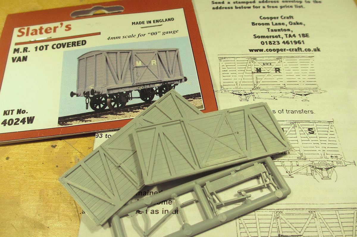
The SDJR had at least two designs of road van, one of which was based on the Midland Railway diagram D363 vans. Slater’s do a kit for the latter MR van, so I thought this would be a good basis for a kit bash. As it transpired, the project came to involve a lot more scratch building than kit building!
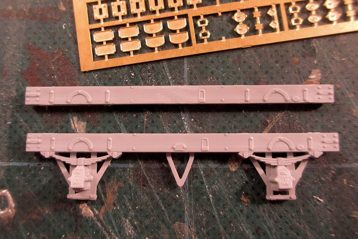
I began with the chassis. As can be seen here, the kit comes with oil axleboxes but my photos of the SDJR vans show Ellis grease axle boxes. So I removed the axleboxes and W irons, and also filed off some of the solebar fittings, to be replaced later.
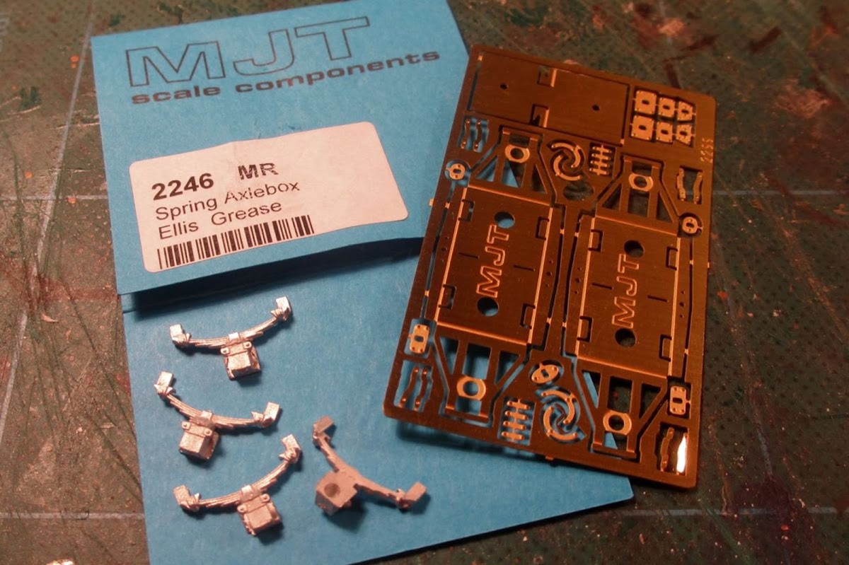
I bought in some MJT compensation units and and Ellis grease axleboxes from Dart castings.
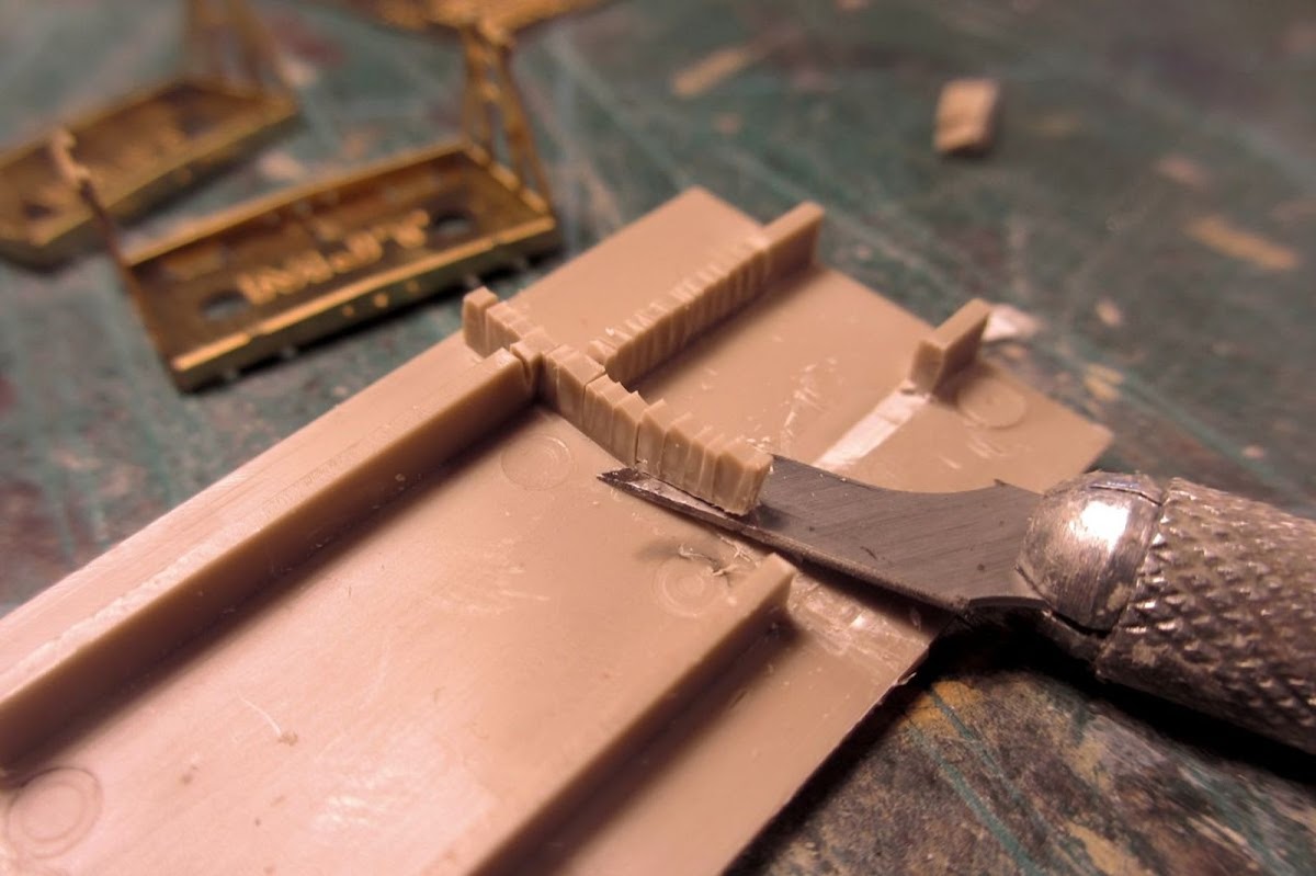
To make space for the MJT units, parts of the underframe from the kit was cut away, using what I call the “salami method”.
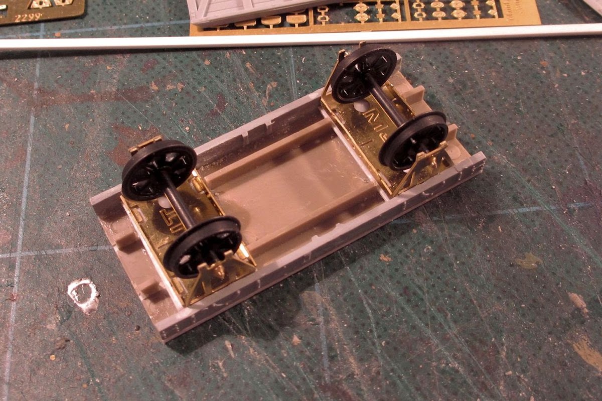
Plastikard packing under the MJT units to get the right ride height.

Then came the time-consuming part. As can be seen above, the Slaters kit has a sliding door type which is wrong for the SDJR vans. To make matters worse, the door is off-set to one side, meaning the Vs of the framing aren’t actually symmetrical. So I decided to scratch build new sides.
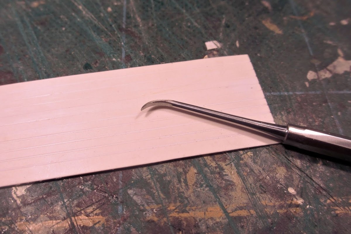
For the new sides I used plain Evergreen 0.5 styrene, and did the planking with my new scribing tool. This makes a neat V-groove, whereas other methods – eg the back of a scalpel blade – tends to make an unsightly ridge along the groove.
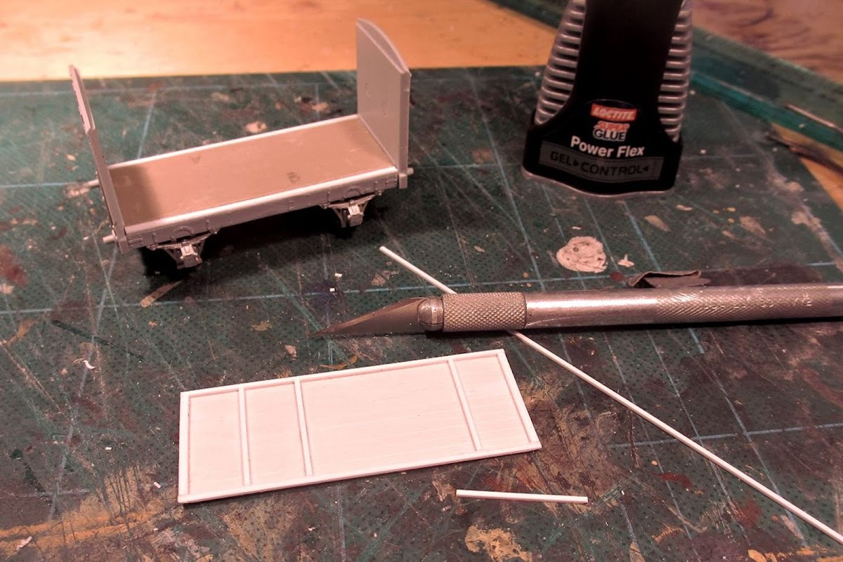
The framing was a bit tricky. The joins with the van ends are mitred, and the bottom framing is sloping in order to let rainwater run off. It helped to fit the ends to the chassis, so that I could offer up the sides to the van and check that everything fitted as I went along. I trust my fettling more than my measuring!
The framing all done.
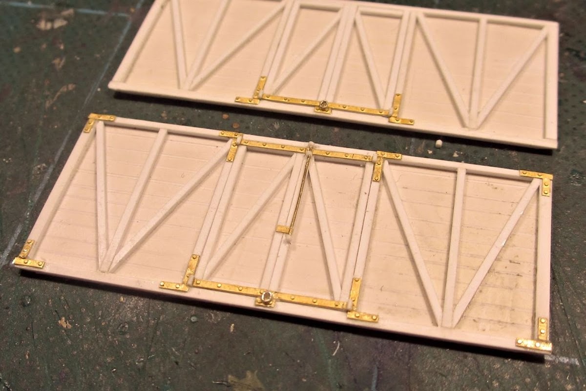
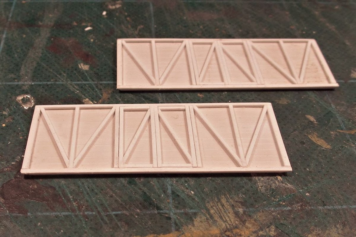
For the strapping I used a general etch from Mainly Trains. Having done a full side, I realized that the strapping should have rounded ends. I decided to leave it, but next time I’ll use plastic strip instead as this can be fashioned as required. Door hinges and locking mechanism were made from plastic rod, wire and chain.

Bolt heads were added using rivet transfers. The lower framing “dips” where each bolt is mounted. This was replicated with plastic putty filed to shape.

Sides checked against drawing. The perspective makes the side look a little too long here, but it fits in reality (honest, guv!).
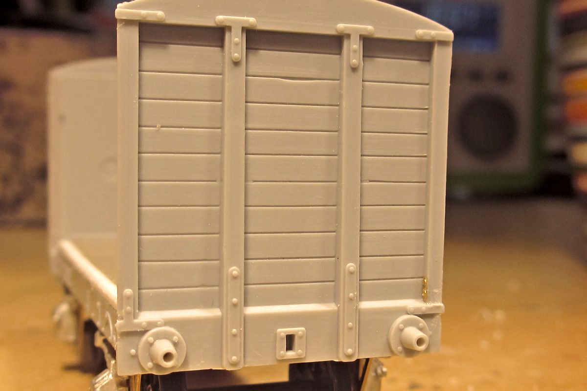
My glorious reward for scratchbuilding the sides was that the ends now looked a bit coarse by comparison! I decided to leave them as they were, except for a bit of modification to the strapping (lower left is as it comes, lower right is modified as per the prototype photo).
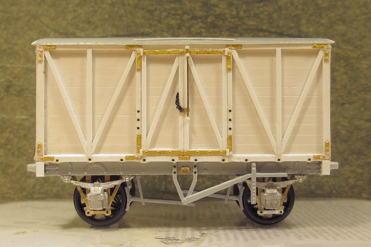
Ready for primer with brakes and various other fittings now added. The headstocks were extended a little to be flush with the lower framing, as per the photo in Southern Goods Wagons. The roof seemed a little short to me – even for the original kit – so I extended it by 0.5 mm at each end.
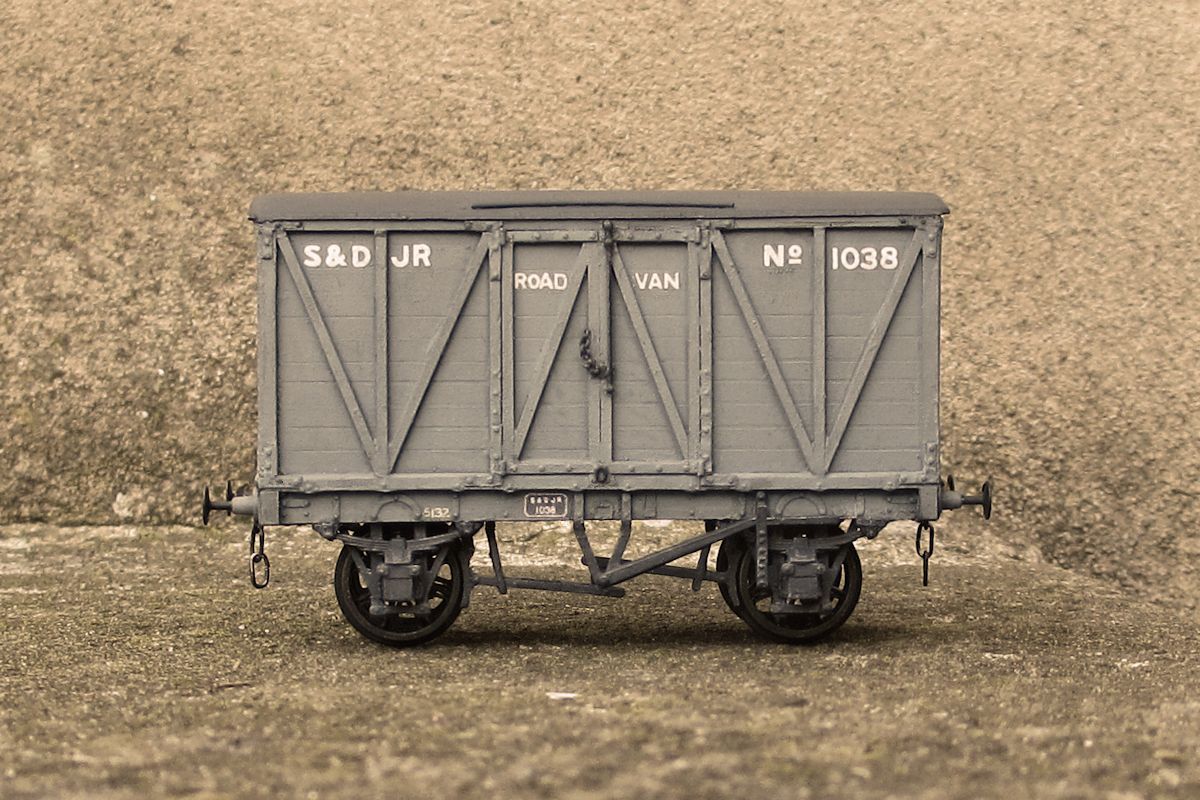
The paint job did not go well. Unfamiliar with the livery, I first sprayed on a light grey, then tried a darker one, then the light one again, etc. As a result, the grooves in the sides started filling in and revealed that I hadn’t cut them all to equal depth. Lesson learnt, the hard way! I couldn’t find any available SDJR lettering, so used individual letters from various HMRS sheets (the SR pre-grouping sheet is particularly useful). Number plates are a print from the original photo, with the perspective changed in Paintshop. The split spoke wagon wheels are temporary till I get some new plain ones.

Thankfully, the slightly heavy paintjob is not really noticeable in a layout context. One thing puzzles me though: Most SDJR wagons seem to have had distinctive black ironwork, but the 1896 photo I was working from shows no. 1038 in all-over grey, with only the number/works plates picked out in black. It’s an official photo taken at Derby works, so perhaps not to be trusted? For the time being I’ve left the strapping in plain grey but if anyone has further info I’d be interested.
Thanks to all involved for helping out with the info used in this build, very much appreciated!
-
GER exRatio
GER Ratio Coach Conversion Article?Good news. Having looked at the coach article mentioned in the OP, and compared the outline drawings on the box-art for the D&S GE coaches of the late 1890s with the Ratio sides, I see that the latter are a fairly good match for the former, so some cutting and shutting should produce a reasonable representation of a GER 6-wheel coach.
The drawings I was looking at previously represented a slightly older style.
The article concerned, and the Ratio sides against the D&S drawings for comparison, are pictured below.
Further good news is that Guy Rixon of this parish has very kindly designed 3D-Print Great Eastern Railway coach components. They are available on Shapeways: https://www.shapeways.com/product/8DZ6QHBP7/ger-6w-coach-fittings-set-a
I ordered the test print, which is pictured below. There is enough for ONE 6-wheeled coach. They are particularly good value in my view.


-
provender wagon
Pragmatic Pre-Grouping - Mikkel's WorkbenchOnwards with the modelling. I've started a Diagram Q.
These were GWR provender wagons, built in two lots. Mine is the 1903 variant with diagonal bracing, using the Coopercraft kit. From the period when transfers and good wheels (Gibson?) were included.
As usual, the build involved modifications. The Vee hanger on these wagons was significantly off-center, towards the right. The instructions don’t mention this. So both vees were cut off. The solebars need shortening, and the end brackets must therefore also come off. Here is the original solebar (top), and a modified one (below).
Then, sides and ends. The locating pips for the floor were removed. They make the floor sit too low, and the solebars in turn end up beneath the headstocks.
Body and chassis assembled. The styrene section inside is temporary, to keep those high sides from bowing inwards. The plate glass is from a bathroom scale. It’s great for wagon building, but my weight has gone up.
As provided, the brake gear does not take the off-center Vee into account, as this trial fit shows.
So the brake gear was modified to suit. Looks a bit odd, but that's what the drawing and text in Atkins et al shows (photos of these wagons are very rare and poor).
The DC1 brakes were cobbled together using parts from the Bill Bedford etch (recently withdrawn). Despite poring over prototype photos, I (and at least one other) still haven't worked out how all the parts on the etch were intended to fit together. So this is again a compromise, but not too far off photos I think.
The Coopercraft buffers have a habit of breaking, so I thought I’d try these from Lanarkshire models (no affiliation).
That’s the status for now. Paint job and plumber's hemp next.
-
Hattons AB
Andrew Barclay 14" & 16" 0-4-0ST in OO GaugeSo, I've had a few PM's and requests from "other places" how I strip down Hattons AB. I'll put this here then give people the link to as to save me the bother of replying individually.
One thing folk seem to be having difficulty with is how to separate the cab & smokebox from the Saddle tank/firebox assembly.
It follows the normal convention for RTR steam locos where the cab is a separate moulding, E.g. Bachmanns 9F. It's pretty simple on the AB considering Hatton's manufacturers have not used any adhesive. (Thanks Hatton's)
First up the cab.
After releasing the body/tank assembly from the running plate, pull the bottom of the cab moulding outwards to release the tabs at about its mid-rift area (Arrowed on the photograph), This should release the tabs from their corresponding slots in the tank/firebox moulding. The cab can then be slipped upwards and out of its location groove.
Smokebox door/smokebox is released in the same way. The tabs are on the bottom/front of the saddle tank so it's the tank that needs easing apart allowing the smokebox assembly to be pushed out towards the bottom of the tank.
Is that any help, Dave?
P
-
radial chassis mod
Alterations to the Hornby Radial chassisThe Radial chassis as produced by Hornby and Oxford has potential to fit several Scottish 4-4-0's with a bit of work. Here is how I adapted some to suit my fleet of locos - I used the Hornby one as a basis even though it took more work, as the Oxford version shows the motor fitting under the boiler and although this can be altered it meant extra effort so I stuck with what I was familiar with. The wheels of the Radial are 5'7" in diameter - undersize for the widespread 6' variety that several classes had fitted, although over the flanges it does come out at that so a pragmatic fellow could leave them as they were, if they could accept the protruding bosses that the Radial has on them, as seen here. Unfortunately there is insufficient clearance behind the splashers of HR locos for these so I had to rewheel the chassis - the boss is part of the wheel and I didn't attempt to reduce it but this is something I might play around with using some spare Radial drivers.
The dismantled Hornby chassis.
The small and large protrusions either side of the chassis have to be removed for an inside cylinder model - the smaller ones are left for an outside cylindered version.
Done - this also removes part of the motor mount so I glued the motor in place with Evostick and left it to dry for a few days, and this has held well, with no problems during extensive test running. Here is a finished one on the bench. I kept the bogie pick ups and when running will have tender pick up as well, but being firmly in the DC camp I removed all the extraneous wiring and connected direct to the motor. At the moment I am still relying on the sprung pin contact in the chassis for electrical continuity from the drivers while I was fettling it all but will probably hard wire this at a later date now I am satisfied that everything is working well.
The driving gear was swapped from the Radial to the Five axle - it is offset on the Radial and so doesn't fully fit over the knurls on the replacement axle but with some Loctite it holds well enough. Due to a lack of Hornby crankpins at the time I used BA screws, cut down, and Markits bogie wheels and as much of the rear of the chassis to suit the body being used was cut away. There is a good deal of trimming away needed from the brake blocks and ideally they should be shifted a mm or two but the existing fit is a good solid one and I doubted whether any glued one would be as robust so left them alone in situ, in a reduced form.
All in all, a very useful chassis for bodgers, and open to further adjustment as seen here. None of the chassis seen on the bench are as of yet running finished - severe case of modellers inertia - but a Loch class with outside cylinders is , and has proved a smooth runner. Here it is with its new chassis - it previously had a T9 one which was too large.
-
SECR trout conversion
Adam's EM Workbench: Farewell for nowAnd now for something completely different. In 1911, the SE&CR acquired its first ballast hoppers supplementing its traditional flat bottomed, low-sided pens which, nonetheless, lasted in some numbers into the 1960s. These were curious things with three chutes to unload the ballast (just the one bottom door on the GWR P7) designed to be operated from track level and rightly reckoned to be sub-optimal from the user's point of view especially when the wagons were - as designed - unloaded in motion. In 1915 they added another train's worth of similar hoppers of 21T capacity with the operating wheels moved upward and a platform provided for the operator. Construction was by the Leeds Forge Co., and they seem to have been at least partially responsible for the design since they some very similar vehicles to others until their closure in 1929.* This sensible and much-safer set of features was later adopted by the SR on their later bogie hoppers but, through Leeds Forge's successor, Cammell Laird (later Met Camm), more very similar 4-wheeled vehicles were built for the LMS and LNER and by BR as the Catfish and Dogfish . Characteristic Swindon conservatism saw them get Met Camm to build their P22 design when the same company had a superior vehicle available for thirty-five years...
Hornby, of course, have offered a moulded plastic version of the Trout and since examples of the second batch of SE&CR hoppers lasted into the '60s and there are pictures at Meldon which is the right end of the SR for me how could I resist? Getting hold of one has proved a bit tricky but a kind donation from @Enterprisingwestern has solved that and here we are. So apart from the lovely pressed steel side door (for copyright reasons you'll have to take my word for that unless to have a copy of An Illustrated History of Southern Wagons vol. 3 or the later Southern Wagons Pictorial) the main difference is the capacity and the consequent height of the hopper, roughly 6" lower on these early relatives. From a modelling point of view the difficult bit is the door but I have a plan for that.
Here's the donor - sadly the nicely-moulded axlebox lettering has to go and the chutes are 2mm shorter than they should be (trainset wheels, but who can really tell), as do the buffers and bendy footsteps. Vacuum brakes and their associated fittings are to be added. About an hour's drastic surgery later...
More later.
Adam
-
oxford n7
Train spotting at Finsbury SquareA recent arrival has been the new Oxford Rail N7 69670, with BR "late emblem". I've got two N7s already and despite a few shortcomings of detail, I like them a lot and they have proved to be reliable and smooth performers, so I was pleased to add a third.
However the Oxford Rail model represents a right hand drive loco, and 69670 was built with the driver's position on the left, so there were a few things to change. The body comes apart by removing the four screws underneath; there was also some glue between the cab sides and roof which I was able to break by carefully running a blade between the parts. The cab roof/spectacle plates moulding then separates from the boiler, and reveals why the cab front spectacles aren't really the right shape for a round topped firebox locomotive. Inside the cab it's still got a Belpaire firebox! The backhead itself seems to be another separate moulding and I did think of rounding it off and altering the front spectacles, but decided that would have been a chop too far, so I'll live with it.
What I did do though, was to remove the vacuum ejector exhaust pipe from the right hand side of the boiler, and prise the whistle moulding away from the cab front. I then made a new pipe from 1mm brass rod, and drilled holes for it on the left hand side in the smoke box and cab front - on these locos it ran below the handrail. I made a new slot for the whistle by drilling a hole in the new position and opening it out.
On the bunker I added the top and bottom middle lamp irons which seem to have been forgotten, and made a new lamp iron for the smokebox door. It has a very neatly moulded one, but I wanted one I could hang a lamp on!
Inside the cab, I thought about changing the reversing wheel from one side to the other and removed it, but it won't fit on the left hand side as there's no recess in the side tank for it on that side. So I left it off, and added cab doors from black Plastikard so that at least less of the inside is visible.
From then on it was really just a case of putting it all back together again. The painted 'embellishments' seem to have been characteristic of Stratford N7s outbased at Enfield Town and allocated to regular crews, and they're neatly done so I've left them alone although the white painted chimney top was a bit too much to swallow! I particularly like the printed maker's plate and the red lining on the Westinghouse pump cylinders. So I just did some light weathering on the smokebox, cab roof, running plate and tank tops, and added some gunge to the wheels and rods. Coal in the bunker, and a crew in the cab. Also shortened the couplings!
She arrived back at Finsbury Square facing the wrong way round for some reason and needed turning, and the photographer was able to follow her as she moved around the yard.
-
CIE hopper container
Kirley's WorkbenchCIE 20’ Hopper Wagons
An unusual load was the cut down 20’ container with hopper shoots added to the bottom half. Made from plasticard the biggest problem was constructing the hoppers, had five goes before getting it right.
-
goods shed
The Hollycross Railway CompanyAs you can see the small end windows just aren't big enough to get a Goods Van through, so need a little bit of work. I set to with a razor saw.....
-
B12
Potters Bar and South Mimms 1930sProgress on the Quad Arts continues and am pleased with how they are looking.
The McGowan B12 is continuing to need a lot done to it to get it to both fit together and look like a B12/1.
It was too long, the smokebox front was wrong, steps in the wrong place and the decorative valencing didn't match the castings.
After much though and a realisation you can use solvent to stick plasticard to white metal I ended up making a thin skin for parts of the frames, the smokebox, top of the running plate and cab front. This was after a very large amount of filing the castings down all over.
-
GER 2-6-0
Imaginary LocomotivesSome time ago I was watching my granddaughter driving James, very fast, round my layout. I realised that James is a very unusual locomotive, apart from his ability to speak that is. He is an inside cylinder 2-6-0. I have only found 2 such classes in the UK, One on the Caledonian & one on the Glasgow & South Western plus one in Ireland. I thought that it could be regarded as the goods equivalent of the 4-4-0. I read somewhere that James Holder of the GER considered a small wheeled Claud Hamilton for mixed traffic work, supplementing the E4 2-4-0 but never went ahead. I therefor present the LNER K10 class. An A. J. Hill development of the B12. A better loco for MT work than his heavy freight J20. It is built on a Hornby 0-6-0 chassis with a 3F footplate & original B12 cab, boiler & smokebox with front footplate attached . I have assumed that LNER rebuilt them with a round topped boiler as they did the B12/1 & the J20. 21mm Romford driving wheels are fitted. It is numbered in the unused 640xx series between the 2-8-0 & the 0-6-0. With a very old X04 motor it is a very useful engine. Roger.

-
powagons
More Pre-Grouping Wagons in 4mm - the D299 appreciation thread.On 07/06/2021 at 14:16, Compound2632 said:Bachmann have given theirs the Cc and star symbols - post-Grouping wagons not really being my thing I don't keep in my head exactly which means what or when they came in.
Just for the record, the Cc mark came in in 1926 and the star in 1933. The former cost 1s. per wagon per annum (in 1930) and was to cover all shunting and siding charges; the 1933 scheme cost 1s 9d per wagon per year and was to "cover all charges incurred in moving wagons from one point to another for the purposes of loading, repairs or other purposes beyond the usual journey regulations". The idea was to minimise clerical overheads.
All this, and more, in Chapter 1 of "The Private Owner Wagons of Somerset"...
PS: Wiltshire volume just published. [/shameless plug]
-
cirencester
Creating a believable freelance pre-Group companyThe year is 1865. The setting, The Ship at Brimscombe, Gloucestershire.
There is a proposition being put forward, you've been told, which may be of interest...and lucrative. Naturally, you went.
The gathering is small, a half-dozen people seated in the back room. Small perhaps, but influential - industrial concerns along the valleys South to Nailsworth, East past Stroud to Stonehouse, and West towards Cirencester are represented, as are canal company and carriers. Consipicuous by their absence, any of the three railway companies with interests in the region.
Your host is direct: it is no secret that the Stonehouse and Nailsworth Railway is already in financial difficulty. Construction started a year a go, and it is on schedule to open in under two years from now, yet they are said to be seeking support from the Midland Railway Company. Recall, if you will, how quickly the Midland took the Bristol and Gloucester Railway after it opened. It is also a matter of public knowledge that the Thames and Severn Canal is loosing traffic to the railways, and water to longstanding drainage and maintenance issues. The word is that the Midland is preparing an offer to buy the canal, and if the loose talk of a surveyor for that Company in this very room is to be believed, they intend to fill the canal in and run rails along it's length. In this way they hope to continue to challenge the Great Western in the area.
These are not problems for the individual companies concerned, the speaker continues, but an opportunity for the community respresented here this evening. He has a plan, it seems.
'Gentlemen, I warn you. It is ambitious, and doubtless you will be sceptical. I ask that you hear me out, weigh the benefits against the costs, and only then make your judgement...'
The Plan begins with the purchase of the Stonehouse and Nailsworth Railway by a joint committee of the Stroudwater Navigation and the Thames and Severn Canal. The railway is already well in hand and they need help. It will provide good value. The Canal Company will voluntarily close beyond Cirencester, which will form the terminal of T&SC, and the canal will form the the trackbed of a new line - there is information on the Midland's plans in the regard, it seems, saving time and money and once again allowing good value to be had from the costs incurred. There is minimal through-traffic on the Canal, it will be no great loss. Having access to the network of railways spreading across the country, however, will be invaluable.
This new line, owned by the Stroudwater Navigation and Thames and Severn Canal and Associated Interests Railway Company which will represent all those gathered here this evening, will run from exchange sidings to be built at Stonehouse. These give access to the Midland and Great Western, as seen in this map showing the planned route of the Stonehouse and Nailsworth Railway:
The other end of the line is to be South of Cirencester, with exchange sidings to the Great Western and Midland and South Western Junction Railway*:
*it got a two-decade headstart in this universe
The main route is proposed to go through Stroud, splitting from what will become the Nailsworth Branch at Dudbridge. In this we can lean on the Midland's work again - here is their plan:
Our line, however, would be continued, via Brimscombe and Sapperton Tunnel, the whole route already surveyed and deemed viable and proposed thus:
A distance of some 15 miles as the crow flies, nothing in the grand scheme of things, would enable your mills, gentlemen, to thrive. Access by water and by rail, to the ports not only of Gloucester and Bristol, but of Southampton and even London too; access to markets across half the country and, indeed, half the world. The Canals would no longer be in competetion with the railways, but working in concert with them - each able to complement the other. By owning both, we can all profit at every turn...
&c...
Well, it's not remotely likely that such an event ever took place but the background is correct and I need an excuse for my layout - a rail-served canal wharf in this area, no later than 1900.
Is it the sort of backstory parishoners could swallow?
Too much free time...
")
Schooner
-
flatiron
Deeley 0-6-4 flatiron tankThe 40 Deeley 0-6-4 tanks or Flatirons were all built in Derby in 1907 numbered 2000 to 2039, they were all originally built Saturated but by 1927 had been converted to superheated and by 1938 had all been scrapped.
The etch caters for both saturated and superheated versions, this one will be in the original guise.
As usual chassis is up first.
Dave
-
book
IRISH RAILWAYS LINE BY LINE - VOLUME 1"Railway photographer Jim Edgar has put together in this book a collection of his photos of Irish railways between 1974 and 2008. A wide range of passenger and goods trains feature, ranging from wooden bodied stock to modern air braked and air conditioned trains, and from loose coupled wagons to bogie liner freight trains. There is coverage of long closed lines including the Burma Road (Claremorrris to Collooney), Athenry to Claremorris, Mullingar to Athlone and branches to Ardee, Kingscourt, Silvermines and Loughrea. Locos include the classes A (001), B (121 141, and 181), C (first 201 class), E and the second 201 class. "
So he finally got around to finishing it, can be got via his Web Site www.markle.co.uk or the RPSI Shop https://www.steamtrainsireland.com/shop?fbclid=IwAR1x0yGGqAAQLx5vfTBWpvV9FBmgJ5MJoXYmNloLjJJh-a_uLzZ-u3ESalc
-
chassis
A P4'ed Stewart Reidpath 0-6-0THello everybody! Yes, I'm still here and workingon this (occasionally rather frustrating!) project. So, get comfortable, make a brew with some McVities (other brands are available) suggestive biscuits and read on. As its been a few weeks since I posted here I'm not sure how far I got but here goes!
The chassis was solderd together using some Alan Gibson P4 spacers which are 15mm wide. My assembly 'jigs' are 14.5mm so I needed to pack them out slightly.
The compensated axle holes were slotted out to fit hornguides from Perseverance with Branchlines axleboxes. The fixed axle was treated to my usual brass tube and wire technique so it can be removed during construction.
Coupling rods were soldered up from a set of Alan Gibson Universal ones. The kit ones were very flimsy and didn't have the joint represented in the etching.
Hornguides were soldered in place using a set of original Perseverance jigs. Notch markings can be seen on the edges of the bearings and hornguides to ensure they always match up and orientate the same way. I had to rub these down on emery later to allow side play in the centre and front axles. Without doing this the wheels would not have fitted! The fixed axle bearings were filed so that there was a minimum of sideplay to ensure the gears meshed OK.
A close up of the axlebox and hornguide markings so that they always go back in the same place and orientation.
The compensation beam was fitted but not as yet secured.
A pair of firebox sides was made from some scrap surplus etchings from an old kit. A spacer was also fitted for reinforcement as the sides are half etched and very thin.
Wheels mounted on axles and trial fitted.
As there was insufficient depth to solder in a spacer for attaching a keeper plate for the wheels I attached a keeper to the underside of the compensating beam assembly. It is screwed into a small piece of 1/16" brass soldered to the bottom of the beam. I found a piece of scrap etching from the Perseverance hornguide etch which was a perfect fit. Very apt!
Sections of small brass angle were soldered to the inside of the tops of the frame sides to support strips of thin copperclad sleeper strip for attaching pickup wires. The copperclad was Araldited in place and the 0.3mm nickel silver wire pickups soldered on to bear on the tops of the wheels. The frames are not deep enough to fit a spacer for bottom pickups. The thick wire with insulation is a torque retainer to prevent the motor from rotating under power. The leads to the motor will be shortened for the final assembly. the eagle-eyed may notice that the motor has been changed for one without a flywheel. The original didn't seem to like working when under power in the chassis. The front spacer was drilled a hole for an 8BA fixing screw to fit into an already tapped hole in the body casting. The bottom photo shows the brake hangers attached.
A trial fit into the body prior to rather a lot of fettling to rods and crankpin bearings.
I generally drill my rods to 1.5mm for AG bearings and give them a gentle reaming for a nice fit prior to final assembly. The latest pack of AG bearings and crankpins I opened seem to be 1.6mm diameter so I needed to run a suitable size drill through again and even ream a bit more to get a good fit. I have to say that the DS10 motor and Romford gearing is nowhere near as smooth and efficient as a modern can and High Level box but it does work and may improve with running.
I had to carve quite a bit of lead away in places to get better clearance and fit. This was done mainly with a small sharp chisel, smoothed off with the edge of a steel ruler to get a flat surface. Subsequent to this photo the inside of the front splashers have been relieved of a fair bit of material to ensure a good clearance for the front wheel pickup wires.
Next job is to paint the chassis and then get on with detailing the body a bit. I still need to get steps and tank fillers which I can possibly obtain from SE Finecast from their G6 kit.
Hope your tea hasn't gone cold after reading this lot!
web.JPG.65c036abfd55a0c2f7bb6fe5c56cfffa.JPG)
web.JPG.aed4a5beced6e8571483fda02b9f2dfe.JPG)
web.JPG.9dbfe077f1a8c9d7ad23087e7446a392.JPG)


.jpeg.f4d26d8a24fd065c39d406994abe65ef.jpeg)


.jpg.ec849fb48347545f3c8d7aa7815f8378.jpg)


.JPG.dcb1e1bf75fd063eba6c1895d461acbc.JPG)


")


