


mpeffers
-
Posts
91 -
Joined
-
Last visited
Content Type
Profiles
Forums
Blogs
Gallery
Events
Exhibition Layout Details
Store
Posts posted by mpeffers
-
-
Hi all,
I feel it's probably long overdue that I started a thread for my own freelance pre-grouping project - the East Gloucestershire Railway.
I've done lots of armchair (and some physical) modelling and I'll try and get these thoughts and experiences down in here in time, but to take a bit of pressure off this first post, I'm just going to sketch out the basics for now.
So here is the route map, with a few relevant neighbors (EGR in blue; MSWJR in purple; MR, GWR, LNWR and LSWR should be fairly identifiable):

The core of the route follows the proposed 1860s EGR (a scheme that planned to link Cheltenham and Oxford, but ultimately only extended the Witney Railway into a longer branchline to Fairford). Similar proposals had been made over the preceding decades, and I see my EGR as commencing a little earlier (circa 1850s).
As well as the Cheltenham to Oxford route, four short branchlines were also constructed to Northleach, Cirencester*, Faringdon and Burford.
*I waver on the Cirencester branch. Certainly, the EGR would have met the SMAR/M&SWJR there in the 1880s, but Cirencester was already on the rail map as early as 1841 and I'm not sure it was a significant enough destination for a second branchline circa 1860. I do like the idea of the M&SWJR trains initially having to reverse at Fairford to reach Cheltenham, frustrating them into still building the expensive line through Chedworth. This sort of helps preserve the Gloucestershire railway ecosystem a bit better too?
The EGR's objective was always to link Cheltenham and London. Initially, this was anticipated to be achieved through the OW&WR - who had their own London ambitions - but closening ties between the OWWR/WMR and the EGR-hostile GWR closed that avenue. Arrangements to reach London via Bletchley and the LNWR (adopted from the OWWR/WMR) were unsatisfactory and an ambitious London extension was pursued instead. This was formed of an extension of the Faringdon branch, running via Abingdon, Wallingford, Henley and Maidenhead to Datchet on the LSWR's Windsor branch. Bitterly opposed by the GWR for obvious reasons, the extension required significant political and financial support from the MR (who were keen to gain another route to South London). With significant engineering work involved - particularly crossing the Chilterns - the extension wasn't completed until circa 1890.
Thanks,
mpeffers
-
 6
6
-
-
On 11/01/2024 at 05:59, Annie said:
After doing some further reading about GWR Autocoaches (thanks Wikipedia) I decided to try out the
piggylocomotive in the middle method of operating two autocoaches in company with mynaughtynow well behaved 14xx's.According to Wikipedia suburban services around Plymouth often used four autocoaches with the locomotive in the middle, but that might be going a bit far for local passenger services in Tristyn & District.
Skimming through my Gloucestershire railways books, having a pair of autocoaches trailing (or leading) as opposed to one either side of the engine doesn't appear to be uncommon. I don't know if practices changed over time - most of the photos are from the final years of the services.
I don't think you could have more than two autocoaches on either side of the engine though, unless anyone else knows different? Possibly due to slack in the mechanical linkages.
-
1
-
 1
1
-
-
I tried making a bogie full brake out of two ends of two Triang clerestory brakes, which swiftly lead me to the question of how short could a bogie coach be?
I don’t have it to hand to measure, but I think this scaled out at around 30’. I had to shorten and re-centre the Triang bogies to prevent them from physically clashing.
At a push, I think it could pass as a conversion from a six wheel coach - I think the body length is comparable to the Ratio four wheelers and the more recent generic Hornby coaches - although I’m not sure if such a conversion would improve the ride enough to be worth it?
It’s also significantly shorter than the SECR coach you identified, so I suspect that might be a reasonable length to aim for.
-
2
-
1
-
-
- Popular Post
- Popular Post
On 22/12/2022 at 19:00, MrWolf said:The fate of the J72 I have seems to have been decided, it will become one of the two M&SWJR 0-6-0 tanks that were acquired by the Great Western upon grouping.
The numbers pretty much add up and @brumtb has kindly sent me a copy of an 80s Railway Modeller that covers the conversion. I'm bound to get carried away with it.
Very interesting - will keep my eye out for this. I've been collecting MSWJR projects for a while now but lacking the confidence to start them just yet.
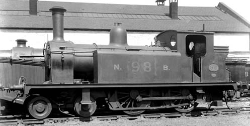
Hence the freelance/RTR bashing I'm doing at the moment. Since there was some interest in the 4-4-0T before and the picture I posted was out of date and not in very good light, I dug it out today for some better ones:
Nellie 1 provided bunker, cab, most of the water tanks and the front frame extension (from which I regret removing the steps as they now need to be replaced in almost exactly the same place). Nellie 2 provided the front of the water tanks and smokebox.
Most of the moulded details have or will be removed - in the 4-4-0T configuration, the sandbox and toolbox positioning seemed illogical, the boiler band locations didn't look right and the handrails and smokebox door handles felt very clunky. Third and fourth tank filler caps also not required, although I debated which ones to keep.
The odd cab front windows were filled in and then front and back windows opened up to take jump rings as per @Corbs suggestion a while back. I also opened out the space under the boiler and added some false frames to try and improve the look, although the chassis won't allow a clean view through to the other side without some major surgery.
Lots still to do, as ever. The chassis (a Spectrum Baldwin 4-4-0 that was still pretty expensive given it was sold as a non-runner and was missing a crank pin) needs a complete rewire to operate without its tender and there are some American details still to be removed. It also arrived covered in static grass, so needs a clean. Yet to confirm it runs, either.
I also need to find a way to attach the body to the chassis. Cab definitely needs some more interior details (although a good chunk of the space is taken up by the chassis) and I have some modifications planned for the bunker.
Filler, sanding, primer, repeat... And the usual small details (boiler bands, handrails, etc.). I think the Drummond safety valves will go. I might retain the dome - trying to decide if it's a bit small - but will probably relocate the whistle and fit a Ramsbottom safety valve on the firebox.
Feels like a lot when you type it all out 😒
-
27
-
 4
4
-
 3
3
-
19 minutes ago, CameronL said:
What's the prototype, please? To me it looks quite a bit like a Highland Railways P Class 'Yankee Tank',
I think I had the Yankee Tank (or similar) in mind when I purchased the constituent parts and started scheming. Searching for images of 4-4-0Ts to get the proportions right lead me to the NBR R Class though, with a lot of Nellie’s familiar Drummond features:
I’m keeping the outside cylinders, though 😉
-
6
-
-
- Popular Post
- Popular Post
On 09/12/2022 at 15:48, BernardTPM said:I reckon a couple of Nellies could be combined to make a nice 0-4-4T, perhaps about 50% longer than the standard body.
Or the lesser-spotted 4-4-0T:
relaxinghobby’s post prompted me to share my own effort earlier this year (including finding a reasonably convincing prototype!). I had planned to pop it in here in due course too.
-
21
-
1
-
5
-
1
-
 1
1
-
Aha, snap.
I fancy it best resembles an NBR R Class although with outside cylinders.Chassis is a Bachmann/Spectrum Baldwin 4-4-0 and I too have yet to tackle the wiring. I got the distinct feeling that American H0 RTR steam isn’t intended for disassembly…
-
7
-
1
-
-
Very nice. Also acquired a J15 at a reasonable price recently with similar plans in mind. Was thinking of just changing the cab and some of the boiler fittings, but keep looking at the tender thinking it looks a little… distinctive.
-
1
-
-
If it helps, @Annie, I first visited this sub-forum a few years ago as a bit of a novelty and it’s steadily become my most visited section. For a long time, I believed I lacked the skills and resources to actually partake, but maybe I’m getting somewhere?
As you can probably see, I’ve started too many projects to actually finish anything yet - aim for this year is to not start anything new...
813* is I guess particularly out of place in this freelance East Gloucestershire Railway scene, but probably the most critical as to whether my future pre-grouping musings might be realised. As someone who currently has zero faith in their ability to solder (neatly - there is a High Level gearbox contained within) but can passably design components on a computer, 3D printing is likely to be either a big stepping stone or a permanent fixture in future non-RTR endeavours.
*Not overtly relevant, but I’m wondering if present day 813 passes as pre-grouping? I understand the arrangement between the PTR and GWR means Swindon fittings would likely started appearing before 1923. Going for a preservation finish anyway (if I ever get that far).-
5
-
2
-
2
-
-
On 01/03/2022 at 13:39, TurboSnail said:
...the donor locos can be picked up for around £35 these days, so it's not a high budget model!
Do you mind me asking where? Really enjoyed your build in the Pre-Grouping section and it did get me thinking about a project or two I could attempt with them, but searches so far for the base model have returned only a few models at mostly well over £100 a piece. This could be down to my grasp of the prototype/German industrial rail terms, though.-
 1
1
-
-
16mm wheels, 33mm wheelbase I believe.
-
 1
1
-
-
All sounds very reasonable, Corbs. Thanks for persevering.
Think I’ll get sketching...
-
1
-
-
1 hour ago, Regularity said:
We have talked about these before. Possibly on the Castle Aching thread.
Discussed here recently, although I don’t doubt it’ll be in the Castle Aching thread somewhere also.
-
22 hours ago, 5BarVT said:
More common that long ago. May well have been upgraded with the alterations when the line was doubled (but you’re in charge of the back story and Helston kept one until 1958).
The S-R-S also has the 1943 diagram for Withington (I knew I'd seen it somewhere), with the point indicators still present. This was when the loop was extended to accommodate wartime traffic and I'm not aware of any subsequent changes, so they were likely there too until the box closed in 1956. All 14 levers are in use by this point, so this figures. I'm not certain if they were retained from installation, or removed when the line was singled in 1928 and reinstated in 1943.
I have had a go at drawing up the following, with some amendments suggested by The Stationmaster (although just noticed I have left the Outer Home in). Hopefully correctly interpreted.
22 hours ago, 5BarVT said:Single line with passenger platform and goods ‘loop’ with siding off. After doubling, you would need a separate trap protecting the passenger crossover but still only three point levers as the siding would be hand points. Two FPL, one for the goods xover and one for the passenger.
Signals would be (at doubling, assuming Down from Junction , Up to junction):
Down - fixed distant; home (1/4 mile from first xover so train can be accepted whilst another approaching on single line); inner home protecting first xover (and second too); starting on end of platform at level xing.
Up - fixed distant; junction home reading to platform and goods yard; starting on platform; goods starting at trap points; possibly Advanced starting beyond the crossover.
Shunt signal to come back through the passenger xover; shunt to come out of yard towards Dn starting.
A lever to lock the gates across the road (lever reverse allows the gates to be opened). (Make the gates hand operated so you don’t need space in the box for a wheel.)
1895
1920
Catch and trap points added, along with ground signals (hopefully in the correct places). I've also converted the line up to the box into a second siding - possibly mostly because I'll want to use it as such on the model but also in the scenario, Fossebridge will also handle Northleach's goods do some improvised additional capacity might have been welcomed. On a similar note, I feel like I want to keep the platform/dock for the visual effect. Leaning towards placing cattle pens at the Chedworth end (I assume they were positioned in accessible parts of yards for swift onward transit). Milk seems like the other plausible regional traffic that could be loaded from a platform (perhaps a wagon or two left overnight to attach to the morning Cheltenham train?).
The signal box is probably poorly located for this scenario, and would be better placed on the platform. This arrangement maybe hints at future intent (or at least provision) to extend the double track through to Northleach though. I think I'm happy with what we've proposed?
-
1
-
-
Also, this is the box:
I thought I had a picture of it to include last night, but I did not. Doesn’t add anything to the scenario (maybe a maximum frame size?), it’s just I only recently managed to cut plasticard square and I’m feeling unduly proud of myself.
-
2
-
-
Thanks all for your contributions. Hugely informative.
7 hours ago, Nick C said:Do you actually need to be able to run Chedworth-bound trains through the original platform? Not doing so saves 2FPLs and 2 signals, which is fairly significant. I think bi-directional signalling at small rural stations was quite rare.
Even as I was sketching out my diagrams, it felt tenuous. The justification in my mind is that the original platform is around twice as long as the new one and had all the amenities, although the station building/waiting room being adjacent to the crossing probably makes the difference in distance negligable. The new platform has 112' of usable length, which conveniently does just about accommodate the doors of my adopted non-bogie branch set (luggage brake - third - comp. - brake third) if the driver nails his stopping point. Strengtheners would break this, and trailing loads would risk fouling the crossing. Maybe this is sufficient though?
8 hours ago, 5BarVT said:How would you feel about a modified back story that didn’t extend the loop across the level crossing and kept it as goods only?
It sometimes crosses my mind, if only because a set of crossing gates to cover twin track at PECO's 00 gauge track spacing would need to be wide. I've not mocked them up yet but I sometimes wonder if they will look a bit silly. It would essentially kaibosh ever 'reopening' the Northleach side if I ordered another fiddle yard and opened up a hole in the right-hand end (the stopping point for trains in either direction would end up being in the fiddleyard) but, to be honest, 3 scenic feet seems like quite a poor return on a 9' long layout so I probably won't bother anyway.
7 hours ago, Nick C said:The crossing would be interlocked - there would be a gate lock controlled by a lever in the frame, possibly also a second locking the pedestrian wickets. I think the starter should be before the crossing, so that the crossing is protected when a Northleach-bound train is in the station.
Interesting to know - even in quiet backwaters? I think I read somewhere that the red disk on the crossing gates was to be interpreted as a de facto stop signal by engine crew, so assumed that the positioning of the starter could sit either side. A quick Google survey of preserved stations I can think of with adjacent gated crossings suggests that you're correct though. This is important as it would be on scene!
7 hours ago, 5BarVT said:Trap for the siding would be a requirement irrespective of gradient. Add a dummy for model purposes, no extra lever as worked with the siding point. Catch points also a requirement (I think) for 1:100, but won’t be linked to the signalling. To allow shunting, it would be beyond the Advanced Starting signal so off your layout.
Ok, that makes sense. I have some C&L chairs still somewhere so I should be able to knock something up. I think I was trying to save a lever in this exercise, but as you point out, it doesn't matter either way... If not linked to the signalling, does that mean the catch point would be sprung and on the 'uphill' line only?
8 hours ago, 5BarVT said:You will need extra levers for shunting discs for the siding and crossovers
Shunt signals have proven the limit of my understanding of signalling so far. I guess I was hoping with a loop and one siding, there were sufficiently few available movements that they might not be required? Going back to Withington, the 1902 signalling diagram has a ground signal at each end of the goods loop but they don't have a corresponding lever number. I believe they were operated by the crossover lever and just showed which way the points were set (siding or mains). Not sure how common this arrangement was, though? Obviously saves levers, although Withington had three spares so could have accommodated them.
7 hours ago, bécasse said:I would foresee two possibilities at the time of conversion to a terminus. Firstly, if the box was tight on levers, almost no alterations would have been made, so the train would arrive, be run round using the loop, and then shunted to the other platform ready for departure. Alternatively, turn back facilities would have been provided from the arrival platform which would have required a new fpl on the crossover (which was facing to a train departing from the arrival platform) and a running signal to cover the move - thus requiring two new levers.
There might have been a spare lever or two (or levers for the mothballed section of the line beyond the level crossing could be repurposed), although I guess these changes would require alterations to the interlocking even if the levers were available and maybe that would be sufficiently onerous to put the company off? It would have been operationally interesting to use the new platform a departures platform and shuffle the stock around. Sadly my fiddleyard won't accept it (currently one-third siding point, two-thirds sector plate).
Plenty to consider here. I'll get a pen and paper out when I get the chance and try and craft this knowledge into some definitive decisions. I do appreciate all the contributions here - aware that I'm trying to overlap some prototypical theory onto a mildly nonsensical scenario to justify what I've already created...
A Slight Aside
Following a train of thought I had, could a passenger train on a single line branch pass a goods train to the right (i.e. 'wrong line') if the goods train was in a loop not signalled for passenger traffic? Or did all opposing direction passes have to occur to the left? I envision a single morning and evening passenger train continuing through to Cheltenham (it'll vary the stock a bit, but maybe some of the rural folk would take to commuting), but the rest of the passenger service will be provided by a single set, shuttling between Andoversford and Fossebridge/Northleach so it's unlikely both platforms would ever be occupied at the same time. I'm just wondering what operational constraints downgrading the loop to goods only (either with it continuing over the crossing or not) would impose if a Chedworth-bound passenger train met a Northleach-bound goods.
-
Layout shots included from the phone:
-
Hi all,
In 2019, I purchased a 3'x1' laser cut baseboard thinking I could use it to quickly get a layout up and running, trying out some new techniques and gaining some experience on the way without overthinking the concept too much. Naturally (and even with the extra time at home in the past year and a bit), things haven't panned out that way and there's certainly more to do with the layout than has been done. I'm also probably starting to overthink some aspects too...

Current case in point is I am close to completing my scratchbuilt signalbox and have reached the point where I am starting to consider what should be going inside, which has lead to a desire to have all the correct equipment and all the levers coloured correctly and in order (despite the fact the box faces in towards the backscene and the interior will be mostly obscured). After a while on the fence about this, my current thinking is that it might be a good exercise to learn more about the dark art of signalling, even if the ultimate visual impact is visible.
I have seen members very graciously produce signalling diagrams on request on here. In this instance, I've tried to have a go myself and am open to feedback on the bits I've got wrong. With the exception of lever numbering, which I've left off for now. I've tried to include any required context, but let me know if I've missed anything off.
The layout depicts Fossebridge station, roughly from the siding point (just off-scene) to the level crossing (marked as a red X in the diagrams below). This is my devised chronology for the site, including the line back to the branch junction at Chedworth:
Circa 1877 - The Railway Arrives
Those familiar with the MSWJR may recognise this section - I'm working in a slightly alternative universe where the Cheltenham Extension Railway (and Andoversford - Lansdown Junc.) was largely built by the East Gloucestershire Railway (as was originally intended) and operated by that company as an independent concern (which they almost certainly didn't intend). As such, the railway has reached Chedworth a little earlier although through running between Oxford and Cheltenham won't commence until 1881. Not much to see her signalling wise.
Circa 1882 - Northleach Branch Connected
Smarting from their exclusions from the original EGR route, the folk of Northleach and Burford formed their own railway company to get their settlements on the rail map. The first priority was to connect onto the EGR, with a short branches connecting Burford to Witney and Northleach to Chedworth. In the event of the EGR proving a profitable success (possibly getting sucked in to the EGR's promotional material), the two branches could be connected to form a more appealing through route (sidelining Fairford and Lechlade).
The Northleach Branch was just over five miles in length, with an intermediate station at Fossebridge. Although the EGR at Chedworth and Northleach are at similar elevations, the land drops steeply away inbetween. To avoid the worst of the earthworks and a large viaduct, the branch followed the EGR route south for around half a mile as two parallel single tracks before divergining and desceding about 30m at 1 in 100 into the Coln valley. The EGR made what I assume to be almost minimum Board of Trade provision for the junction - a signal box and loop - and the Northleach branch itself was initially worked as 'one engine in steam' with no signalling other than one signal to protect the junction.
Circa 1890 - Northleach Branch gets Signalled
After several years of through running on a shoestring, the EGR started to consider making alterations and improvements. One of these was to provide signalling on the Northleach branch (although by no means busy, I assume a trip freight could occupy a 5.5mi branch operating on one engine in steam for a significant chunk of time and their timings were likely to be more irregular than other traffic). Fossebridge gained a signal box and goods loop, with the crossover set back inside the platform so as not to impact the crossing.
Circa 1895 - EGR Mainline is Doubled
With continued punctuality issues and grumblings from the MSWJR and GWR (with running powers over the EGR from Cirencester and Andoversford to Cheltenham, respectively), the EGR agreed to double the line between Cirencester and Cheltenham. Chedworth gains a second platform, but the twin single track arrangment is swept away and the Northleach branch junction is moved to the point at which the two routes diverge (now Chedworth Junction). To economise, the Chedworth Signal Box is moved south to the junction, with Chedworth's (rarely used) siding lifted.
To simplify the Chedworth signaller's workload, the branch is also double-tracked between the junction and Fossebridge. A short second platform is added at Fossebridge, although it is only used when trains are required to cross (I assume they will be timetabled not to do so, but the operational flexibility was considered worthwhile) as the existing platform is longer and has the waiting room. The main loop now extends over the crossing, but the former goods loop cross-over is retained (I'll concede this seems unlikely - best excuse I can offer is that it supports attaching wagons from the siding to the rear of mixed trains, which would likely have been used at times in the branch's history).
During WW1 - Fossebridge Becomes a Terminus
The contrivance continues. This change is essentially driven by the fact I only have one fiddleyard, but the best I can do is suggest that a major earthworks failure during WW1 resulted in the closure of the line beyond Fossebridge, with the wartime economy and general unimportance of the Northleach traffic not supporting reinstatement. Fossebridge was retained as a terminus, acting as a railhead for Northleach (with road transport used to bridge the remaining 3.5mi) and the nearest convenient point at which trains could be turned without also reducing the level of service at Chedworth.
Signalling Diagram
So this is my stab at signalling the 1895 configuration. The signalbox was based on the MSWJR boxes at Withington and Foss Cross, which were provided by Duttons of Worcester. As Fossebridge Signal Box would be installed at a similar time in a similar part of the country, I'm assuming the same suppliers would have been used. If practices varied between companies, the EGR's nearest 'ally' is likely to be the Midland Railway (the GWR were heavily against; LNWR likely uninterested) so I'd expect it would lean that way operationally.
Trains from Chedworth towards Northleach are straightforward - all pass through the original platform line; signals are distant > home > starter. I'm assuming no advanced starter is required as the middle crossover can facilitate shunting of the siding without passing the starter (or crossing the level crossing).
Trains from Northleach towards Chedworth can be routed two ways: 'wrong line' through the original platform then over the leftmost crossover or over the rightmost crossover and through the new, shorter platform. To signal these moves, the signals are: distant > 'junction' home (to indicate route) > starter (one for each platform) > advanced starter.
I have assumed fixed distant signals in both directions due to the level crossing (manually worked, so not interlocked with the signalling?) and as all trains will have to slow for a token exchange. The three blue lines denote FPLs. Assuming the cross-overs were worked by a single lever, I make this to be 14 levers (7 signals, 4 points, 3 FPLs). This seems good because it's the same size as Withington's frame (so the box is the right size); but also doesn't seem like an unreasonable number to have been installed when the box was new in 1890 (with a few spares) which I guess would be critical to any credibility for the middle cross-over being retained.
Outstanding Questions
- Other than levers, what else needs to go in the box? Currently I'm thinking stove, chair, table, token machine for Fossebridge - Northleach single line and 2x bells for communication with Chedworth Junction and Northleach. Anything else? Storage? Would telephones be common in fairly remote boxes by the late 1910s/early 1920s?
- I've not accounted for a trap point on the siding at the moment. Were they always required? Although the 1 in 100 will ease off significantly before the station area, it in reality would probably still decend from left to right as the branch continued towards the Coln so would this adverse gradient (say 1 in 400?) be sufficient to guard against wagons rolling out of the siding and fouling the running line?
- Similarly, I've not accounted for any catch points protecting the station/level crossing from anything running away down the 1 in 100 gradient. Is this reasonable? The railways were a relatively mature system by the final track alterations in the mid-1890s, by which point uncontrolled runaways should have been relatively rare...?
I've rambled a lot. I hope it made some sort of sense and thanks to anyone who read through the whole lot, as well as for any pointers/comments/questions its raises.
Cheers,
Matthew
-
17 minutes ago, Compound2632 said:
Yes, but the long-distance journeys were, I would suspect, largely made by passengers travelling on or off the system in the Great Northern or Midland through carriages.
Therein could lie the answer? The MSWJR seemed to mainly deal in through services - even sold on most of their tank engines.
I fear we’re digressing a little bit, much as I am enjoying the discussion. Might either start my own topic (gulp) or move this over to the freelance PG thread.
-
1
-
-
1 hour ago, TurboSnail said:
It might not just be passenger traffic these could be used for... Does your line have an industry that runs workman's trains? Or engineers trains might consist of a couple of ballast wagons and an old coach converted to a workshop/shelter. I'm sure there are other excuses to run them too!
I think the Cotswolds mostly just dealt in milk and livestock. The MSWJR did open their own quarry at Foss Cross (I’m fairly sure they used it for their ballast, not sure if any was sold on also) and there were exchange sidings for a short-lived quarry at Charlton Kings, both of which would have been on EGR metals had they opened the Cheltenham-Oxford route in advance of the BCDR and MSWJR.
34 minutes ago, Edwardian said:One thought is how typical the M&SWJR was for a line of its size in that regard?
Possibly not very? It’s difficult to say. They even fairly extensively rebuilt their non-bogie stock (new roof profile, electric lights) not long before disposing of it. My best guess is that the company simply had enough bogie stock to cover for the timetable (possibly as the number of through services were reduced?) and the non-bogie stock became surplus to requirements. I’m not aware that any of it was sold on, though?
-
1
-
1
-
-
Lovely.
Between that and the price you’ve found, I’m very tempted. Working theory for my EGR was that non-bogie stock had largely been withdrawn by my post-WWI period (this was the case on the M&SWJR, which is steering a lot of my decisions) but perhaps I could retain a full set or two for some of the unglamorous local traffic...
-
1
-
-
On 08/07/2021 at 22:28, k22009 said:
At present assuming the bodywork goes together fine i would make it available to others as i did with the Fowler Dock tank, probably once again with chimney, dome, smokebox door and whatever else i can sort out in resin.
Expect I’d put my name on the list for that (although it remains to be seen if I can actually assemble a kit...)
There’s a simple elegance to a lot of the MSWJR’s fleet - I’m a big fan. I believe the 4-4-4Ts were one of the companies poorer acquisitions, lacking adhesion, barred from freight turns and only run facing forwards (I think the short coupled wheelbase-long overall length combination made them quite unstable, particularly in reverse although I’d have to check my Mike Barnsley Vol.II again). The MSWJR spent most of its existence short on motive power and money and had relatively few sheds for its route length, so versatility was very much the name of the game.
There are some photos (prototype and models) available on this site, if you’ve not seen them:
http://swindonsotherrailway.co.uk
It’s an excellent resource, but you do have to dig around a bit to find what you’re looking for.-
2
-
-
Thanks - good to hear.
-
1
-
-
How did the 813 kit go together? I’m trying to put aside my reticence to work with metal and soldering and give kitbuilding a go, but kits seem really quite expensive (from the perspective of not knowing whether you can successfully assemble one - I appreciate RTR is increasingly expensive too these days) and few of the oft-recommended starter kits are of prototypes that motivate me. I have many fond memories of 813 on the SVR, though...
-
1
-


East Gloucestershire Railway - Local Goods and Working Patterns
in Pre-Grouping - Modelling & Prototype
Posted
As mentioned, I've been doing more research and computer-based work on this project recently. In particular, developing a working timetable and locomotive rosters (to help develop rolling stock requirements).
This has raised a couple of big gaps in my knowledge and I was wondering if members on here have any information to share or recommendations for books or other reading.
The first is around local/'pick-up' goods services. I find these are often referred to, but I haven't been able to find out much about how these trains were composed and worked. It seems as though they generally were worked in one direction only (and then returned non-stop to point of origin later...?) but this seems as though it would generate a big disparity in mileage and time taken to deliver goods, depending whether or not it was moving with or against the direction worked. I'm also interested to know whether the composition of the trains themselves were re-organised at all en route. They were presumably a mix of loaded and empty wagons, both to be delivered or collected. Would time be set aside, at major stations say, to make the next few stops on the line more efficient to shunt or was that not really required?
The other constraint is working patterns. I gather by the BR era, train crews would hand locomotives over at certain points and long turns (I think I've seen one that was over 20 hours) and balancing turns on locomotive rosters over a couple of days were not uncommon. However, I believe the LBSCR assigned individual locomotives to particular drivers and firemen, to the extent that their names were painted in the cabs. For locomotive rostering circa 1900, would it be more common that the turn would start and end at the same place, reasonably within a maximum shift length (say 12 hours?) so that the turn would be worked by a single crew, who would end up back home at the end of it?
Thanks for any help in advance,
mpeffers