


dale159
-
Posts
472 -
Joined
Content Type
Profiles
Forums
Blogs
Gallery
Events
Exhibition Layout Details
Store
Posts posted by dale159
-
-
With reference to ongoing problems at London Waterloo due to a signalling location cabinet going up in smoke

A nice up to date picture from Good old Auntie Beeb.
Dale
-
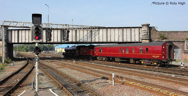
These are more recent colour lights, the original colour lights were mounted on the bridge
http://www.nwrail.org.uk/rh130928-45699-chester-x.jpg
Earlier colour lights
Excellent, many thanks.
Dale
-
Hi Dale
It might be worth checking that the IR extension (splitter) will work on the base station without the Pro Box.
I say this as the ability to use the splitter and use up to 4 additional IR receivers, is listed as one of the additional features that the Pro Box provides over the basic system.
Regarding the sync'ing of rosters between handsets, this is a very useful feature and only becomes a problem if you wish to store more than 40 locos in the systems memory.
Presumably you are using more than 40 locos with this system?
If not, I cannot see any reason to remove the Pro Box.
Ron
.
Thank you Ron.
I probably ought to try that but I am fairly confident it will still work!
Dale
-
Quick hour in the garage this afternoon/evening doing signalling preparation work.

3rd rails have reached the carriage sidings (swaps sides briefly where the ground signal will be) need to buy another pack of insulator pots as I have run out.

Then I marked out roughly where I thought the over bridge ought to go using a piece of 4x1 timber up on its end and cut away the cork so that it sits flat on the MDF top underneath.
Dale
-
 2
2
-
-
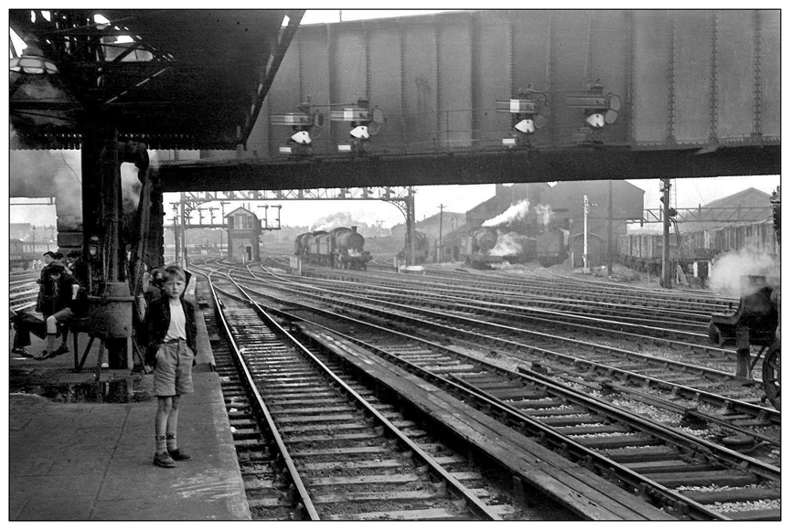
Chester had LNWR lower quadrants mounted on a bridge, replaced by colour lights on the same bridge and now the heads are LEDs - still on the same bridge
LNWR
https://www.chesterwalls.info/chesterpics5/Chester%20Station%20C1956.jpg
That's excellent thank you.
Would you be able to point me in the direction of a photo with the colour light signals on that gantry?
Dale
-
You have answered it Tim. During the 1980s there was a decision to provide junction indicators on reversibly signalled lines where the only option for a train travelling in the wrong direction was to rejoin the correct line via a crossover. This was decided on in order to cater for the situations where some Drivers had become confused approaching such signals and thought they were going 'straight route' and hence took the turnout too fast. I don't think these 'over speeds' ever led to a derailment but there were a number of hair raising examples hence the provision of a JI.
Somewhere I've got what was probably one of the first, if not the first, facilities drawings produced showing this principle and it was drawn to formalise my initial sketches for Worcester resignalling back in 1984. Whether it is still a standard procedure I don't know - but Simon will (although I think it is) but it was applied during the West of England resignalling schemes at Westbury and Exeter irrespective of turnout speeds plus alterations on the then WR reversibly signalled routes..
Thank you Mike.
I believe the whole of the Exeter Central area is a blanket 30mph area rising to 70mph on the Up Waterloo line by the Pennsylvania Road overbridge with a 15mph limit in and out of the bay.
Dale
-
Carstairs Junction has a pair Down Loop and Down Main (Northbound) mounted off the footbridge. A search for Carstairs Station brings up a few photos where they appear in the background of shots.
Paul.
Thank you Paul.
A quick google has come up with this photo looking up at the mountings of the gantry on the underside of the bridge, very useful image.
Dale
-
Dale, just curious but how long did your handsets used to last on a set of batteries?
Also how directional is the infa-red connection? i.e. How easy is it to point it in the 'wrong' direction and loose connection?
Hi Nick,
The batteries don't seem to last all that long I couldn't tell you exactly how long as mine has only really seen use in short bursts for testing. As for infra-red signal I have a Pro box with splitter for an additional 4 infra-red receivers on cables although I didn't use this for this test.
Also I found when using the pro box if I changed handsets the base station remembered all the locos off the previous one and transmitted these to the second one overrighting those that were already on there so I intend go without the pro box and just use the original base station with the splitter for additional receivers.
Dale
-
Afternoon
Sorry to dig up my old thread but I thought I'd share something which I have just discovered which will make my life operating my layout a bit easier.

So, with reference to the above picture, on the left we have 37410 (address 7410) programmed into the left hand handset and on the right we have 37025 (address 7025) programmed into the right hand handset. Neither loco is listed in the stack of the opposite handset.
I wondered if I added the locos to a consist of the same number (I chose consist no. 2) in their respective handsets whether I would be able to drive both simultaneously, and the answer is yes you can!
Shame that my pair of 37s didn't run at the same speed for the test but I don't think that is because of the controller set up, might have to try it with another pair of locos just to be sure.
Dale
-
Sorry, I meant as in train movements and what trains will go where, as this will effect what signalling you need.
Simon
Ok, it's fairly straightforward, track plan and my thoughts towards the bottom of the previous page - http://www.rmweb.co.uk/community/index.php?/topic/73981-brixington-town-signalling-problems/?p=2891192
Dale
-
Hi,
I just was idling flicking through this thread and just caught the above comment, if you wish, I can have a look through and provide comment on the signalling, but I would need to know the operational requirements (which you may have already covered and I haven't read)
Simon
Hi Simon
When you say operational requirements, I'm not looking to have train detection or interlocking or anything like I have seen you have on your layout, just to keep it simple with a series of switches on the control panel, I was mostly looking for advise on signal location and which ones should have feathers or route indicators including shunt signals and such like.
Dale
-

Something like that from track level
(Would a steel Girder bridge have a white patch for semaphore signal siting painted on it?)
Dale
-
Evening,
I've been toying with a couple of ideas in the signalling department.

Platform 1 is quite straightforward, I filled the platform with 5 mk3s which left me with about 6 inches spare so a decent amount of space to place a signal without it being crammed in right at the end. Of course I could have a gantry with an arm either side with to give platform 2 a signal in the reverse direction perhaps with a feather similar to E315 and E415 at Exeter Central.

The tricky one is platform 3, I have positioned the HST with the TGS door right up to the end of the platform, this way the rear power car of a 2+8 is clear of the scissor crossing on the lift out board. The problem then is the starting signal ought to be ahead of the front of the train so mounting it on the platform isn't possible and as can be seen in the picture there isn't much room on the ground to have a signal on a post, so instead I thought I would have a road bridge across the layout at this location (also convenient for hiding the electric lines going off scene) upon which I could place a signal on a small gantry. Although I will be using colour light signals I may even paint a white patch on the bridge behind as a siting aid for a previous semaphore signal as there are still many of these visible on the railway today even if the associated signal has been replaced with a colour light. I have been looking for prototype pictures of similar arrangements but so far I've not found any, any links to such photos would be much appreciated.
Dale
-
Here's an example of a signalling oddity.

At Exeter Central on the left platform 2's E315 with feather and on the right the rarely used platform 1's E415 without feather yet just beyond the bridge these two tracks have exactly the same routing option
Dale
-
You might also want to place an additional position light on the line running from Platform 3 for shunt moves to reverse behind - there are lots of these at locations throughout Devon, Drew up suggestions whilst waiting for a train:
I like the idea of the ground signal for a shunt on the down main from platform 3 into the 3rd rail platforms, I think I will do that but I might move it back behind the facing crossover.
RE which region controls the signalling the nearest example that springs to mind is what used to be platforms 4a and 4b now 4,5&6 at Reading although in practice those platforms are a separate entity from the rest of Reading station
Dale
-
I like those units, used to travel a lot on them in the Thames valley.
Will you be eyeing up the Bachmann class 117 when it comes out ?
Hi Rob
Not immediately, maybe a few years down the road, I'm quite happy with my Limby ones, which reminds me I must finish of the transfers on my blue grey one which is currently in my room gathering dust. I'm not a fan of doing transfers, several projects I've started seem to have ground to a halt at the transfers stage!
Dale
-
So there are 2 double track mainlines leaving to the left with the sidings in the middle?
First thought: if you are trying to emulate Western Regiom practice then they tended to add extra arms to their junction indicators for the straight ahead routes on loop platforms. A prime example would be Platform 1 at Newton Abbot; the east end has a no.1 indicator for the only main aspect route (to the up main) and the west end has no.1 and no.4 indicators for the 2 available routes. So if you're feeling really keen you may want to add an extra feather to signals 1,3 and 4 (or you might not).
Second thought: The route indicators might be simpler in reality maybe an E and an S rather than ES and CS?
Any use?
Thanks Tim.
Sorry for the slow reply, I understand what you are saying.
The thing with this layout is that it's half western region and half southern region so signalling principles might be looked upon differently between the two, that said the would signalling system would be controlled by a single signal box or panel so would more likely be Western region given that they are the operators of the through lines.
I agree with you thoughts for simplifying the shunt signal route indicators down to 'C' and 'E' of maybe I might change it to 'H' for Headshunt.
Dale
-
Quick knock up on MS paint of my thoughts for signalling.

When I started the layout I was hoping to have a home signal with multiple feathers on the outer loop line controlling access to the station alas as it turns out I'm not quite going to have the space for it so it will be off scene.
Signal off platforms 1&3 bog standard 3 aspects.
I am in 2 minds whether or not to provide a signal for a route from this end of platform 2.
From Platforms 4&5 again 3 aspects both with No.4 feather for moves towards the main line, and shunt signal with separate route indicator for the Engine Spur (ES) and the two Carriage Sidings (CS) maybe would these need one each?
And finally shunt signals to exit the Engine Spur, Carriage Sidings and Parcel platform with its protecting catch point.
Thoughts and other suggestions much appreciated
Dale
-
Afternoon.
I'm still alive and work is still progress very slowly.
Just one picture

Ballasting is as good as complete bar a few test runs and freeing up a few points.
I had to replace a small section of track on the inner through loop up by the top crossover when I saw that the rail had popped out of about 6 inches worth chairs probably as a result of my efforts to remove surplus ballast with a screwdriver.
I have finally got my carpenter friend who had agreed in principle to cut a grove in the wood for the second control panel as per the first one so when I get that back I'll be able to put it together and make a start on that. I'll also be changing the back of the original panel from a 3 inch to 4 inch length of timber to protect the breakout boards.
One thing I must consider alongside the track plan on this panel is signalling for the layout which also means its nearly time to think about the actual signalling on the ground as well, I have a few ideas but I think I need to put them onto paper and then perhaps present them on here or I might even start a separate thread in the signalling forum for some expert help.
Then other things to consider would be smaller lineside details like location cabinets, cable troughs and even 3rd rail feeder cables from fine wire.
Dale
-
1
-
-
There are one or two spots of light bleed which I have bunged up with black paint, especially the normal lense end of the LED. I also fitted another 33 with an Express Models kit but I don't think it looks as good as my DIY job as it uses yellow LEDs instead of warm white. For the main headlight I used a 2mm tower with the legs cut off as short as I dare to avoid shorting on the chassis block and I discarded the plastic cover over the top of the original lights.
Dale
-
I had a go at one of mine, it needs a bit of refinement but it looks ok.Not on 4TCs themselves but sort of related: has anyone yet modified their class 33 lighting?
I was pondering the idea of changing the white bulb (at least, at one end) to a bicoloured LED and running an extra wire to illuminate the red part when propelling the TC unit(s). Of course, I would also need to add suitable resistors into the circuit to avoid blowing the LED. This would then balance out the changing headcode colour at the other end of the TC. My D6520 is semi-permanently allocated to the TCs now, so I don't envisage having to do this to any other 33 models at this stage. The other thought that occurs to me in this is that perhaps the red LED should be operated by a separate function and output from the decoder, otherwise the white headcode at the leading end (the one coupled to the 4TC) will be showing as well.
Using some LEDs bought on eBay similar to these - https://rover.ebay.com/rover/0/0/0?mpre=https%3A%2F%2Fwww.ebay.co.uk%2Fulk%2Fitm%2F332395418957 (two legged version also available for DC users)
With a bit of modification the LED fit facing downwards in the cab interior.

For blinds I contacted the seller of this listing - https://rover.ebay.com/rover/0/0/0?mpre=https%3A%2F%2Fwww.ebay.co.uk%2Fulk%2Fitm%2F152249176661 and he kindly produced me a full page set of the grey blanks.
And the finished job looks like this


Headlight also added afterwards.
Dale
-
3
-
-
Hi Dale
How have you found the Pacer to run? My brother has one which runs OK... when the wheels are clean. It seems to pick dirt up very quickly and the slightest bit causes it to stall. My current plan is to wire the two cars together so that both motors can be fed from all the pickups, and possibly install some extra pickups. Let us know how you get on with it.
Hi,
That particular 142 is as bought and it runs ok, but my ballasting still needs a little more refinement around the points.
I have a pair of FGW 142s of the later single motor type that have a 2 pin connector across the coupling, which was available as a spare a few years ago (part no. X8448) I had about 10 pairs as I used them to couple an entire 2+8 HST but I found them not to work with the HST so I took them off and fitted them to a couple of other 142s I have and gave a few to friends for their units, alas I haven't got any spares left and you can't seem to get hold of them.
I have been looking at ways of fitting a better motor with a flywheel and some better wheels but no luck so far. Perhaps one thing to give a small improvement with minimal work is to add more weight in the roof.
Dale
-
Couple of items since last post.

After a bit of a running session last week with my friend Simon, he suggested my parcels platform could be extended by replacing the end ramp with another straight platform edge, so this has been done.
During our running session we uncovered a few odd problems mainly due to lack of use, one slightly bigger problem was with some of the main platforms, having gauged the platforms to clear mk3 coaches unfortunately 3 of the platforms are too close to the track for the conrods on an 08. We found the easiest solution was to flex the platforms away from the track without breaking them away from the glue.

After that I have ballasted the remaining 4ft board all in one hit, still drying.

And a recent addition to the fleet.
Dale
-
Quick one from today

A bit more ballasting has taken place and my friend Simon has been around and helped by freeing up all the points.

The parts for the barrow crossing cut from some spare Wills tongue and groove board left over from another project.
I'll leave that glue drying until my next day off on Wednesday and see where we go from there.
Dale
-
1
-


Things that make you :)
in Wheeltappers
Posted
Very true could have been Gare du Nord.
Dale