


Guy Rixon
-
Posts
1,707 -
Joined
-
Last visited
Content Type
Profiles
Forums
Blogs
Gallery
Events
Exhibition Layout Details
Store
Posts posted by Guy Rixon
-
-
I concur. These slip coaches were used between Birkenhead/Liverpool and destinations on the SER, initially Folkestone but later, IIRC, Deal as well; possibly the F11s were on one route and the F12s on another. At the northern end of the route they worked through to Liverpool via the Mersey Railway's tunnel under the river. They are very short because the Folkestone Harbour branch could not accept anything longer (sharp curves) and they are narrow because the SER had a restricted loading-gauge.
Note that there are no side look-outs because they would make the coach too wide for the SER; I think this is almost unique among GWR brake-coaches of the period. Note also that the kit provides door hinges only for the lowest hinge on each door, whereas most coaches show three visible hinges per door. This is probably correct; I suspect that the hinges were of a lower profile to save width, such that the upper two per door do not show externally.
-
As usual the solebars aren’t quite long enough, and as usual this will be fixed with filler.
If I'm understanding the wagon construction correctly, there would be an L-shaped bracket between the outside of the solebar and the headstock. If this were represented by scraps of plastic, possible with rivets pressed in, it would be another way of bridging the gap. Unless, of course, the GWR put the brackets on the inside...
-
1. What was so special about manure that a special wagon had to be built for it ? Would not the standard 5 plank wagon have sufficed ?
2. Who bought all this manure ?
In London, most of the manure went to Kent, to be used on the fruit farms and market gardens. The SECR moved it in sheeted opens. Having a dedicated fleet of manure wagons saves a lot of time and work cleaning out general-service goods wagons after carrying the manure.
-
First we have to know what the problem is [...]
The situation, as reported second-hand on this site and elsewhere, is that the moulds are OK but the single moulding machine to drive them is broken. Ian Kirk's post, above, shows that moulding machines are relatively cheap in the second-hand market, so one might expect the machine to have been replaced. However, I understand that the machine is non-standard; it has been altered to work with larger, coach-size moulds (like, one of the machine in Ian's picture) and standard models are not suitable replacements.
Disclaimer: I don't have first-hand information about this.
-
When did traction engines come into regular use, they would have driven the bailers. I will check but not tonight.
Check rather on the dates for "portable engines" - i.e. engines for working threshing gear that were towed around by horses. They were probably around before traction engines. My great-uncle had one and it was still in regular use at harvest time in the early 1930s.
-
In the Werret series of wagon drawings - Railway Modeller, up to mid '80s - there were notes for the rope colours of the pre-grouping railways.
-
Now available on a first-to-try basis: Pintsch gas-lamps for coaches: https://www.shapeways.com/product/LGP9KVLAC/pintsch-gas-lamps-x20. These suit Metropolitan and some GER coaches and may be right for other stock.
-
I see what you mean, but it's not something I have noticed as a problem yet. I use the Deluxe Models Liquid Gravity, and their Rocket Card glue for fixing it in place (as recommended by them - not surprisingly). [...]
Hmm. I thought that the Rocket Card glue was dilute PVA; perhaps I'm mis-informed. PVA has a known problem of inducing lead packing to expand, by developing lead salts on the surface - and the lead balls have an awful lot of surface. Fingers crossed that your wagon doesn't swell and split over time.
-
New today (first-to-try status): RCH self-contained buffers for wagons to the 1906 drawings. Suitable for PO and LNWR wagons converted from dumb buffers.
-
Buffer guides for GER coaches are now available: https://www.shapeways.com/product/B3P8ABL24/ger-coach-buffers-x20. These based on measurements taken by me of a preserved coach, at the East Anglian Railway Museum. First-to-try basis for now, but the format is well proven so should be OK.
I've released these as my usual set of 20 guides as a taster. The plan, as suggested by Edwardian of this parish, is eventually to provide a print that supplies the buffers, axleboxes, springs, spring mountings and lamp tops for one coach, following the format pioneered by Mike Trice. I have the necessary measurements, and just need to draw up the models, which may take a while. Meanwhile, for anybody needing them in a hurry, buffers...
-
 1
1
-
-
Is that enough? (I'm thinking of spring space, particularly if AG bushes, even the short ones, are used.)
You don't need the bushes with these prints. The smallest bore that you can see in the sectional view, above, is a running fit on the 0.4mm tail of the buffer ram. The intermediate-size bore is the pocket for the spring and the widest bore takes the 2.5mm ram.
The spring pocket ends 6.25mm back from the buffing face. Empirically, I've found that to give reasonably soft springing of the buffer while retaining enough pre-load to get the buffer to return fully. To get the 6.25mm clearance, the buffer pocket extends back into the spigot.
Note, however, that my 6.25mm dimension was established when building buffers with the 0.9mm rams from MJT, whereas these self-contained things need the 2.5mm rams. It's possible that the latter need a different amount of clearance, which I won't be sure of until I get some and measure them.
Actually, it's looking like a moot point. Shapeways won't print the buffer as drawn because the walls of the cylindrical bit are too thin. If I shrink the ID to thicken the wall, the 2.5mm rams won't fit. Drilling out the guides to leave ~0.15mm wall thickness is Not A Good Idea in brittle plastic. If I increase the OD, then the buffer won't fit so well on a 9" headstock; I'm not sure how much this would matter in practice. I'm considering printing them with an under-scale bore and and a matching collar to bush up the 0.9mm rams.
-
Guy - suggest have the nuts at slightly different angles, to give a bit of 'non-uniformity'. (Is non-uniformity a proper word? Oh well, brain not working yet today.)
OK, yes, I can do that. Actually, I should make them hexagon nuts anyway, and add washers. However, the fastener details are not really visible in the print.
-
The "spigot" behind the buffer is 2.0mm deep and 1.95mm OD. I used 2.0mm OD in my previous designs, but I now prefer that the buffers be a sliding fit into a 2.0mm hole in the headstock rather than a force fit. This lets one assemble each buffer off the wagon and ease it into place while fine-tuning the angle of fit.
-
The SVR have been kind enough to park some wagons in the siding by the car park at Bewdley, so I took some photos and measurements of the GWR self-contained buffers on open wagon 98480. Here are some renders of an early-stage model:


The CAD model is complete but I still have to check that Shapeways can print it; the walls in the upper part of the guide look a bit thin to me.
The buffer will take the heads with the nominal 2.5mm OD rams from MJT. Since I've not used those before, I need to get some and check that they actually work mechanically in a test print...unless anybody is prepared to do the test for me
 . They should work without bodging.
Hence, this buffer could possibly be available in late January, if anybody wants it printed, rather than using the Lanarkshire castings.
-
1
-
-
Presuming that the Gramodels 1-plank open is the type for carrying stone blocks, photos in Illustrated History of Southern Wagons, vol 1 show it with Panter axleboxes. These boxes are quite distinctive - they have a sliding front-cover and the slide arrangement would be noticeable in 4mm scale - and apparently the most numerous of LSWR axleboxes.
The next kind of common axlebox was the Warner patten, apparently modelled on the Cambrian kit for the D1410 van. This was introduced in 1906. It looks to me as if it could be faked with axleboxes of other companies that are already available from the trade.
The third kind was a pressed-steel version of the Panter box, introduced in 1919. Apparently, from the book, it's functionally interchangeably with the cast, Panter box, but looks different.
I want to model some D1402 vans (based on the Cambrian D1410), and these should have Panter axleboxes, so I will aim to make those, probably some time next year. There seem to be some surviving vehicles in the S&D museum at Washford.
-
Could you upload photos of actual prints please.
Are you able to do GWR self contained wagon buffers?
I'll put some photos in the shop when I can get decent ones. My only camera is my 'phone and it's not ideal for macro work. I may have to get get my wife to photograph the prints, which can't happen until after christmas.
I can do GWR self-contained buffers when I can get measurements. I'm going to be near the SVR at christmas, and they have at least one wagon with these buffers, so I might be able to track it down. However, Lanarkshire Model Supplies sell these buffers as castings pre-drilled for springing: http://www.lanarkshiremodels.com/lanarkshiremodelsandsupplieswebsite_065.htm and http://www.lanarkshiremodels.com/lanarkshiremodelsandsupplieswebsite_073.htm. Before I spend time on it, could you please confirm that you prefer the prints to these castings?
-
Could you do LSWR axleboxes as well? Thanks!
Yes, in principle. Which ones do you need? I have little knowledge of LSWR details so far, but I see three main kinds of box in the Illustrated History of Southern Wagons, vol 1. I assume that details such as size of journal don't affect the external appearance.
Also - question to the general readership - are axleboxes by themselves preferable to boxes printed with springs? My own bias is to do the boxes and springs separately because (a) it's easier and I'm lazy; (b) there are many combinations of boxes, spring types and spring mountings; © sometimes I salvage moulded springs from kits; (d) in compensated vehicles, I like to mount the spring to the solebar and let the axlebox to the axleguard. But that's just me.
-
Can't register US address on their website? Maybe they have the same problem as Cambrian and Lanarkshire with idiotic insurance company underwriting.
You could email to find out. Meantime, yes, I'll do the LSWR buffer on Shapeways anyway, but only when/if I can come by proper dimensions. There are plenty of preserved LSWR vehicles to measure, but none of them are near me, so it may be a while.
-
LSWR goods buffers with no ribs to round out the pre-grouping Southern set. I need a few set to replace the Cambrian SR buffers on new LSWR Diagram 1410 van kits with a more robust version to add metal buffers.
OK, I'll put them on the to-do list. I too have plans for the new Cambrian LSWR van, so need some buffers. However, I'd need to find some decent drawings, or to measure a full-size buffer, to do a decent job.
EDIT: after checking around, it seems that MRD already sell sprung buffers of this kind. http://www.emardee.org.uk/LSWR-Wagon-Buffer
-
New product: SER and SECR D-type axleboxes for wagons.
https://www.shapeways.com/product/G3PX3N4JY/secr-d-axlebox-x20
https://www.shapeways.com/product/TSYAYNX67/ser-d-type-axlebox-x20
These are models of the same type of box, apart from the different company initials on the front.
-
1
-
-
Returning after a break from the bench, I have finished one of the D3 wagons. The second one has a complete body and is waiting for running gear and brakes.

The body build was unremarkable, apart from the trial by Pressfix. Having more than one body in process make the lettering process more efficient. I did the transfers on one face of each wagon, then varnished those faces immediately. Since Pressfix transfers are only held on by faith, I find it much safer to varnish within minutes of application. Thus, it took four evenings, including drying time, to do all the signwriting. More wagons in the batch would have been more efficient, but I need to buy more transfers before going on: I'm out of 5's.
The brake gear is somewhat more interesting. Nothing in the Ratio kit suits D3, as the brake must be a direct-acting (no push-rod), single, wooden block. The brake lever is longer than those in the kit because the pivot is nearer the wheel than the level for the push-rod brake. Further, the lever is cranked vertically at the end to clear the headstock; D3 wagon did not have cut-away headstocks like D2. (Yes, the model headstocks are cut way. I didn't notice the difference in time.)
I made the brake lever and guard from a 51L part, their "type F". The lever is cranked horizontally to clear the axlebox, which is easily done with pliers. It's cranked vertically at the handle end roughly as per prototype and this is much harder to do accurately. I managed it by holding the length of the lever in the vice and heaving on the free part with pliers, then flattening out the buckling by squeezing in the vice. The result is OK-ish, but the bends are not quite tight enough and not quite accurately placed. At least it vaguely resembles the prototype photos.

The brake shoe and hanger are scratchbuilt. I whittled the shoe from 0.040" plastic and made the hanger from fret waste. There is a slight set in the hanger just above where it meets the shoe.

The pivot for the brakes is right next to the spring shoe of the nearest wheel. The full-size wagon had, IIUC, a combined casting for the pivot and spring-shoe. I kept the Ratio spring-shoe, which is moulded on the axlebox/spring parts, and added the pivot from 0.040" plastic.
-
7
-
-
The tent wagon, as pictured has just gone on my "build someday" list!
Why would a goods wagon built for a trader on the South coast be registered with the GCR?
-
2
-
-
just started on design work. Thought I would start with the non motor driving unit. Had to start somewhere. Still some work to do on body. windows need some more work , and those bits on roof. Then there is a chassis frame. I was sent some photos of 7mm scale drawings, which had measurements written in. Assume those are correct.
Just to give an idea.
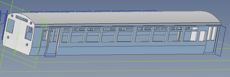
The roof is part of body, so no difficulty in trying to fit it. Fitting interior will therefore be a bit more difficult, but lesser of the two evils.
What scale is this?
-
LCDR buffers are now on sale again. The wagon buffers have been redrawn using original, LCDR GA-drawings and dimensions supplied by Geoff Lines, and are now vastly more accurate. There are also some coach buffers which would suit the D&S kits for the 6-wheeled coaches and the Roxey kits for the 4-wheeled coaches. I don't know if the LCDR used these buffers on bogie coaches.
https://www.shapeways.com/product/WZXXUYQEQ/lcdr-coach-buffers-x20?optionId=61158671
https://www.shapeways.com/product/9A22NAFSY/lcdr-wagon-buffers-x20?optionId=61074954
These are in first-to-try status at present, until I get my test prints.


GWR CLERESTORY COACHES - drawings
in GWR Rolling Stock: model and prototype
Posted
Hmm. When were the extra reservoirs fitted to the slip coaches generally? I have a vague memory that they were a retrofit on the Dean coaches.