


croydon junction
-
Posts
185 -
Joined
-
Last visited
Content Type
Profiles
Forums
Blogs
Gallery
Events
Exhibition Layout Details
Store
Posts posted by croydon junction
-
-
20 minutes ago, Richmond Park said:
Since my last update work commitments have prevented significant progress, nonetheless, the sides of the Underground ramp in what will be the scenic section have been filled in and the ramp is now fully braced

Before starting work on the scenic walling I thought I better have a test run. Unfortunately, testing of the S Stock on the ramps has revealed that the units are not keen on the gradient of the scenic ramp, even with the Bachmann supplied traction tyres fitted

The S Stock is ok with the gradient of the return ramp behind the fiddle yard which is less steep as built over a longer run. I think the answer is likely to be twofold; adding additional weight to each of the driving/motor cars to help traction and potentially altering the lower part of the ramp to make the gradient less steep

Locomotives with more weight onboard like the Hornby Class 60 are fine with both ramps. This isn't much use to me however, since the primary purpose of creating the ramp was to model the Underground which would be the domain of the S Stock. A frustrating setback but I'm not giving up on the idea yet!
Here's some pictures of the S Stock posed on the ramp to give you an idea of what I hope to achieve. In the image below, I will be looking to add terrace houses and gardens along the rear against the wall, with the National Rail tracks running in the area closest.

I know this might sound like a silly question but have you considered producing replacement motor bogies for your stock? If you knew your spatial constraints and dimensions, you could probably produce a bogie for a lower gear ratio which would give it the required torque to get up the ramp.
-
 1
1
-
-
out of interest have their trains come out of lockdown yet? And have they started building a high speed railway in the area yet?
-
On 04/08/2020 at 10:48, Phatbob said:
To go for a moment, The Northern CAF units lack one essential feature for any multiple unit, a corridor cab. I'm pleased to see that TfW have not been so negligent with theirs.
agreed, nice to see the new lnwr class 730's are going to be good for long distance services. Makes a nice change with the new bombardier units, they look like second rate spaceships
-
 1
1
-
-
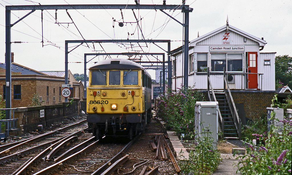
1 minute ago, Lacathedrale said:
Is the unit behind the brown one in LT red? I do like the cast of the photo - it certainly has that evocative tone of sizzling tar, heat radiating brick and dust.
by the looks of it it is. Think its F stock from the district by the looks of it
-
On 05/07/2020 at 18:24, simon b said:
So after alot of searching web stores I have some more brick sheets on their way, it seems due to the current situation all the usual suppliers had sold out.
I'm now thinking that some of Peco's OHLE would be a good addition to the layout, a class 90 or 86 hauled freight-liner is something I'd like to recreate.
you can easily scratchbuild/kitbuild your OHLE to suit the layout at a lower cost than any RTR ohle, and it would probably look much better as it was designed to suit the situation. You can get brass trusses here: https://modelshop.co.uk/Shop/Item/Brass-truss-2-5mm-11-lengths/ITM1920 to make twin track cantilevers, along with other building materials such as I and H sections. I recommend that the contact wire should be no thicker than 0.5mm, and that you go for one that can be soldered so it will be stronger. You can find brass or copper wire on amazon and ebay at about the right size without paying too much.
best of luck
Matthew
P.s. Clive Mortimore has loads of diagrams on this site for different types of OHLE, have a look around and that will give you an idea of what to build if you are struggling for dimensions
-
sorry to throw a spanner in the works, but here is another way for you have a station/industry layout. This would actually work for 00 gauge with your baseboard size, but it would be most suited to the southern region as you could use a 2 car EMU/DEMU. Brockley Green (EM gauge) used this setup, but was much larger.
Best of luck,
Matthew
P.s. your CAD pics look really good, what package did you use?

-
On 10/06/2020 at 18:54, acg5324 said:
A piece of memorabilia arrived this week
This is is a fingerboard from Clapham Junction for the 0625 Newhaven Marine to Manchester Piccadilly......a train that only ran for the 1986/7 timetable.
strange to think a train would run from Watford fast via the Trent Valley, exit the main 2 track route to manchester then rejoin! Must have been a complete nightmare for signalling though!
-
1
-
-
13 hours ago, Atso said:
A very belated thank you Jeremy!
It's been awhile since my last update. That's mainly because not a lot has happened regarding the layout itself. However, I've now started to build the next batch of track, but I am currently isolating at my other half's so it will be awhile until I can get access to the layout itself.
Otherwise, I've been working on four of the five carriages required for the Cambridge Buffet Express but have now gone about as far as I can go until I can get some more bits and pieces. The carriages can be found on my workbench thread (link in my signature).
Otherwise, I've been busy trying to work out compromises to some of the longer passenger formations that I would like on Hadley Wood. This issue isn't only length, but trying to find a suitable compromise between the running periods so that the Down and Up services are both plausible, despite the upgrading of stock over this period. This has been a time consuming but fascinating subject to research. This has however revealed the extent of the stock building programme needed for the layout. While not surprising, finally seeing that I've identified over 40 carriages but only eight of them can be produced using RTR items out of the box, is a sobering thought...
have a look here, if you have been able to get that far then the kit manufacturers on this page should be able to help you get most of the rest of the way: http://www.2mm.org.uk/links.htm
Best of luck,
Matthew
-
 1
1
-
 1
1
-
-
Out of interest, PN looks brilliant but with all this extra time in the railway room, have you thought of trying to build any extensions or anything? I know it would be very difficult logistically, but it might remove any monotony in current operations?
-
15 hours ago, donny rovers said:
soz
it can even be painted in Northern livery! In all seriousness, best of luck with the 325!
-
1
-
-
9 hours ago, petejones said:
Managed to get the track cut and roughly placed into position this evening. The first two shots are from last August when I made the baseboard (ladder frame with craftfoam inlay - very lightweight - I can lift this with one hand):


good choice of layout, not too simple or complex
-
1
-
1
-
-
40 minutes ago, petejones said:
Right, more ideas. This is just to put the sidings into context, so the following pic is what I will model:

And this is the site in full view. The lines merge into one off to the right (not shown):

very nice idea, but the idea of an inglenook is simple - have a shunting neck and 3 sidings, it is just meant to be a shunting puzzle. Having said that, you could have a platform edge for one of the sidings. Honestly, I think you have come up with enough ideas now, focus on how you can flesh out each option in low detail then take forward your favourite ideas.
Best of luck,
Matthew
-
1
-
1
-
1
-
-
9 hours ago, gismorail said:
How about a flood scene .........

knock over a beer glass... then again you might get short circuit problems
-
 1
1
-
-
2 hours ago, 73c said:
Would something like this be any good for a traverser?

There are other CNC fittings that will admittedly deflect more, but are much cheaper and will do a fairly good job. Deflections could be reduced by having a longer bar than required, and having an extra support at each end, pulling the bar down if loaded in the middle by the traverser
 .
.
Best of luck,
Matthew
-
 1
1
-
-
4 hours ago, thegreenhowards said:
Now that is a good question Clive. I’m always suspicious of one offs for that reason. I imagine they added a CL or two with a standard quad art, but who knows?
imagine that problem with the silver jubilee, the coronation and west riding limited weren't as bad as there was a spare set for them
-
1 hour ago, thegreenhowards said:
Today we feature the 1829 Welwyn Garden City to King’s Cross. This is the return of the 1706 Broad Street to WGC which followers of the thread will remember was hauled by NB type 2, D6106. The question is will it make it back?! And the answer is ‘no’. The driver failed it at WGC and the old order was dug out to haul the return including the errant type 2. So here we see N2, 69546 piloting D6106 at Gresley Jn.

I tried a new camera position but I don’t think it worked. The picture is rather back lit I’m afraid, so let’s say it was grabbed by an enthusiast who spotted the unusual working but didn’t have time to get to a better vantage point.
The more observant of you will spot a new station building in the background. This is the beginning of my attempt to ‘de-superquick’ the layout. This is a Scalescenes kit, but will be much more unusual, I hope, than its predecessor. Unfortunately I didn’t quite measure it accurately, so, because of the slope of the loft walls, it won’t fit in the old location without my trimming the Copula which would be a shame. So I’m going to wait for the second building and then decide where to place them.
In reality, rather than the NB Type 2 failing, it was a case of having tried the DCC consist function, I wanted to practice it again. This time it worked first time and both engines worked smoothly as I hope the video shows.
have you considered using plasticard and/or clay for the buildings?
Matthew
-
9 hours ago, bigwordsmith said:
A couple of months ago one of my Facebook Friends, a former client who is a real friend as well, shared this with me. I think it is very apposite to the discussion!

modernity in a nutshell
-
2
-
-
On 27/12/2019 at 07:54, Colin_McLeod said:
Enjoy your layout and if it satisfies your own needs and 'looks like' the prototype you are modelling then IMHO that's it. Anyway unless you have a enormous railway room some compression of dimensions is unavoidable.
Your thread title "How close to accurate do you need to be" reminded me of the one where a fitter was applying for a job in Harland and Wolff shipyard in Belfast. He told the interviewing foreman that he can make things accurate to within one thousandth of an inch. Sadly he did not get the job as the foreman informed him that was not good enough as all measurements had to be "dead on".
did they ever get the measurements dead on there? If not how far out were they, and how many of their boats sunk?
-
1
-
1
-
-
Best of luck, looking forward to seeing this layout progress! My only criticism is the track layout looks too reasonable, some of the formations in that time were ridiculous, Euston looked as if it had been blindly thrown together https://maps.nls.uk/geo/explore/#zoom=17&lat=51.5295&lon=-0.1372&layers=163&b=1 and the platforms from Ludgate Hill are a stones throw from Holborn Viaduct and Blackfriars https://maps.nls.uk/geo/explore/#zoom=17&lat=51.5132&lon=-0.1030&layers=163&b=1
Best of Luck
Matthew
-
Hi all,
I got a small cnc machine recently and have been struggling with the software side. The kit didn’t come with any software links, but has a CronosMaker control board directly connected to the computer via a supplied USB lead, and GRBL is recommended.
Firstly, has anyone got a link to GRBL as the Github page is a nightmare to find the actual download (I haven’t managed it). Secondly, I have looked on youtube to try and fix my problem and a USB driver was recommended. Does anyone know of any drivers that I need to install for this specific board, or do I need to install a general driver? The setup is shown below:
Many thanks,
Matthew

-
Imagine trying to motorise a 2mmFs Velocipede, you would have to get an ant to cycle on it
-
1
-
2
-
-
6 hours ago, Erixtar1992 said:
Cheers rich. They are worth the money.
have started laying the track now, made the decision to respace the sleepers. heres a couple random pics. Will update properly soon


good choice on respacing the sleepers, have you thought about making a jig as this could give much more consistent results?
Best of luck,
Matthew
-
26 minutes ago, thegreenhowards said:
Our photographer has moved to Welwyn viaduct now, the the next few photos are likely to be of that area. Today we have a brand new EE Type 1 on the ‘Ashburton Pullman’ - the rubbish train from Ashburton grove to Blackridge tip. This is the return empties. I don’t have the freight WTT so don’t know what time this train should run...it just slots into my sequence when I can be bothered to load its cassette.

The wagons are bogie sulphate wagons which were cascaded onto this train in the late ‘50s. I built them from Parkside kits.
And here is the video
Andy
it looks like a journey would be very scenic, how much would a ticket have cost?
-
1
-
-
On 02/12/2019 at 09:08, thegreenhowards said:
OK. Now we have the final stretch of the layout.

Here we have a general view down the layout with the K1 and the oil tanks crossing from the down slow into the freight loop across the second line of slips. The signalbox on the far side is the LCUT large signal box, but as yet is in a half built state. The coaling stage is Metcalfe and is more GW in outline (shock horror!) but Hatfield had one a little like this in LNER days so I don't feel it's too out of place - it does need some detailing though!

This is the diesel depot section with the coaling stage and turntable behind.

Here is the tunnel mouth leading into the fiddle yard with A3 'Minoru' emerging on the down fast. The tunnel section is based on the Gasworks tunnel exit from King's Cross with red brick on the far side, yellow in the middle and blue on the nearest section just like at King's Cross. The canal section should be set further back with a road in between, but I had to foreshorten it. The lock is there, but should be a few feet to the left.
As you can see only two of the tunnel mouths have track properly laid. Initially I intended that the final tunnel mouth would be boarded up, but I'm now considering extending platform 6 through to the fiddle yard to allow a branch shuttle to enter the station from the south. The loose track emerging from the tunnel mouth is the beginning of this extension. It will probably only be single track, as to put a double track in would mean moving a roof joist! The track plan would change from this:

To this:

The revision would allow the branch shuttle to run in from the fiddle yard, run round, and return. It would also allow up goods trains to recess and run round for shunting operations. I would assume that there is a connection back onto the up slow beyond the tunnel, so that goods trains can exit via the new connection.
I might also add a connection from platform 5, but at the moment, I'm inclined to keep it simpler, as the above seems to offer everything I need operationally.
Any views would be welcome.
Andy
nice to see the rest of the layout, that K1 looks really good on that crossing, really captures the ECML south of the Welwyn Viaduct pre modernisation. Here is a good video of that area:
-
3
-
1
-


 for a moment, The Northern CAF units lack one essential feature for any multiple unit, a corridor cab. I'm pleased to see that TfW have not been so negligent with theirs.


 .
.


P4 Temple Mills
in Layout topics
Posted
Hi Rob,
That site is used to store Greater Anglia EMU's. When they were building the Olympic Park, the island occupied by the ArcelorMittal orbit had some stabling sidings which had to be displaced, and I presume these were moved to Temple Mills
I hope this helps,
Matthew