

Harlequin
-
Posts
5,595 -
Joined
-
Last visited
Content Type
Profiles
Forums
Blogs
Gallery
Events
Exhibition Layout Details
Store
Posts posted by Harlequin
-
-
If the storage area is operated as carriage sidings doesn't that mean that, effectively, every train on the ECML has to terminate at and depart from Eastwood Town?
Or to put it another way trains can't just pass through on their way to somewhere else, Edinburgh, London or wherever?
-
1 hour ago, gordon s said:
Apologies for not getting back before now, Phil. I've just sat and watched Alex Salmond for six hours on TV. Found it riveting and all credit to him, he didn't hesitate or bluster on any answer for the whole time. Fascinating....
OK ET....
Thanks Phil, for taking a look. Here's my take on what you are proposing. Ignore the storage lines down the middle, but I assume you are suggesting taking the storage from point A on this plan.
There is space behind ET station to run another line particularly one that is descending. I'm assuming the new line will replace the existing one that starts bottom right. It would have to use that space as there is no room at all next to the side wall.
Next thing to overcome is the board structure itself. I don't think I have shown this before, but the main frame is 90mm x 20mm planed timber. The track bed is raised 82mm above that and the trackbed is 12mm.
The total depth is 184mm and say you need a minimum of 200mm clearance under the timber frame. You're now up to 384mm, which at 1:100 is going to need 38.4m run. I can't go any lower than the top trackbed over the stairs as it will clash with the hand rail and I'd get shot if I cut some of that away. I've only just been forgiven for this and this was 2007.....
At that rate, I'd need to go round the layout twice to find a 38.4m run.....
")
The other problem is anti clockwise trains which at present can cross the main lines into line 7 and then be shunted off into storage. With a downslope line on the outside, it just adds more complexity for trains to access the storage as they can no longer use line 7. Great if I could have both as that would work, but there is only room for one line next to the stairwell wall.
I'm open to any suggestions, but really have a hang up about anything hidden from view, particularly a 15 road storage unit where trains cannot be seen and mechanically I now realise it can't be done, but many thanks for looking at it. I take a more in depth look at cassette's over the weekend to see if they provide a solution.
I can see your extra deep baseboards do make any lower levels quite tricky. And yes, I agree that anything hidden is to be avoided if at all possible.
But in the end you might decide that some partly hidden solution is a price worth paying to keep the middle of the room open and all parts of the layout easily reachable.
For the record, I was thinking of two possible alternative junction positions:

-
It's good to have a light source that casts definite shadows more like the sun than most layout lighting rigs but I must admit that I find most of the recent photos (I guess with the builders lights) quite harsh. Are the two things linked? I don't know.
(More "noisy" in the digital photography sense of the word, perhaps).
-
Hi Gordon,
Thinking about your storage problem: (Bear with me...)
If you took the storage access line off your main lines outside your station entrance crossovers you wouldn't have any problems with wrong road running because traffic could just cross straight over immediately. You'd then need more distance to achieve a shallow gradient so...
Could you run the storage access line right around the outside of the room, behind ET, descending as it goes, obviously. You might have to notch or reconfigure some supporting framework and it would go through the stairwell, I realise, but it would be against the wall, where it wouldn't get in the way (I think).
Then turn back under the scenic area (plenty of clearance by now, at least 150mm at 1:100) and either emerge into the operating well or possibly, if the clearance is sufficient for access, run under the scenic area between the support legs.
If you can get the storage under the scenic area that would be great because you could use the existing framework to support it and it would keep the operating well clear - but it depends whether it's accessible enough down there or not...
-
 1
1
-
-
1 hour ago, RichD1 said:
The board with the river on I was planning on making that one about 50mm deeper than the rest. The tops would then be all at the same level and I would have a 50mm dropped area just where the bridges are shown to make a river and embankments.
Just trying to work out a materials list and have found a great optimiser website. https://cutlistoptimizer.com
Also checked out birch ply pricing and its quite expensive now! 4mm @ £44, 6mm@ £47, 9mm @ £54 and 12mm @ £61 per sheet. So just for the tops in 6mm the Optimiser tells me I need 4 sheets and for the 4mm frame work I need 2 sheets. That makes a total of £276 just for the ply. I'm not sure if birch is worth the extra as when I went to look at it on the racks the sheets were still not that flat/straight but I guess better than Far East stuff.
Do you think I would have a problem using cheaper ply if say I use 18mm ply ends and the sandwich construction of 4mm ply spaced with softwood blocks for sides and crossbeams. Would everything hold square bearing in mind I do have a large mitre saw to cut ends very square.
Richard
I've used Builder's Merchants "hardwood" ply a lot and it's been fine for me. E.g. Travis Perkins, Jewsons, etc. Your mileage may vary.
(Check the sustainability of whatever material you use, though... That becomes ever more important!)
Here's a blog entry from when I was making open frame boards a while ago: https://www.rmweb.co.uk/community/index.php?/blogs/entry/20645-test-track-baseboard-construction-pt2/
-
2 minutes ago, Happy Hippo said:
Have you thought of using closed cell foam as a structural materiel?
You just use ply to protect the edges.
Would that allow the joints between boards to be accurate and rigid enough to align tracks that are curving, angled in XY and on a gradient (i.e. angled in Z) where they cross the join?
-
4 hours ago, RichD1 said:
Thanks Harlequin for your response. Would a lattice be the best approach or just straightforward crossbeams. Most modules would be about 1 to 1.2 metres long so would have about 3 crossbeams plus the 2 ends. How would you construct a lattice?
I was also thinking that the ends of the module would be substantial thicker to provide the stability and alignment for the dowels and scenery above. Was thinking about 18mm but this is maybe an overkill.
So considering a module with a raised section I would make a piece that fits the top of the whole frame then mark where the incline track would be and then saw this out and put on top of the risers to form the trackbed?
Yes, more or less.
4 hours ago, RichD1 said:I was thinking of using the Woodland Scenics incline set so the boards in this area would be flat and then when it gets to the top of the incline would then go with the ply risers round to the Terminus at the top. Alternatively I could use Woodlands riser sets all the way round. I am hoping to have at least 2 bridges/viaducts in it on its way round to the top so the Woodland foam risers might not suit.
I'll try and sketch out a track plan so you can see what I'm trying to achieve.
Richard
"Lattice" / "crossbeams" - pretty much the same things. I only call it a "lattice" because it's all ply and an integral part of the baseboard unit.
You could use the woodland scenic risers but in my mind they wouldn't quite fit with a modular open frame baseboard system because:
- One of the advantages of the open frame is that you don't need to cover the baseboards with a ply surface and the woodland risers would need a surface under them as well as a surface on top. (You need the surface on top at least at the joints to hold the track securely.)
- Since you have baseboard joints with solid risers quite regularly spaced, change to the woodland risers in between seems overcomplicated - may as well just use the same type of risers everywhere.
In your plan, I notice you have a river flowing under the main line, which is great. The main line around the point would be on risers above that particular baseboard frame and if only that baseboard is lower then the rest the joints might be more tricky. So to allow for that you might think about effectively lowering all the baseboard frames so they join together easily all round and have the entire main line (and the station area) on risers all the way round. That's not as mad as it sounds - it allows you to drop the scenery away from the track wherever you want, getting away from the billiard table effect.
-
17 hours ago, SteveyDee68 said:
... would the "sliding water cover" operate as a 'consist' with the ship to ensure movement is perfectly matched? The ship itself would need water modelled at the sides fir it to sit in, to move off with it and allow the sliding cover to replace it (easily hidden under the enclosing dock walls on both sides of the ferry berth). To disguise the join between ship water and cover water, do you model the wash/wake/turbulence at the rear from the ship's propellers? (This would perhaps look odd when reversing into the dock, but would be hidden under the link span when berthed.)
You're over-thinking it...
 The water cover would be operated by gravity. It could be shaped at the ship end to wrap around the bow/stern of the ship(s). It would roll in when the ship leaves and just get pushed aside when the ship docks.
As far as wash is concerned, you could probably paint some light turbulence on so that it looks vaguely right in all conditions, maybe? But it you really wanted to go for it, maybe it could be animated in some way - er, a skinny edgeless LCD screen showing a video??? Now I'm over-thinking it!
-
 2
2
-
-
On 24/02/2021 at 00:15, Ray Von said:
They are manually operated, brass rods.

Someone suggested that it might be useful to use levers to reverse the motion of your rodding...

-
 1
1
-
-
Hi Steve,
What if the ships were themselves on rails and run from your normal train controller, ideally DCC.(Yes, I said ships...)
Having loaded the ship that’s docked, you raise the ramps via DCC. That alone may be enough to hold the stock in place but if not then you actuate some other clamping mechanism like David’s magnets.
Then you gracefully drive the ship off scene, into a “ship fiddle yard” where there is, cunningly hidden, another ship with alternate stock on board.
To hide the rails while no ship is docked there’s a section of “water” that also runs on the ship rails and slides into place from under the quayside.
Sometime later you change the points in the ship fiddle yard, sound the ship’s horn (did I mention that the DCC ships on rails are sound fitted? Of course they are!) and drive it on scene to the amazement of the audience. The new ship pushes the sliding water cover back under the quayside. Release the stock clamps, lower the ramps and haul the new stock onto the layout proper.
While either ship is off-scene you’ve got the opportunity to shuffle the stock on board by hand if you want to ring the changes.
Could be automated in exactly the same way as you would automate your railway.
-
6
-
 3
3
-
-
Yep, so just to be clear, some of the joints must connect sections of the branch line while it is still on a gradient.
This is more difficult to engineer reliably than level joints but should be do-able if you make very stable structures with tight and accurate fixings between them.
You might consider open-frame all-ply or nearly-all-ply construction for these units. That method is lightweight, strong, and allows easy variations in height of trackbed.
The basic principle behind all-ply construction is to use ply pieces joined perpendicularly, usually glued, so that each one straightens and braces the other. You basically form L beams, I beams, T beams, H beams or in extremis box girders from the ply. This works well if you can cut clean dead straight pieces, and it sounds like you can. The straight edges naturally take out any warping in the pieces fixed to them.
The open frame means that you can a lattice of cross pieces, where you can fix flats for level track bed but also from which you can fix risers up to your inclined track bed. Imagine that your track bed has ply risers from the lattice below controlling the level or the gradient Then fix reinforcing pieces under the trackbed perpendicular to the risers so that if you look at the trackbed in section you see a T beam. That should be hugely strong, guaranteed not to droop, very stiff and yet relatively lightweight.
The choice of ply thickness is a trade off between weight, number of parts you have to make and the frequency at which you need to support your track bed. 4mm track bed would need a lot of support, whereas 12mm would need much less but would be heavier and more expensive.
6mm or 9mm is probably about the sweet spot.
Use alignment dowels at the baseboard joints to get precise, repeatable alignment. That's one place where you may need the extra thickness provided by some PSE timber to stiffen up the structure and provide depth for fixing the dowels.
-
2 hours ago, AndyB said:
Looking good Phil.
May I ask what size the grids are. I'm trying to imagine those in comparison to a OO coach. Or 5 coaches and a loco to be precise, and whether view blockers in front would be beneficial.
305mm grid. (1 "metric foot")
-
 3
3
-
-
Not much change on this plan, I'm afraid. I have been working (very slowly) on Minories.
I have drawn a more balanced curve, with wider radii in the scenic area (red):
I need to make templates for OO-SF turnouts and work out how to curve them reasonably.
I had an idea about the fiddle yard: Since it's in the living room, and since lots of stock will be standing in it that needs to be protected from cats, dust and general knocks it would be a great if it had a glass (or acrylic) cover. Practical and an attractive display cabinet of sorts.
-
3
-
-
Hi John,
It all sounds very exciting!
Is this topic morphing into a Layout Topic, not specifically about electrics any more?
-
8 minutes ago, The Stationmaster said:
What existed at Bath was a common arrangement on the GWR which at one time existed at numerous places and was basically a double ended siding connected at each end to a running line by a trailing point. Reading, I think probably had the last example although its use had changed enormously over the years. All the three track bits of running line on the Western which I can think of were strictly uni-directional for the third line.
Could the central siding of the type described have been used to allow passing by having the train ahead setting back into it, assuming it was not used to hold rolling stock?(BTW: A bi-directional central loop, as the OP imagines it, would need facing points at both ends, signalling and multiple FPLs so quite a complex and expensive bit of infrastructure. In fact, quite expensive in terms of space in a model too...)
-
-
Some interesting discussion of voltage spikes on DCC systems here:
https://sites.google.com/site/markgurries/home/dcc-problems/decoder-problems/decoders-blowing-up
The author suggests that it’s an issue on busses longer than about 10m during short circuit events and is caused by inductance in the track bus.
He suggests twisting the track bus wiring (and explains why and when to do this in some detail) and/or fitting an RC snubber.
-
Hi everyone,
I realised yesterday that I may have made a mistake... I concentrate on interwar GWR and I have pre-ordered 7808 Cookham Manor in shirtbutton livery. OK, so at least I got the basics right, she did exist pre-war and she has the right livery, but I gather that the model represents her in preserved condition, very much post-war.
So my question is, what are the visible differences in Cookham Manor as preserved and in pre-war condition? (Chimney???) Or to put it another way, will the model pass on a pre-war layout? Or to put it yet another way, do I need to change my order?
-
1
-
 2
2
-
-
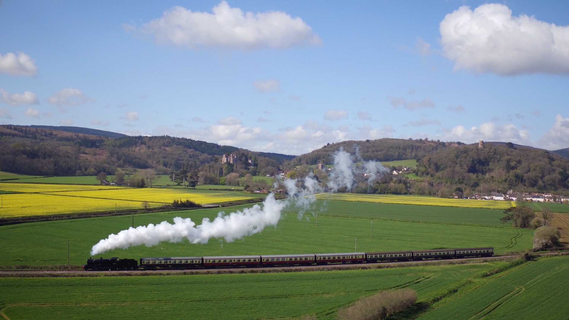
Dunster for Dunster Castle.
-
5
-
-
Are you sure the your problem is caused by the wheel tread? The most commonly documented problem with the unifrogs is when a wheel flange touches the rail behind it near the insulating gaps.
There’s a simple fix for that problem that it might be worth trying before modifying the turnout or the loco (assuming the back-to-backs are within acceptable tolerance): paint nail varnish on the inside of the rails near the insulating gaps, not the rail surface, to prevent the wheel flanges making electrical contact.
-
1
-
-
16 minutes ago, Hamburger said:
If the loco has a built-in flicker device that flickers with DC and you add a decoder with the output also set to flicker, this can lead to brightness problems.
Good point, thanks.
I just checked my model and one of the two outputs controlling the firebox (from the same Function key) was set to random flicker. Changed it to simple on/off. No discernible difference.
It would be great if there were a simple config tweak to make the firebox brighter but I fear that the only way to overcome the fundamental design problem is to modify the loco.
-
1
-
-
2 minutes ago, RobinofLoxley said:
Not what was seen on the review - my memory escapes me but it was a very well-known reviewer
I guess it might have been DC control in the review?
I'm just reporting what I observe on my model under DCC control.
-
1
-
-
Under DCC control the flicker doesn't vary with loco speed, of course.
-
1
-
-
Obviously there's far more to making your own turnouts than simply filing and soldering. There are all sorts of technicalities that Wayne's kits will (should) deal with, removing the burden from the buyer.
For instance, I refer you back to the deeply technical discussions above about exactly what sort of chairs to use in what positions and how to angle them.
-
4
-
 2
2
-
")


Little Muddle
in Layout topics
Posted · Edited by Harlequin
Wash Common and Enborne feature in my family history and railway history: Enborne was the birthplace of Albert Pibworth, "Old Pib", who was one of the drivers on the famous first non-stop Flying Scotsman run to Edinburgh. He also took part in the 1925 exchange trials, driving an A1 pacific on the GWR. In retirement he lived at Wash Common and is buried in Enborne churchyard.
https://www.rmweb.co.uk/community/index.php?/blogs/entry/22886-driver-albert-pibworth-on-the-gwr/