

RLWP
-
Posts
429 -
Joined
-
Last visited
Content Type
Profiles
Forums
Blogs
Gallery
Events
Exhibition Layout Details
Store
Posts posted by RLWP
-
-
8 minutes ago, 34theletterbetweenB&D said:
How do I know this? Because the leading crankpin will foul the combined cylinder/slide bar.
Are you sure about that? To me it looks like a very long piston running in an even longer cylinder. At the end of the stroke a lot of piston is sticking out of the bore, you can see the change in colour of the materials
Not a bad way of getting a big bearing surface for the oscillating piston
9 hours ago, The Johnster said:So it does, well spotted. This presumably means that both cylinders oscillate in unison with each other. This sounds disastrous for stability.
It’s an odd little beast altogether, isn’t it, and from such one can often learn unexpected lessons. And I have to endorse the opinion that it’s designer and creator deserve muchos kudos!
If it can be made to work, I’d be at least as inclined as the cylinders to replace what I think might be missing coupling rods, which I think might improve the running and reduce the likelihood of slipping. I can’t make out on my phone screen if the wheels are flanged, or what gauge (if any) (well it must be some gauge, but you know what I mean) it is, but if it’s LGB it should run on that track.
There's a fundamental problem though. With an oscillator you only get a push from the piston once per revolution. With a two cylinder engine, it makes sense to time the two pistons at 180 degrees to each other to equal the pulses. But you can't 'quarter' connecting rods at 180 degrees, they will overcentre and lock (as I found as a kid dismantling Triang locos)
You could quarter the wheels and accept an uneven 'puff'
Richard
-
 1
1
-
-
To be honest, if it works I would leave it alone. It is never going to be an accurate representation of anything, so it is what it is
No matter how it looks, if it does work whoever built it deserves some respect for making an operating steam engine
Richard
-
1
-
 2
2
-
-
5 hours ago, The Johnster said:
Interesting project; I have no idea what it is but it looks sort of European. It's very crude and toylike, and I'd imagine it to have been a mass produced item somewhat like the Mamod locos. I can't see that whoever designed it had ever had much to do with actual steam locos of any sort. There is what looks like a crankpin on the trailing driving wheel and it may have had a coupling rod at one time. I'm guessing that there are exhaust steam pipes leading from the cylinders to the chimney, but I'm not sure there's a smokebox in the conventional sense of the word.
My attention is drawn to the soldering that fixes the cylinders to the frames. The cylinders are probably not as long as they look, extended into a tube that acts as slide bars, but they may have been originally oscillating like a Mamod's, and altered to be fixed by someone. This may have been because the oscillating cylinders made the loco unstable when it was running.
Just random thoughts, I'm no expert in this sort of thing.
They still oscillate, notice the backplate is sitting at an angle to the brass 'frame'. You'll probably find it exhausts straight out under the front running board
Clearly the builder had a big box of brass cheesehead screws
Richard
-
1
-
-
502 errors here, View New Content searches take several seconds, 'storing' posts takes many more
Chrome 73.0.3683.86
Windows 10
Richard
-
 1
1
-
-
2 hours ago, raymw said:
It's very slow 4 me, using firefox. To the extent of almost unusable. Not tried other browsers
Slow for me on Chrome, and occasionally times out with a (from memory) 502 error. It's been like that ever since the upgrade
This probably belongs in a different thread
Richard
-
2
-
-
6 minutes ago, Boris said:
For protecting staff working in buildings, or in the case of severe gradients to stop vehicles wandering off down the siding on their own if the handbrakes aren't applied correctly etc. It's no different than remembering to apply a handbrake, chock or sprag stabled vehicles, reset a hand point or many other things the shunter has to remember to do because its part of his job.
So, does it comply with "Safety Points - worked scotches or derailers may be used in instead of safety points where protection is necessary." ?
It sounds like a piece of shunters safety equipment, not a piece of signalling equipment
I'm not denying it's usefulness in a shunting yard, it clearly would do what is intended of it. I'm trying to work out if it would satisfy the BOT if it is not somehow interlocked.
I'm not expecting point rodding or some kind of positive link to a signalbox, perhaps a key to unlock it that can only be released when a set of sidings is isolated from a running line
Richard
-
If he has to remember to drag it back, what's the point of having it?
-
On 18/03/2019 at 14:14, micknich2003 said:
Wheel Chock, Beverley Cherry Tree, June 1983.


How is the use of that controlled? The other derailers are obviously linked to a signal box, I can't see anything on that, not even a padlock
Richard
-
6 minutes ago, stephi said:
Thank you Richard
")
I hope, one day to be able to model this loco in the most accurate way possible
"in the most accurate way possible" is an interesting idea. As there is so little information, you could do almost anything within the dimensions of the very few drawings, and it's unlikely anyone could prove you wrong.
Or you could do a huge amount of research about early locomotive design in general, and for Crewe specifically, and still end up with something that it is unlikely that anyone could prove you wrong (or right!)
Did you make any progress @Killian keane ?
Richard
-
The mechanism ringed looks like the lifting links for the valve gear
Locomotives of this era rarely had brakesRichard
-
1
-
4
-
-
I usually order the NEM pocket couplings now. The 'lump' that goes in the NEM pocket is formed by folding the coupling shank over a couple of times. Therefore the unformed shank seems to be longer that the other kinds of coupling
I find the longer shank more adaptable for the various projects I do
Richard
-
15 hours ago, The Johnster said:
guards took yesterday's newspaper with them
So, that's the answer to the Rolling Stone's question
-
 1
1
-
-
A couple of locos come to mind.
The LNWR 4' tank:
sold to Kynoch Ltd, Witton in 1919 and now preserved
And probably the most famous:
.jpg/800px-Rocket_Tyseley_(2).jpg)
https://en.wikipedia.org/wiki/Stephenson's_Rocket#Service
Richard
-
2
-
-
26 minutes ago, Ruston said:
The diagram isn't exactly to how the layout is but the gradient is 1 in 18.
That sounds better, I was mislead by the diagram
So, have you decided how to signal your railway?
Richard
-

I'd say, compared to the gradient to get the quarry line over the other line, signalling is going to be a small problem. Have you worked out the gradient?
-
24 minutes ago, The Stationmaster said:
As an Inspecting Officer said to me at one preservation site over 30 years ago 'you realise of course you could have done all this with three ground frames and no fixed signals at all'
In 1878, the L&NWR worked the whole of Kenilworth station with a single seven lever ground frame. It was similar to this arrangement in that Lockharts Sidings (to the brickworks) was included in the scheme
No signal cabin of course - the L&NWR didn't spend money if they didn't have to
Richard
-
37 minutes ago, Nearholmer said:
The way I read it, the quarry siding starts ‘inside station limits’, so needs no signalling, and the CP gives adequate trapping.
Out of interest, where would 'station limits' begin on the 'L&Y' end? Presumably far enough up the line for the whole of the quarry train to be inside while waiting for the quarry road to clear? Or would you hold the quarry train outside station limits until it's road is clear?
Richard
-
34 minutes ago, Nearholmer said:
I think I can convince HM Inspecting Officer that it is fit for purpose, given the low speeds and infrequent service.
Take him to the pub first
-
26 minutes ago, bécasse said:
There is absolutely no need for a signal to control the exit from the quarry (but only because it is a light railway). The idea that a quarry train driver could run out in front of a non-stopping passenger train is absolute nonsense, quite apart from the fact that he would have to be in possession of the token/staff to come out onto the running line, the catch points would derail his train (hopefully away from the running line).
Which introduces two new things. The quarry train must stop to collect a token - how is that made to happen?
And I like the 'hopefully'
 . Let's hope the derailed train (not just a single wagon) doesn't foul the passenger line
Being serious for a moment, I'm always amazed how real world signalling can be both complicated (to make sure it is safe) and simple (like using Annett's keys to unlock everything). Actually, an Annett's key would be a neat solution to the quarry line
Richard
-
14 minutes ago, Ruston said:
The driver has to stop before the catch point anyway, so a stop board will suffice. He's opposite the box and within shouting distance and so the signalman will change the points and shout and wave a green flag when it's safe to proceed.
Too uncertain. The quarry train driver just misunderstood the green flag and ran out in front of the non-stopping up passenger train. He's been arrested for manslaughter
There really should have be a starting signal to control exit from the quarry
Richard
-
Just now, Ruston said:
So, just one signal at each end of the platform? That would suffice for trains leaving the loop from either track? IAt the RH end is the terminus station, with goods facilities but also other industrial concerns with rail connections.
How would a train from the quarry know it was safe to proceed?
Richard
-
I've just finished making some vans based on the Campbeltown & Machrihanish brake vans:

There's a drawing in Don Boreham's 'Narrow Gauge Railway Modelling' book
The grey vans are based on the drawing, the black vans are a shortened version

They're made from 0.010" styrene sheet:

with Peco wagon chassis:


Richard
-
9
-
4
-
-
3 hours ago, Killian keane said:
Very similar to SER nos 81/82/83 one of which is the subject of a new build
I didn't know about that project. From their website:
Quotethe construction of a working replica of locomotive number 81: the first of three designed by Thomas Crampton for the South Eastern Railway and built by the Whitehaven firm of Tulk and Ley in 1847.
So, could be identical!
http://www.cramptonlocomotivetrust.org.uk/
Richard
-
Halfords grey primer, and ask critics to prove you wrong then

Richard
-
2
-
5
-


")


 . Let's hope the derailed train (not just a single wagon) doesn't foul the passenger line

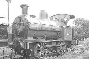
Unidentifiable Live Steam Engine
in Modelling Questions, Help and Tips
Posted
Plastic wheels?
Richard