


davegardnerisme
-
Posts
52 -
Joined
-
Last visited
Content Type
Profiles
Forums
Blogs
Gallery
Events
Exhibition Layout Details
Store
Posts posted by davegardnerisme
-
-
Would it have been worked from the signal box, or from a lever on the end of the sleeper?
-
My layout has a private siding. I’ve recently been installing point rodding and it got me thinking.
In my era (early 60s) this thread suggests gates would probably exist, but be left open and in disrepair.
Someone also suggests the trap point would be part of the private railway.
I was imagining it would make more sense for it to be part of the main railway, because then the signal box retains control over it directly... eg I was going to run a point rod to it.
So my question is: does it sound reasonable to have a private siding, where the trap point would be before the gate (and hence still part of the main railway), and have that trap operated from the signal box?
-
My BLT has a small goods yard, which splits into three sidings via a three-way turnout (all within the yard). The turnout that gates entrance to the yard will be operated from the signal box, but the three-way turnout within the yard will be operated from a ground frame. Photo below. Track plan on last post of this thread.
Question: are two levers enough (one for each "turnout" within the three-way)? I have read about facing point locks elsewhere on RMWeb, but I'm not sure if they apply to my situation.
Thanks

-
Ok so now the bit where I need help.
I'm trying to define two things. Firstly, I want to design the point rodding. My plan is to use Wills kits and similar to add cosmetic point rodding / signalling pulleys. The question is what path should these rods take? I've started with the signalling design from my other thread:
And I've adjusted it (because the design isn't quite the same), and I've drawn in the rods (blue lines) and wires/pulleys (ping dashed line). I've also noted where things are attached to ground frames. Does this seem reasonable? NOTE: in the picture below I've stitched together two photos (fairly badly) and then drawn over the top ... the track is fairly smooth and free of kinks across the two photos (here it looks a little angular).
The second thing I want to decide is how the goods yard will be laid out. In the picture above, the green tracks are not glued down yet, just balanced on top. Everything else is glued already and can't be changed without much faff (I have no appetite to change). For the goods yard, I've reused a three-way point, pretty much just because I already have it, so it saves me buying an additional turnout. I'm not completely opposed to doing so if people think it would be better.
In my design, I was trying to think through how the sidings would be used. I was imagining maybe a goods shed on the top siding, the middle one would be for unloading, and perhaps the bottom one would be to collect empties ready to send back the other way. Does this sound in any way sane? Any other suggestions?
@Nearholmer has a great suggestion that maybe one of the sidings could be partially lifted to add to the overall idea of dilapidation/disuse. I was thinking maybe the goods shed siding (and I think someone else suggested there could be a suggestion that the goods shed had at some point burned down -- perhaps just a light scorching on the ground). Regardless, the track would still have to have made sense at some point, and that's what I'm interested in here.
Thanks in advance for any suggestions. I enjoy reading and learning from the experts on RMWeb!
-
Some months on now, and I need help with the goods yard, and point rodding design.
But first, a quick update. In the last few months I've been slowly working on the land form, track laying, point motor wiring, and building the odd thing. Firstly what will hopefully end up as a dilapidated barn:
Not in intended location yet, but with roof:
Secondly I've started on the main bridge, which I need to help me figure out the landscape contours:
And again with a bit more work and an undercoat:
-
 2
2
-
-
Back in the early 90s I inherited track and stock from my elder siblings (when they left home; I was a few years behind them).
They helped kickstart a layout which was, sort of, a BLT I guess.
Things I remember:
* making buildings out of Linka .. eg the shed visible in first photo
* someone once gave me a cardboard model pub which took pride of place .. I remember it seemed to fantastically detailed to me at the time (I didn’t construct it)
By a stroke of good fortune, my Dad recently dug out these photos of it!


Now building a layout for first time in nearly 25 years, most of which was @Harlequin’s design ... as I have noticed seems to be de rigueur on this forum!
")
-
1
-
 1
1
-
 1
1
-
-
Talk of exchange sidings has brought me back to the private sidings design. I'm trying to add more detail to the design so that I can spend time creating the buildings. With the space I have available, this is achievable to fit around other commitments, but I do need to figure out what size they need to be.
So far I've got this:

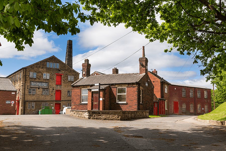
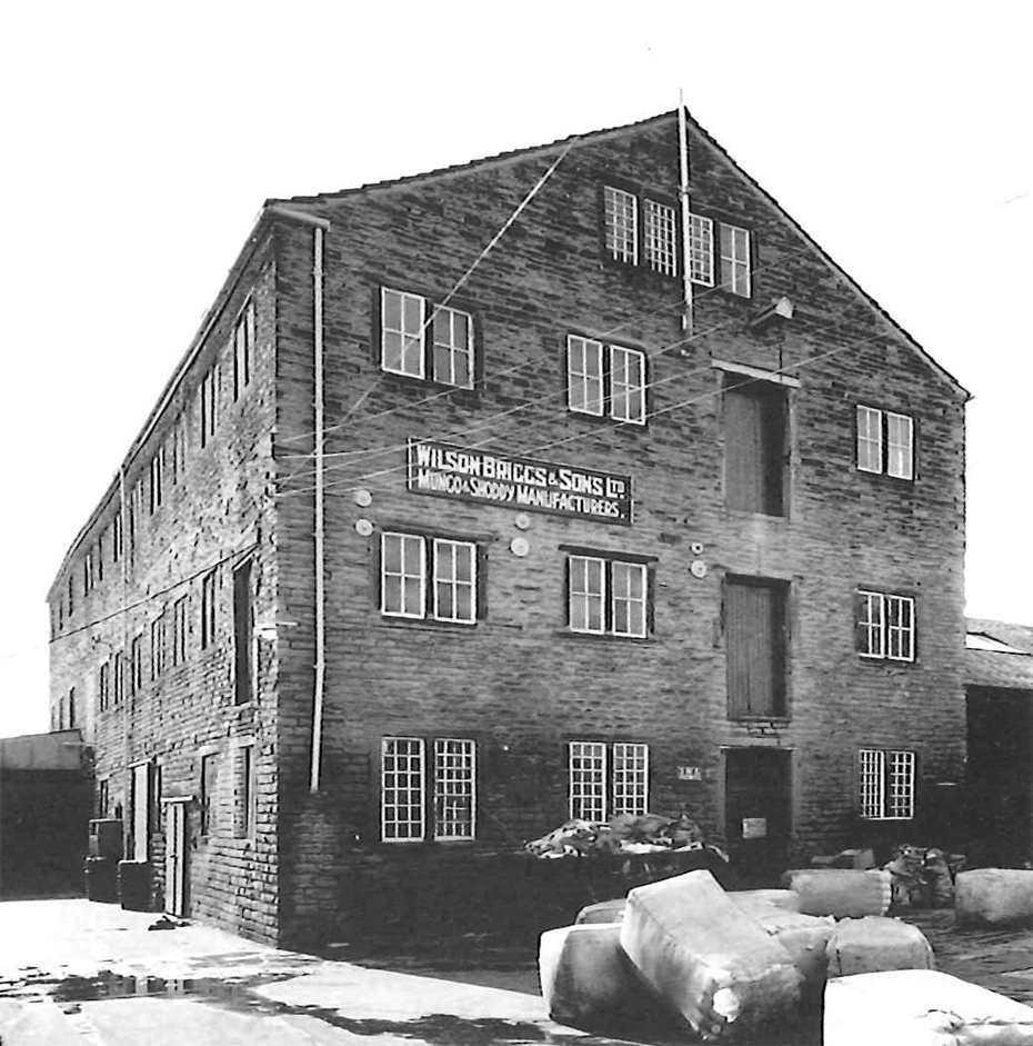
I've been collating inspiration here. I think this terrace would not look out of place behind the station building, and I like the mix of stone and red brick used at Healey New Mill (plus a photo from its heyday).
Keen to hear alternative suggestions for the private sidings ... I have been trying to think of ways to make them appear part of a larger private railway, but I don't think I've cracked it.
-
21 hours ago, Harlequin said:
Hi Dave,
The kink happens because the trap and the other short bit of track widen the spacing between the platform line and the run round loop and then you are trying to bring them back to the normal spacing very quickly. It's a difficult problem to solve nicely with Peco fixed geometry and since the signalling thread reckoned that the trap should bring vehicles to a halt clear of the main running line, and that it was perfectly acceptable to use a double slip to form the trap, that seems far and away the best solution.
Agreed. I played with it for a while but in the end I went back to double slip and it was much easier to make it work nicely.
21 hours ago, Harlequin said:To make the run round loop longer:
Push the loco release crossover as far left as you can and use the smallest radius points you can. Small (2ft) radius should be fine because, again, long vehicles are never going to traverse that crossover - and certainly never propelling each other.
The loop is fixed now. It’s a little shorter than it could be, but not enough to make me want to change it. I think at some point perfect becomes the enemy of good. I’m keen to keep pushing forward.
21 hours ago, Harlequin said:You could move the right hand end of the run round loop across the river but I don't think it would be very useful because the platform and and goods sidings impose limits on sensible train lengths. Making the run round loop longer is nice but becoems more of a luxury than a necessity.
Agreed. I mocked it up (loop crossing river) but it just didn’t look right. There wasn’t really enough track then that wasn’t in the loop! I’ve stuck it all down now.
21 hours ago, Harlequin said:The platform length is limited mainly by the position of the crossing into the mill yard. By connecting the mill line into the run round you are forced to use a long diamond and that in turns means it has to be further left to get good separation between the yard and the main line. That limits the platform length.
Hopefully it won’t look to short when it’s all done. We shall see. It’s all fixed now.
21 hours ago, Harlequin said:I think it's possible to make the Mill railway more operationally independent and more interesting if you want.
Yes! This is an area I’m interested in exploring. I’m inspired by some of Chris Nevard’s dioramas and small layouts. Eg
I’m thinking I could design a mini layout within an layout, perhaps with rails disappearing off scene. So far I’ve not fixed any of this line.
21 hours ago, Harlequin said:BTW: You really do need to think about your fiddle yard as well before you go much further because it affects how and where the main line exits the scene.
I’ve sort of already got this set (see pics below). Maybe I need to rethink. I was half thinking the fiddle yard board could be another 1m board, perhaps with some scenery and the tunnel entrance, to stretch everything. Not sure though. It’s already pretty big for my house (and no real permanent home for it, yet).
So my next steps are, I think
1. Sort out basic contours of the landscape and decide more concretely where river will be and mill sidings bridge.
2. Try to plan roughly where the buildings will sit within the landscape - perhaps doing full size mock ups of them.3. Plan the mill private railway (I guess this will be in conjunction with 2)


-
3
-
-
1 hour ago, The Stationmaster said:
One question - why is the runround release crossover so far from the stopblock end of the platform line? Have I missed something?
It is probably too far - although I think probably only 8cm or so from where it should ideally be.
There is no reason for this. The excuse is lack of attention when laying and glueing the track!
-
1
-
-
Hi everyone
Some progress has been made! Most notably I switched to code 75 track, and started laying the track including point motors. This involves some of the mods that we talked about on this thread - eg trimming turnouts to bring the tracks closer together.
I kicked off a thread on the signalling thread to work out how I should be signalling the layout.
I now have a couple of layout challenges that were highlighted when discussing signalling, and stemming from actually arranging the track on the boards.- The loop seems small (observation from signalling thread)
- The track work around the three way point is a bit tight, and there are some kinks that might need ironing out
Here's some pics.


It would be great to get thoughts on what I think are my options:
- Live with it (short loop, slight kinks)
- Swap three way for double slip again (avoids need for separate trap and therefore probably irons out some kinks .. but doesn't increase loop length)
- Move the first turnout to the other side of the bridge, extending the loop and making the main bridge a double track bridge (this potentially avoids kinks and makes the loop longer .. but does it adversely impact the balance of the layout and the mill sidings feature?)
NOTE: the first board track is stuck down now, the second board is still moveable.
Thanks
-
14 minutes ago, Nearholmer said:
I know that everyone loves to use software for track-planning these days, but can I put in an appeal, or perhaps simply a reminder, about more traditional, but sometimes dare I say it, better methods:
- pencil and paper, once you "get your hand in", is a perfectly fine method; and,
- good-quality masking tape is the perfect way to lay virtual track in a case where you already have baseboards made and are at the "fiddling about to get it perfect" stage. It works very well as flex-track in conjunction with full-size paper templates of points (stick the point in a scanner, if you have points and scanner to hand), but you can manage without the templates if you know the leading dimensions of the points (e.g. from Peco catalogue or website). you can then "play trains" with your actual rolling stock, before committing to fixing the track down.
Personally, I find that learning the quirks of sotware takes so long that pencil, paper and masking tape are quicker, but then I'm possibly an old fogey.
Agree -- I think I'm done with software. It was useful to get going, but now I'm at the making it feel right stage, and perhaps due to inexperience the only way I can really do that is by putting actual track down where it needs to be and then sliding coaches up and down and generally looking at it.
I will jump back to the other thread this evening (in Layout section) to request more advice about the key challenge of the runaround loop!
-
1
-
-
2 hours ago, clachnaharry said:
The shortening of the loop is mainly due to your moving the loco release crossovera long way back along the platform. What is your intention there?
It just sort of ended up like this!
However it's not clear to me it buys that much space. With buffers in place, perhaps I could get an extra 7 or 8 cm by moving the turnout? It's glued down now so I think that ship has sailed.

I must admit I lost track of how large a loop I want. I guess I need to work out how many coach trains would have been run on this BLT in the steam era. On the other thread everyone noted how in early 60s it would almost certainly be DMUs running the service, but obviously on infrastructure designed for steam (hence long platforms, loop etc.)
If I can run around two passenger coaches today, say (I haven't measured -- probably should but I don't own any coaches), then I think the only way of upping this to three would be to move the loop to finish the other side of the river. I was keen on that plan this morning ... slightly going off it as the day wears on!
-
48 minutes ago, clachnaharry said:
Why have you shortened the run-round loop so much? It looks like it is now only a couple of coaches long.
I think it ended up being shortened because of the baseboard joins tweaking where the points .. the join is actually through the end of the long crossing.
I think I could solve both problems (short runaround loop, cramped and kinked track) by extending the run around loop right across the bridge and having the first turnout the other side of the river, with double track over the bridge. This might be easiest and best.
-
It is a bit of a kink. I’m not sure about it. I thought maybe it would smooth when I stick it down, but maybe it needs revisiting. Two options, I think:
1. stretch it all out, which pushes the throat (correct name!? I’m still learning terminology) out over the area I was planning on having the river. The downside is the river gets smaller, since I can’t really join the board over the river. Also it might not work given the angles of the three way.
2. go back to double slip.
re: points - I’m getting carried away following this point motor installation guide. Clearly I haven’t installed the extra sleepers yet. We shall see if this was a good idea soon when I finish it off and wire it all up.
http://www.gaugemaster.com/instructions/dcc_concepts/cobalt_manual.pdf
-
Current track layout:


-
Quote
Of course, builf your own 3-way tandem and you could insert the traps at a suitable location :-)
Ha! I've already butchered a lot of the points (removing springs etc.) but I'm not sure I'm up to track work fabrication yet.
-
Thank you to everyone for the comments and suggestions.
I must admit I lost track of this thread a bit until today; I have been busy switching to Peco 75 track, recutting everything, fitting point motors, and starting to stick things down.
So far I've stuck down the first board only -- this is the most terminal bit of the BLT! Now for the next board, I ended up switching to an asymmetric 3 way turnout, with a single trap between the head of the 3 way point (if I've got the terminology correct?) and the turnout that joins back onto the mainline -- eg the end of the loop. This hasn't been stuck down yet, and so could be changed. It sounds like there are some alternative suggestions - including using 3 traps. Is the single trap a bad idea?
I will be trying to digest the rest of the signalling plans and may come back with some other questions. Still quite a bit for me to learn! I'm interested in putting down some cosmetic point rodding, so it seems like the numbered plans will be super helpful here -- eg they will guide me as to how many rods I need to exit the signal box!
I will try to post a photo showing the layout later.
Thanks again.
-
Greetings
I have been working on a layout design, with much help from forum members, over in the "Layout and Track Design" section of the forum. I'm at the point where I'm starting to cut and lay the track.
However, I don't yet have any idea where signals should go on my layout. I've been reading and learning about signals at https://signalbox.org - but I'm keen to get advice on how I should signal my layout. I'm thinking I will need a home signal to protect the station block, perhaps a ground signal where the goods sidings join the loop, but is there anything else? Thanks in advance.
This is the (mostly) final track plan:

-
Here's some photos showing the trimmed point work and board join for the mainline and loop.


-
5
-
-
@Compound2632 I have just chopped up my first two points, and it looks pretty good!
I've also realised that by chopping up points I can actually engineer a much stronger board join - I can actually adjust the angle of the cut slightly on the two joining pieces so that the cut aligns with the board edge.
I just need to figure out how much room to leave for the station so I can get the angle correct.
-
2
-
-
13 minutes ago, Harlequin said:
I wouild councel against trimming the turnouts to adjust the track spacing because:
- It's your first layout and the standard Peco spacing will look perfectly fine to most people.
- It will make it more difficult to swap turnouts if you're still in the planning phase.
- At a terminus the spacing of a platform line and run round may well have been wider than normal running lines.
- It could throw things out of whack, especially where you are joining turnouts that are still turning after the vee, such as large radius and curved turnouts.
- It will save you a lot of trouble and avoid potential damage.
Are you sure the large radius in the throat doesn't throw the main line too far towards the front of the layout? And by using the left immediately after the right hand curve of the mainline you will have a worse reverse curve on entry/exit from the run round and goods sidings. The Y was a much larger radius so less of an issue and even better would be to use a right whsoe curve would become parts of the mainline curve. That last change could move everything, possibly for the better, so it would be better to assess its impact in software.
If you wanted to avoid the double-slip being used as a trap in the throat (Edit: because people have questioned such a complex bit of trackwork in that location) you could use a 3-way (to replace the part of the slip the joins the run round to the goods and the following goods siding turnout) and a right-hand trap. It would widen the spacing between the mainline and the run round loop to about 64mm, though. That's not necessarily a problem - just something to deal with
Are you using Code 100 track for particular reason?
Will think more about spacing.
On the large radius turnout — the impact, I think, hasn’t been to change the angle of the station track, or move it towards the front. What it does do is send the mainline off in a direction that takes it away from the mill sidings, and then it will turn back away from the front of the board either starting on the bridge, or after it. I thought this was better because it increases the separation between these elements.
peco 100 is for three reasons:
1. I’ve bought a bunch of it already! Although I’m not entirely averse to replacing
2. As far as I can tell many of the points are only available in this range? (Or am I mistaken)?
3. I don’t really understand the difference
And maybe as well being a first layout is relevant: eg it’s probably going to be a learning exercise anyway, so maybe not having top of the range track work won’t stand out in the end anyway (over for example dodgy looking landscaping as I learn and practice all the techniques etc)
For the double slip .. I’ve made my peace with the unnecessary complexity here. I don’t understand exactly where the 3 way would go either to replace it. Could be changed though.
I’m thinking next I will try to get the main line finalised and fixed. Although this may take a bit of time since I’m planning wire in tube for points, and also I think it would make sense before fixing things down to plan where any signals will be.
Please keep the advice coming! I’m starting to realise this is a long term endeavour, so decisions made now will have to be lived with for many years!
-
1
-
On 03/09/2019 at 11:44, Compound2632 said:
When you lay the double track section, set the tracks to 45 mm centres, rather than Peco's 50 cm (or 2 in?).
Not don’t this yet, but will today. Any guidance for how much trimming needed?Some progress. A first cut is completed (modulo trimming points).
I swapped a few turnouts round. Curved one went from mill trap to on the main line towards end of station. The first Y where mainline hits point work after bridge was swapped for a large radius left hand turn out.


-
1
-
-
On 05/09/2019 at 18:04, uax6 said:
On the emu front you could buy a couple of different units, say a Cravens and a 108 and mix them up, with the trailers working with the power cars of the other. Again check railcard.co.uk for pictures, or Dave F’s photos on this site, as he has photos of all sorts of these combinations.
andy g
Some fascinating pics here. Lots of variation, including diesel locos hauling coaches and DMUs.
https://www.flickr.com/photos/davidwf2009/albums/72157626316585532/page1/
-
As a beginner I think it’s essential to embrace some cliches!
But noted .. I will start with the gate anyway, and my first priority for rolling stock is a DMU anyway.
Looking forward to getting some track down and runnable.
-
1
-


")


Trap point to private siding
in Permanent Way, Signalling & Infrastructure
Posted
Thanks for all the pointers. It’s helping me formulate a plan for this part of my layout!