


Ralf
-
Posts
297 -
Joined
-
Last visited
Content Type
Profiles
Forums
Blogs
Gallery
Events
Exhibition Layout Details
Store
Posts posted by Ralf
-
-
Hi Folks,
This should be a dead easy one... I'm trying to work out how far apart the gridlines are on 1970s 1:2500 OS Maps such as those on Old-Maps.co.uk? I know the scale (!:2500) so can measure and work out distance BUT only if I print my screen grab at the appropriate size but having asked Google I'm unable to find an answer, although something somewhere said 4cm but surely it'll actually be an imperial distance based grid?
Only roughly trying to work out approx areas of a site and rough building measurements don't worry not trying to build a model building based on a map!
Many thanks
Ralf
-
 1
1
-
-
Looking at your photo it would seem that the downcast shaft (on the left) brought up most of the coal, with a covered conveyer to the screens. The upcast shaft (on the right, with two fans) may have been mostly used for men and materials.
Thanks for the Michael, all insight very welcome. Ah so rakes of NG wagons would always be 'empty' when viewed on the surface as on their way out they'd have been emptied in the tippler seen here https://paulbartlett.zenfolio.com/cynheidre/h353C703B#h31bde3d7
Have found sound photographs on the National Museum Wales website, which has some superb views from the air and of miners and indeed of NG goings on underground! Going to have to spend an afternoon admiring that lot then aren't I.
Also spotted someone has produced a booklet on Cynheidre colliery so one of those is on order too... -
Ralf
-
Isn.t there a conservation project for the area? https://www.facebook.com/llanellirailway/ there were some conserved stock when we were there all those years ago (30 unbelievable)! As you say the marshalling area was considerable. https://PaulBartlett.zenfolio.com/cynheidre/e398f978b
Have you looked through the Railway Bylines index on the Irwell site http://www.irwellpress.com/acatalog/MAGAZINE_INDEX_BYLINES.html
Thank Paul, there is an embryonic preservation group hoping to create a railway and heritage centre on the site but no info on the colliery to be found on their website (fb link didn't work for me) but I will e-mail them and ask if anyone there can help or if they have info on site available during open days etc.
I've flown through the Bylines indecies and quickly searched for Cynheidre but of course that may not be mentioned it may say "NCB Super pits NG" or about anything else without mentioning the place by name in the article title.
Thanks
Ralf
-
Hi all,
So I've developed an (probably) unhealthy obsession with Cynheidre Colliery after seeing this picture on another thread about Colliery Loco Sheds.
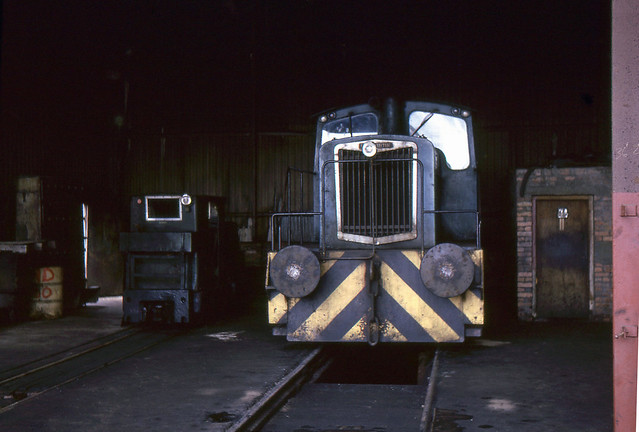 JUL 74 25. Standard and narrow gauge shunters at Cynheidre Colliery, July 12 1974 by Andy Kirkham, on Flickr
So the question was can I build a model of shed and including some std gauge shunting with some narrow gauge also in use... Thus I delved into the internet thing and found two 3 main resources...
1, Paul B's site which has 2 marvellous collections of pictures mostly of the rolling stock - https://paulbartlett.zenfolio.com/?q=Cynheidre
2, Old-Maps have a 1:2500 map from 1971 - see here: https://www.old-maps.co.uk/#/Map/249500/207500/12/100955
3, An photograph taken from above
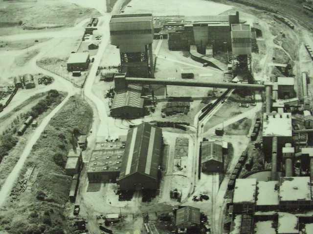 Cynheidre 9 by sapper537, on Flickr
So taking all this I've turned the map round to match the orientation of the photograph and traced over the track layout on the map so clearly show it. The question is can anyone provide any more details of the traffics on either gauge - I'm not really interested in the main colliery screens and associated marshalling yard being way too large to contemplate at the moment. Its the loco shed and the larger building on the left (large and bottom left in the photograph) that I'm most interested in, I'm guessing it's some sort of workshop / store area where wagons of pits props etc could be stored and transhipped into the NG wagons. On Pauls site there's pictures of NG Tubs with all sorts of purposes - Pit Props, Methane, Explosives, Misc Bolsters and of course Coal.
If anyone could fill in some details that'd be great, I can't imagine a huge quantity of coal coming out by rail rather than conveyor in a large modern colliery (although 2 shafts have 3 or 4 lines vanish inside) but the narrow gauge certainly did move coal as well as other things to construct / maintain the mines as you can see rakes of coal wagons on the photo. Were all of things things loaded in the one shed? How were wagons sorted / marshalled / arranged as there's not really any fans of NG sidings (unless they're inside the mystery building??
What about the Std gauge shed, such a shed surely only provided a loco for the track work on left hand of the plan? But I see 4 different sidings on the left but know not of their purpose (1 far left, 1 into the dual gauge stores?, 1 into the Shed and 2 further up the map - 1 to the area marked "Tanks" and the one further up...
Hope all that makes sense and someone can answer my questions!
Many thanks - and now I'd best scarper as I've been putting off my real (as in I get paid for) work as this is far more interesting - sadly 'real' works needs done for tomorrow morning!
Ralf

-
Hi Folks,
Has anyone got / an index to the back issues of Railway Bylines - I know there's a year by year one on the Irwell Press website BUT a) it stops with Vol 21 a few years ago and b) you can only search 1 volume at a time and c) it'd be nice to have some tags eg "NCB", "Colliery", "Mountain Ash" - from a personal perspective!
Has anyone compiled / made / got any alternatives??
Thanks
Ralf
-
Ooooh loving the idea of this one. Just flicking through the Harrogate Gas Works books and suddenly thought that New Park would make a lovely layout and wondered who modelled what of the system and then appear here! Good luck with it!
Ralf
-
Looks good, with a bit more room - especially as the station is right on the edge of the town, and there's a ferry right in front of it.
I'm leaning more towards not bothering with the station anymore, and just having the branch junction with a few sidings:
Think I preferred the previous plan in terms that the industry was further from the line than the loco servicing. Although generally prefer it without the station...
-
To my way of thinking, Inglenooks should have at least the appearance of trains coming from and going to somewhere else. My suspension of disbelief filter will not allow the layout to be a completely self contained piece of railway as I cannot imaginate the scenario.
Thanks Johnster & Brian for the further thoughts. Yes totally I agree with Johnster that trains do need to vanish somewhere/how!
I've gone and errr stolen a layout plan from another forum user and here's where I am at the moment, basically there's 3 sidings (not inglenook lengths but will have markers to set limits if I decide to play by the rules, but I've also included a loco shed (who doesn't want an extra loco sat on display, and a run round loop to avoid propelling trains on or off the layout. Trains will shuffle off scene onto a cassette or something on the left. Current thinking is c5ft plus 2ft fiddle opportunity, but may decrease scenic section a smidge.
It's the 1970s and the somewhere somehow this corner of a vast NCB system has wagons to maintain and lots of them, operation will simply involve shunting trains and forming a train for departure. The wagon shops will be the mainstay of the services with the kick back siding serving some rail served piece of this NCB yard but we've as yet to invent an excuse for a small inconveniently placed siding - maybe I should scrap it, but would rather include it.
Excuse the rough photoshopping and the terrible Templotting, the whole lot will be coated in rough dirty coal dust with puddles a plenty stock will be many and various depending how the feeling takes us! Only intended for home use at the moment but not ruling out exhibiting.
Thanks
Ralf

-
1
-
-
I kept it all visible, in a length of 5'8".
Albeit, there is a little used, hidden, sector plate).
Hang on a minute Brian - you mean to tell me there’s not an off stage area on the left? I’d always assumed that that’s how trains / locos etc arrived and departed the scene... Looks like I need to go and
find the relevant BRMDRAT it was model Rail and now BRM - I'd best go and buy a copy of 233 on eBay and then study it further...Also astonished the sector plate is only ‘little used’ - in my head it’s allowed locos to run round the train upon arrival to commence shunting the train, and allowed you to shunt into the kick back siding...
Much more thinking required....
Ralf
-
Hi folks,
Pondering on a Inglenook-ish shunting plank layout and have a question... It's probably a daft question but here it is.
Assuming I've got a total of 6ft in length available to me would you:
a) - include the shunting head shunt / exit line on the scenic section as per an official Inglenook
or
b) - have the first set of points just inside the scenic section? Giving longer sidings / more room for design BUT some sidings would only be accessible by taking the entire train into the fiddle yard / traverser / sector plate albeit briefly...
Any thoughts appreciated! I'm torn between the realism of being able to shunt on scene and the ability to maximise potential layout design opportunities by not letting some of the shunting happen on scene...
Ta
Ralf
-
Someone will prove me wrong, but I don't recall any colliery with "clean concrete" diesel facilities. In some cases the clean concrete came after the end of internal rail working.
{SNIP}
The landsale yard was common to many pits. Often located by the front gate, this lends it self to a backscene colliery. Many used hopper wagons discharging from a raised line directly into lorries. A weigh bridge could be an associated feature.
Thanks Dolium, I don't remember seeing any pictures but I'd have thought someone would have installed a new diesel facility for the new order of rail traffic... - Maybe not! I shall have to big round the Industrial Loco Shed volumes from the IRS and see what I find!
Thanks for weigh bridge and Landsale Yard thoughts, guessing that'd usually be a separate weigh bridge from the usual wagon weighing one for any outgoing wagon traffic?
What about the other end of the line, with the Inglenook representing the approach to a staithe (north-east), quayside (Whitehaven) or end tipper (South Wales)? The actual unloading facility might be a bit ambitious but that could be assumed to be offstage.
Thanks Pat, you mean allow the train to vanish behind something as if it's gone to the staithe?
You only need a single road shed, concrete slab and metal frame with wrinkly tin sheet. They were very common.
An old boiler as water tank.
I’ve done the same on Kirkmellington to match research I’ve done. Plenty of books available on industrial Railways & specific to their sheds too. Many also found on Flickr as per my earlier post if your can’t afford the books.
Thanks B&D Boy, but I'm trying to model probably a corner of a large complex so would need an excuse for a shed which wasn't the main one... I don't have any forthcoming but I'm sure one could be contrived?
Thanks all please keep the thoughts coming!
Ralf
-
Not many buildings to 'hem in' your railway, but plenty of operational inspiration.
Thanks for that Brian, I think I just about follow the method of working, trouble is my space is limited so single ended layout would be FAR preferable... Suspect I'm going to go down the colliery wagon works route - and just may have to shoe horn in a 'modern' diesel shed as a kickback couple of sidings that they've shoe horned into the site to let the new technology prove itself!
Have looked at the pile of locos I'd got lined up for this project and it runs to about 15 (2 Hattons, 2 DJ J94s, 2 Janus's, BR/Industrial 03, 05, 06, 08, 14, 17, Webb coal tank and some other bits which have slipped from my mind! So a grimey dirty wet colliery with a 'clean' concrete 2 road diesel shed appeals but of course that's space. I'm trying my best to dabble with Templot on my Mac and have gone to join the club as I've many issues struggling to get going with Templot. May resort to some Peco templates and plan things out in real life then hopefully improve and refine in Templot before actually doing any building.
Cheers
Ralf
-
Looking forward to it - my wallet isn't though! Especially not with Contikits being there again! - Although Phil & Bill sounds good too!
Ralf
-
For a South Wales prototype, have a look at the shed/wagon repair facilities at Big Arch, Talywaun; a very good exhibition layout of this already exists.
Thanks for the tip off - need to investigate that one......
Does it have to be a coal mine per se ?
.
Have you considered any of the following
e.g.
NCB Landsale Yard,
NCB / BR Exchange Sidings,
NCB Area Central Workshop
Thanks Brian no doesn't have to actually be a mine at all. Thanks for the suggestions I'll have a good Google of them soon, for once I'm trying to find pictures of industrial settings that don't have locos in the foreground! They just do get in the way of the scene don't they lol!
Thanks
Ralf
-
Hi Ralf,
If you are up to a bit of assembly, the SMP 3' radius plastic based kits could be an option. As explained in Nestor's other thread, French modellers have used SMP to represent Midi Bullhead carving the thin sleepers to give a more rustic appearance.
I was going to use Peco long radius. As it's an overall impression I'm going for, I decided these would be a fine option.
Thank you both, looking for shorter than short radius for industrial use so beginning to think C&L assembly is the way forward although this re-entry into modelling for me is supposed to be fairly simple but must admit pondering on DIY points - and while I'm there I could go EM then it all turns into a beginners snowballing nightmare!!
Thanks
Ralf
-
The points are the long version as they are all I could find, but also they add to the realism that I’m trying for. Although only 4 foot long with longer points has reduced the available track space but looks much more lifelike than cramming every little bit of wood with track. So all in I can just about squeeze 5 class 50s into the shed and sidings and another on the road from under the bridge.
Ah ok, thanks for letting me know. Certainly looks good so far, like the idea of DCC clag too!
Ralf
-
I would model a small corner of a larger NCB perhaps where there is or was a shed for repairing wagons
Thanks Dave, I think I'm going to do exactly that... Walkden Yard seems to meet my needs for a Wagon Repair shop, see Flickr links. Think I'd best get the Amberley Book "Walkden Yard" ordered....
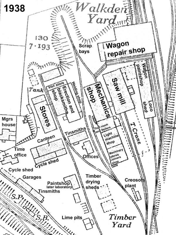 Walkden Yard, Lancashire, mining workshops 1936 by Pitheadgear, on Flickr
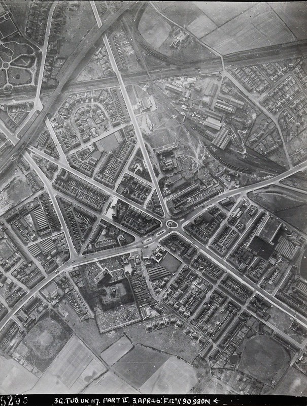 Walkden, 90 Sqdn RAF photo, 3 April 1946 by Pitheadgear, on Flickr
Thanks
Ralf
-
2
-
-
Nestor,
possible using the new Peco Bullhead track (I know it's not strictly correct for HO but once scenic-ed I think it'll look fine!).
What are you planning on using for your turnouts? Guessing not Peco Long Radius? Currently trying to work something vaguely similar out for my plans which will involve Bullhead rail.
Thanks
Ralf
-
Hi Mark,
Having started with an off cut of wood I tried some of the new Peco bullhead track
Impressive start from a off-cut of wood, way beyond my skills for sure woodwork-wise. Which points did you opt for to go with the Peco Bullhead? Guessing not the long radius Peco ones as your space is limited?
Thanks
Ralf -
Hi Folks,
Looking to kick start a revival of my modelling by building a simple yet entertaining NCB Style / Themed Inglenook layout to make use of my Austerities and Janus's I seem to have acquired fairly recently. Looking for some prototypical excuses / scenarios to kinda justify shuffling coal wagons with industrial locos...
Any thought, pointers, etc etc much appreciated. Whilst I say it'll be a straight Inglenook I am tempted with a run round facility and perhaps a kick back loco servicing road! BUT I do want this to be simple and cheap mainly as a project to learn and practise skills on. Also space is a premium likely it'll be 3ft x 1ft or 4ft x 1ft Tim Horn baseboard plus shunting stick on the end. BUT for now mainly looking for excuses and inspiration to justify a NCB Inglenook, I shall worry about the exact plan later on!
Bring it on...
Ralf
-
1
-
-
As you already have the tiebar hole, it should be easy to fit the analog motors from the underside (if there's enough room around framework)
Thanks for the input folks, a couple of points arise from the above:
Firstly - yes there's a hole in the tie bar but NOT in the baseboard (the wire in tube is hidden in the scenery / underlay / ballasting), so I'll need to drill from above to precisely locate where I need to enlarge the hole from below... Bit nerve-wracking but I'm sure it's possible...
Secondly, I had considered Tortoise motors but didn't think slow action motors were suited to working with sprung bladed points?
Many thanks
Ralf
-
Hi Folks,
Looking for some inspiration in solving a dilemma, my layout (purchased second hand) has Peco code 100 points operated via a Wire in Tube method to the back of the layout. Fine that's all ok BUT I'd like to operate it from the front...
I've tried running wire in tube in a U shaped method back to the front of the baseboard and whilst it works the resistance is such the points don't change very solidly and it's all a bit spongy esp the electrical connection for the blades - no there's no wires on all rails here...
So I cunningly decide that a solonoid on back oppating the Wire in Tube would solve the problem of not being able to reach and hopefully whack the blades across hard enough.
Initial trials (see photos) show this isn't working either as the solenoid doesn't travel / swing / move far enough to persuade the spring in the points to spring across, works fine in one direction but not the other.
So what are the remaining options? Thinking it's either a surface mounted solonoid on a bit of wood on the rear of the latout so there's no vertical wire, or drilling from below and installing a solonoid directly below the point which seems risky to put it mildly...
Any thoughts / hints / tips much appreciated.
Thanks
Ralf
ps there's a mixture of short and Y points should it matter...


1:2500 OS Maps - Printing them? Grid Size?
in Modelling Questions, Help and Tips
Posted
Thanks John & Rich, thanks for the info but I don’t think it answers what I’m trying to get at...
Because I’m printing a screen grab I don’t know how many mm square the grid boxes should be on my paper printout...
Cheers
Ralf