

Mike Boucher
-
Posts
888 -
Joined
-
Last visited
Content Type
Profiles
Forums
Blogs
Gallery
Events
Exhibition Layout Details
Store
Posts posted by Mike Boucher
-
-
Be interesting if taken to an exhibition, as everyone would have to stare at the layout...
I scrapped my approach to building an ironing board layout in 00 and bought traditional baseboards. It got too heavy quite quickly, so watch the weight of wood and other materials etc.
It would be worse if if it was the Silence, everyone would forget about the layout as soon as they looked away...
-
Reading and Northern 4-6-2 was running excursions today, and someone decided to try to leave a parking lot without Stopping, looking, or listening. No crossing gates, apparently, as it was a parking lot, but how the hell did they NOT hear the whistle and notice the big, blue locomotive coming at them.
No injuries, no major damage to the loco, but a few shaken up people in the car, and I'm sure the engine crew was a bit upset. Passengers were apparently unaware until they stopped.
Video on you-tube, reaction from a spectator makes in not exactly safe for work audio...
-
I'm bored at my desk and noticed an item that I always put out but never used, and finally found a use to it. My other hobby is Doctor Who and about 10 years ago made this 'shaker maker' TARDIS that just so happens to be O gauge, or just looks in proportion to the figure size. Its made out of something similar to poly filler, so there are minor scrapes and dents but nothing to worry about as its just a background item.
Here's the box from Google Images, the loco shows its atleast 10 years old.
Now all you need is a 1" tall weeping angel statue somewhere...

-
Finally a comparison shot showing the loco face to face with my Jinty. The DB loco towers above the Jinty even though it is built to the smaller scale of 1:45 compared to the Jinty's 1:43.5. Massive eh!.
Somewhere, I have a photo of my Dapol "Terrier" sitting next to my C&O Allegheny 2-6-6-6...


-
 6
6
-
-
Does anyone know the purpose of the dark green tower in the background of the first two of Night Train's pictures? Is it railway related?
Its a switchman's shanty, also known as a gatekeeper's shanty. The switchman/gatekeeper was responsible for manually lowering and raising the crossing gates when a train was approaching, and these shanty's would be elevated in cases where the he would need greater visibility down the tracks. (so he could see over other structures, parked freight cars, or the like)
I noticed it right away, neat little structure.
Here's another example, captured by the incomparable O Winston Link...
BTW - I remember manually operated gates in Lawrence, MA, back in the early 1970s. Waltham, MA, still had a gatekeeper into the 1990's, although the gates were automatic, the gatekeeper would still walk out onto Moody St with a red flag.
-
2
-
-
I think that putting wires on the poles is asking for trouble as they will get in the way when track cleaning. In any case the wires would have to be very thin or they would look unrealistic.
Rod
I tend to agree Rod, but EZ line (iirc its name correctly) is flexible and looks scale in 7mm........
Ramchester with the signals and TPs is almost transformed it was an excellent model before and now its superb...surprising (Im surprised) how these items are so 'railway like' and just how transformative they are.
I was merely interested to hear yours and Howard's thoughts on TP wires.
Kindest regards,
CME.
Hi Rod,
A friend uses EZ line (yes, CME, you have the name right) on his NTrak module. It looks fantastic, and it can handle the abuse that a portable NTrak module takes. its available as thin as .010" diameter. great stuff.
He got his from Berkshire Valley, and I think its available via amazon. Its also not too expensive, about $10 for 100 feet, you could do most of Ramchester for less than that Parkside brake van you're working on.
And, IMHO, With the rest of the detail you're putting on Ramchester, I think the lack of wires would look really obvious, their absence would be noticable. I think you should look into trying it.
-
-
And in between other things this evening I've completed adding the internal skin to the top half, plus cut holes in the end for the vents.
Floor planking units scribed, think I'll model the doors open as per most of the pictures I have of Bodmin North.
Hi Spams,
Looking at the photos, I was wondering why you had made a multi-thickness piece, then I realized it was a concrete building and you needed to model the thickness for the windows and the doors.
But... Why did you spend the time/effort to make the rear wall that same thickness, when there are no openings. Seems like you could have easily used a single thickness styrene sheet, and once the roof was on you would never notice.
-
Stretching the topic a bit... How about Golf Course Running? Boston and Maine Turners Falls branch, circa 1980. (branch abandoned 1981)

-
16
-
-
Well, I had some tests last week (CAT scan, bone marrow biopsy) and the results show i'm in "partial remission". Which means that, while the cells are still floating around in the bloodstream, there aren't as many, and my lymph nodes are shrinking. That means the treatment is working and the disease is trending towards total remission.
What it also means is that I'm done with infusions, which mean no more treatment room modelling (for now). I still have a daily pill to take, and appointments every few months, but until they stop seeing progress and things start heading the wrong direction, this thread will go into hibernation again.
Thanx for all the encouragement, and for following along.Now I need to find time at home to finish these projects (and my other ones). You can follow along on my "regular" workbench thread where at last updating, I was doing battle with a Connoisseur "Jinty" that I had made a hogs breakfast out of...
http://www.rmweb.co.uk/community/index.php?/topic/18405-bouchs-workbench-7mm-jinty/page-6 ,-
7
-
-
Hi Phil. Oh there is a battle in Washington right enough. Sadly we could not get in the White House as Trump has blocked foreign visitors, even though our son-in-law in a Captain in the military police doing a 12 month term in the Pentagon.
However our daughter is ex military and is able to get us on military bases to use their accommodations.
if you had a Russian passport, you probably could have gotten in...
-
That's a wonderful model. That kit is on my "wish list", I can only hope I do 1/2 as well.
-
Not being a fan of 'Nanny' but surely this bloke is an idiot who seems to have totally ignored sensible advice from those that know. https://ehs.research.uiowa.edu/liquid-nitrogen-handling
Yeah, I noticed he was playing with liquid nitrogen without gloves. Guy must be a few french fries short of a happy meal. (apologize if this is a "americanism") I suspect most you tube videos don't demonstrate what you would call "safe behavior"... He probably has this shirt in his closet

-
... especially as my German is very limited - what a challenge.
I couldn't read Rod's message without immediately thinking of this:
-
How does one grate the chinchilla? Don't they complain?
Dip them in liquid nitrogen first, makes it much easier to grate. Or at least they shatter into small pieces when you hit them with a sledge.
-
1
-
-
For yesterday's progress, I'll simply let the photos do most of the the talking...


It you look closely, you'll see a little sliver of brass on the main crankpin, that's the side I needed to fix. She rolls without any binding, so I'm going to declare my fix a success.
There might be too much pressure from the pickups, since it doesn't roll well, might need some tweaking there. We'll see how well it goes once the engine is in.
I didn't work on anything else, since getting the wheels/running gear on took up the entire treatment.
-
5
-
-
As I noted in my last posting, I had a broken crankpin on the Porter drivers. Here's what I did to fix it...
First, I needed a new crankpin. Measuring the undamaged crankpin showed it to be .062" diameter, with a .040" hole about .125" deep. I didn't have any .062 brass rod, so I had to turn it down from .125... Since such a small diameter tends to flex, I spotted the end with a centerdrill to use a center for support. Then, with the lathe at its highest speed, turn to dimension...

After to size, I drilled the hole in the center. Again, highest speed, a "brass drill", gentle feed, and a lot of cutting fluid.

Next was to drill a hole in the driver exactly where the broken crankpin is. I made a simple jig for this. Took some styrene and drilled a .062" hole in it. Then I placed that over the remains of the crankpin, and glued a thin strip of styrene against the tread, kinda like a cradle for the driver.

Since there was a little stub of the crankpin still there, and a slight "prickpunch" from there the .040" hole ended, I could make a .040 pilot hole, and then clean up the remains of the original crankpin and then drill out to the .062 final dimension. So, I took a smaller scrap of styrene and drilled a .040" hole in it. I put the drill in the new, brass crankpin, put the crankpin in the jig, and then put the styrene over the drill and glued it in place.

This would assure that I could drill a pilot hole exactly centered on the crankpin. Here's what it would look like "in use", with the stub of the crankpin in the hole...

Next I needed to drill the hole exactly square with the driver. I took a piece of scrap brass that had a small hole in it (a botched piece from a model engineering project I built a few years ago). The hole was larger than the axle/axlebox, but smaller than the driver diameter. I cut out a slot to the hole. Then put it on parallels in the drill press vice.

With the driver in place, its obvious how/why this works...

Then I put the plastic jig over the driver, lined everything up, and drilled through .040"

Then I opened up to .062" diameter. I cut the brass crankpin to length, it was a tight sliding fit, could push it in and it would stay, but didn't take much force to pull it out. I used 1/2 a drop of 5 minute epoxy in the hole and put new the crankpin in.
And here we are, ready to build the running gear.

Fingers crossed that it doesn't bind when I put the rods on...
-
2
-
-
Jason, thanks for that link regarding the KMT models and consequent use by RMT, all new to me, and definitely what the caboose is. I suppose over the pond this sort of thing is readily available for peanuts. The postal charges from the states seem to have gone mad in the last few months. Anyhow, I had an RMT meet this afternoon
To be completely honest, I've been a "2 rail O scale" modeler on "this side of the pond" for 20+ years. Can say I've ever seen either that caboose or the "beep" for sale at any model RR show I've been to. They're not very common over here, IMHO.
Now, if you ask about the Atlas diesel switcher you've used as a donor for your beep's power, yeah, they're pretty common. Saw one at a show just a few weeks ago for $25, and I decided I didn't need it, even at that price...
BTW - nice find on that caboose. The body looks reasonably well detailed and well proportioned, and those end railings are easily sorted out. Definitely would have paid a 5 for that...
-
Today was perhaps a good day in so much as the visit to the urology department at the hospital went reasonably well for my wife. For the past 9 years she has been regularly monitored after her cancer surgery and today we thought she would get the all clear. Sadly she was informed that it will be at least 2019/20 before she will get the all clear. Somewhat puts modelling well down on my list of priorities.
Best wishes to your wife.
-
Hi folks,
This months trip to the treament room was a mixed bag. No work on the Porter due to a disaster, decent amount of work on the Midland Brake, and an short update on the Arizona.
First, I had planned on getting work done on the porter, as the next step in the instructions is to get the running gear done. I had hoped to have at least the side rods on, so I could push the loco across the table, but immediately ran into an issue. Since a picture is worth 1000 words...

No clue how/when this happened. The driver centers are "slippery, engineering plastic". Solvents dont work on them, and ACC doesn't have great shear strength, and that's the type of force that would be acting on a crankpin. And there's not a lot of contact surface there to begin with. Since the drivers aren't available from Grandt anymore, this leaves me basically two choices.
1) Glue it together with 5 minute epoxy and cross my fingers
2) Drill a hole where the existing crankpin is, and build a new crankpin out of brass, either a push fit into the hole, or use ACC to secure it. and cross my fingers
Strongly leaning towards #2. Seeing as I have three lathes, ranging between a Boley watchmakers lathe up to a 10" South Bend. Obviously this fix has to be done at home...
So, I worked on the Midland brake. Between the last treatment and this one, I did a few things at home.
1) Added weight (work with lead at home!)

2) Painted the roof pieces black
3) Painted the etched brass window bars white.
4) Painted the duckets and the "whatever the hell that marker-lamp-looking thing above the duckets is" crimson. Since they were molded a darker color than the sides, the crimson came out darker.
At treatment, I glued the duckets and the "whatever that thing is" to the sides. The duckets had a nice molding on the "wall side" that fit directly over the ribs on the sides, so they locate in position quite nicely.
Since the windows need to go in before the roof goes on, that was first. Used ACC to glue the bars to the clear styrene, cut around the perimeter of the brass etching, and then Microscale Krystal Klear to attach them to the side of the van.
I drilled holes in the roof for the gas lamps, and glued them in place from the inside. They're not painted yet, as I'm not sure what color they should really by. the box shows them as a "steel gray" color, I don't have any other photos, and theres no guidance in the instructions. Any suggestions? I made my small pilot hole in the wrong position intially, but I easily filled that with styrene rod, just needs some touchup paint.
The instructions to attach the lower roof and the clerestory sides was worded strangely, but I figured out what they meant. They say to glue the clerestory sides in with the lower roof, and then after, pad the internal dividers with 1.5mm strip to fill the expected gap. I found it all but impossible to have the clerestory sides stay in position, so I glued the 1.5mm strip in first, then held the lower roof and clerestory in position and glued the clerestory sides to the strips first, then the center of the clerestory sides to the lower roof, and then the center of the lower roof to the top of the main body sides. Then I worked my way out from the center gluing everything else.
The instructions say to wait 24 hours before gluing the center roof on, so that's where I stopped. Here's a photo with the center roof held on by gravity...

This left me about 30 minutes left, so I did more work on the USS Arizona. I've done 10-15 minutes on this just about every treatment, but haven't really taken photos of it. But now, its starting to look regognizable.

Note that the superstructure isn't permanently in place, which is why there's a gap between it and the deck.
And after taking the photo, I realized that the turret at the bow (right of the photo) is in the wrong position, it had to be moved back closer to the superstructure. That's been done.
Next update will hopefully be a report on fixing the Porter wheels. Until next time...
-
4
-
-
Last night saw more small steps - quite literally in that I made up the rather nifty etched steps for the Tevan
 Then I did a bit more on the V4 brake van getting the floor cut and fitted ready for soldering in once I have fitted the brake gear etc. - I made the floor from a scrap etched part and I have yet to decide whether to fill the holes with rod or leave them. - There are only 5 and they are less than a mm in diameter and will they be seen with the roof on, I doubt it.
8>< snip ><8
I built a Parkside "Mica". Those little steps were the first pieces I ever made in etched brass. Wonderful little pieces of brass origami.
As for the holes in the floor, I wouldn't bother, you'll never see them once its done, painted, and on the layout.
-
Thanks Peter, yes, and it took a long time! I needed to build a jig, similar to the one that Ian Rathbone uses, and describes in his book. I couldn't have done the splashers without it. The boiler bands were from Fox.
Regards
Sandy
Can you post a photo of said painting jig? Thanx!
-
I'm told that proof readers read backwards, as it diminishes the tendency to see what you expect to see.
Of course, I don't actually know any professional proof readers, so this is heresy or was that hearsay...
Best
Simon
At a company I used to work at, the technical documentation writer would always turn the draft upside down and read the text backwards as well. She said it forced her to concentrate to read every word.
-
2
-
-
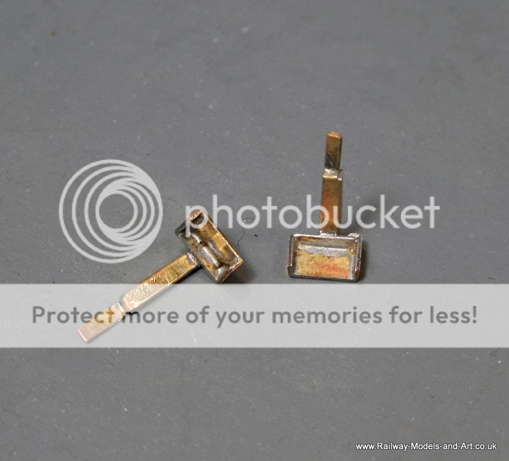
Yes I did enjoy it Andy, always helps when a kit falls together.
Wondering if I could add some working sidelights but am thinking where to put a battery!
Hi Brian,
Get one of these and attach the battery holder up on the underside of the roof...


Minerva GWR Pannier Tank - open for advanced orders
in Minerva
Posted
Hi folks,
Quick questions:
What's its scale top speed?
Has anyone tested its pulling capacity? (i.e. - X wagons or Y coaches on flat track)
How much does the loco weigh?
(BTW - I've ordered a 57xx, but I'm just wondering...)