


Entry posted by Knuckles
862 views
Note to readers: Please can you advice on the pictures? All my pictures seem to have the additions removed and so unless you copy and type them into your browser you can't see them. I haven't changed anything but RMweb clearely have. If I can't sort it easily then it seems people wil get bored with no pictures and I'll have a massive job trying to sort the pictures out - probably not bother. Please advice????

Stress & Success
Minues the Dingham auto couplers with electronic magnets that I wish to try, and some ideas on yard / building Lamps; the layout is fully wired and working! Not without a battle though.
As I have stated before, I read several books on model railway electronics and nothing would stick in, conversations with people and diagram studying were mostly fruitless and it's been like that for several years. I was however determined to wire my own layout so things work and so I've persevered. The instructions that came with the Tortoise point motors resulted in much confusion becasue I didn't understand any of it, and if I'm honest still don't - they seem to be written for people with at least 5 brain cells, I however only have 3 when electrics are concirned, and so after I was looking at the S4 page on Tortoise wiring I again rolled into a ball and spent a whole hour and a half arguing with my parents as to the interpretation thereof. It doesn't help when the diagram colours of the DPDT switches are the same as on the Tortoise becaue I couldn't decide weather that meant they had to be joined or weather it meant two seperate power supplies; again, obvious for many, but for electronic Dumbo's like me, an enigma. Thankfully, after crying for help, RobM came to the rescue with a fully brocken down, dummy proof explanation that was to be read in conjunction with the S4 sheet. After studying this it all clicked into place and I subsequently wired the whole layout by myself without again refering to the sheet or any other wiring information.....odd. RobM - Thankyou very much! Maybie your explanation should go in the S4 Digest in conjunction with the diagram.
Also I said this before breifly, but to whoever is responsible, thankyou for publishing me and a few others efforts in S4News 180, I was supprised but very happy to see that, but who to thank?
So anyway, electrics aside, once I had some understanding it wasn't exactly hard, just a case of repeating the same circuits again and again. One thing I will say that I found a tad alarming is the amount of wiring needed for such a small layout, and I wired this with DCC in mind too so no section switches (Operating with 2 DC controllers at the mo, one for points, other for loco).
Initial testing was, 'interesting', 3 out of the 4 switches worked, and after a mini inspection I noticed that I had wired one wire into the wrong terminal block, so that was easily fixed. I had to swap a few switch polarites around for panel preference, but that was easy enough, just swap a few wires around, and I had to do the same for the frog polarites. I struggled with the single slip polarity though so after asking for help Keith kindly responded with the life saver. Just that teeny bit of information helped a great deal and only 2 wires needed swapping to cure it. Namely, "Set the single slip to the slip/curved road first, get those polarities sorted and everything else should fall into place", or words to that effect. Awesome. 
Building the control panel:
This turned out to be a bit of an abortion effort, I buggered the wood work up and so nothing really fit properly. I bodged it with tacks and glue.  I made a pigs ear of the hole I was cutting for it too as the Jigsaw veered to the side and made a mess. Future lesson; don't bother cutting holes out that need to be perfect with one of these, maybe a Coping saw or Junior Hacksaw or something would be better as you have more control. I also found out that the DPDT switches I brought didn't fit on the panel becasue the 6mm Ply' was made from three 2mm layers, so I had to...erm...strip a layer off. :? Lots of old fashioned hand graft for an hour or so. SOooooo anyway, I added a thin bit of plastic card to the front and marked the track plan out with insulation tabpe, I didn't have the lining strip thus the uneven thicknesses, but it looks ok for what I'm doing. And one more word that describes my exquisite level of sophistication, the mounting 'bracket' is Bluetack! (This will be replaced with swing locks or something)
I will be adding plugs & jacks to connect the controllers but for testing I'm using the screw terminals...Glued on! I did use a stapel from my gun but seeing as it went right through to the otherside marming the presentation I decided to put that idea in the bin.
Piccies:
Well that was blooming lucky, they only just fit together.
http://i86.photobucket.com/albums/k112/sparkshot/1pan.jpg"]http://i86.photobucket.com/albums/k112/sparkshot/1pan.jpg
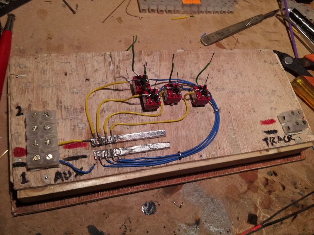
An enjoyable couple of hours work, all my own design. Works fine as it's essentially daisy chaining but with out the chain, because the feeds and returns are all on their own pads I think 'Lilly Padding' makes more sence. I didn't have the self adhesive copper strip so I used PCB strip cut to size and secured with...you guessed it...bl...no not Blutack, the other one. Super Glue. Full of pinache me.
http://i86.photobucket.com/albums/k112/sparkshot/2pan.jpg"]http://i86.photobucket.com/albums/k112/sparkshot/2pan.jpg
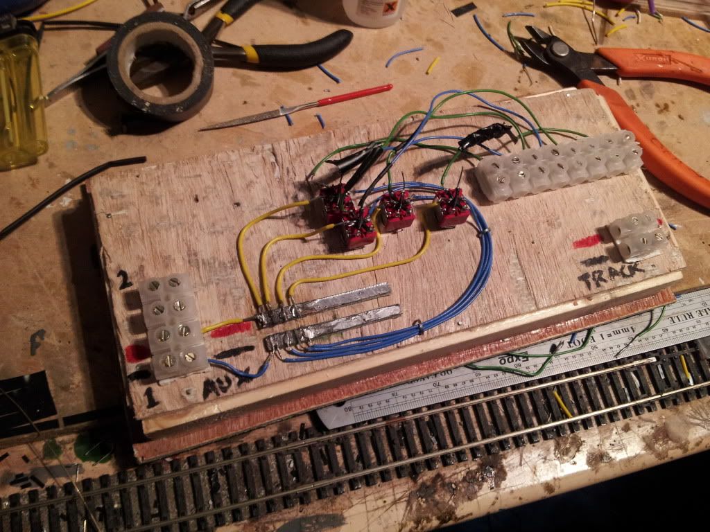
Basically done, just a couple more needed.
http://i86.photobucket.com/albums/k112/sparkshot/3pan.jpg"]http://i86.photobucket.com/albums/k112/sparkshot/3pan.jpg
And temporaraly rigged to the layout with two DCC controllers that represent the two outputs that the DCC system will have. One 12VDC and the other a bit more or whatever..
http://i86.photobucket.com/albums/k112/sparkshot/4pan.jpg"]http://i86.photobucket.com/albums/k112/sparkshot/4pan.jpg
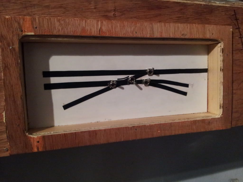
This is what the front looks like...
http://i86.photobucket.com/albums/k112/sparkshot/6pan.jpg"]http://i86.photobucket.com/albums/k112/sparkshot/6pan.jpg
This is Godzillah causing havok
http://i86.photobucket.com/albums/k112/sparkshot/5pan.jpg"]http://i86.photobucket.com/albums/k112/sparkshot/5pan.jpg
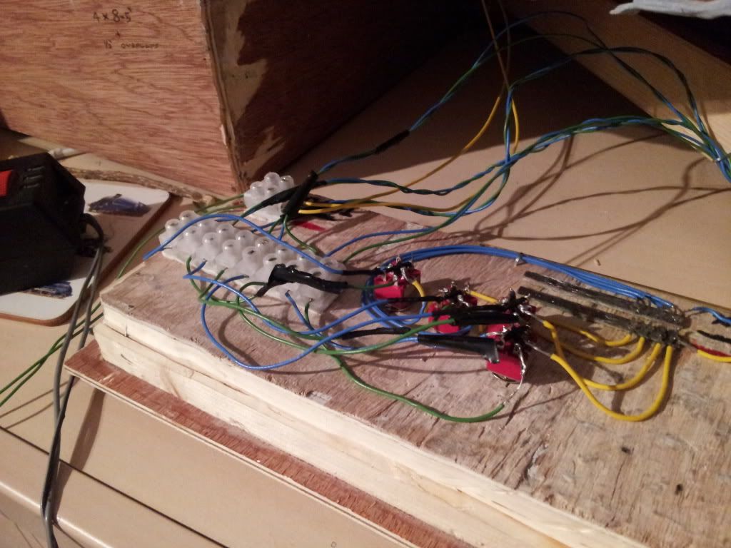
And this is my highly asthetic artwork, influenced by spagetti, a mine of serpents and that box of 1980's electronic bits of bobs you found in the loft all tangled together, but it works! Some wires are bare with only 5mm or so inbetween but due to the sprung pressure I'm not worrying about that at the moment.
http://i86.photobucket.com/albums/k112/sparkshot/7wire.jpg"]http://i86.photobucket.com/albums/k112/sparkshot/7wire.jpg
http://i86.photobucket.com/albums/k112/sparkshot/8wire.jpg"]http://i86.photobucket.com/albums/k112/sparkshot/8wire.jpg
One turnout wasn't throwing properly anymore, and so I spent over 5 hours last night getting wound up over it, had to take the whole thing out, fabricate about 3 different TOU's and endured much piddeling about. Eventually I threw asthetics in the bin and decided to just have a horrid old PCB sleeper/stretcher bar do the job instead. This was a bit stiff so I drilled two holes in and simulated Normon Solomon's method without Lace Pins - brass wire bent into a sort of square 'C' chape with one end extended, the long end solders to the rail web, the other is underneither the stretcher and as it's bent gives a locking pin effect. Again, more extreem sophistication that would put the 'EM' creators of 'Liverpool Lime Street Station' to shame!
I thought it was throwing ok until nothing worked, so I got my tester out and yeeees, I shorted the entire layout out...sooooo, I wasted almost 5 hours.
Bedtime.
Morning.
Ok, today I spent about half an hour tweaking again, and this time for some reason it is ironically the best throwing turnout I have now, albeit the ugliest.
http://i86.photobucket.com/albums/k112/sparkshot/9bar.jpg"]http://i86.photobucket.com/albums/k112/sparkshot/9bar.jpg
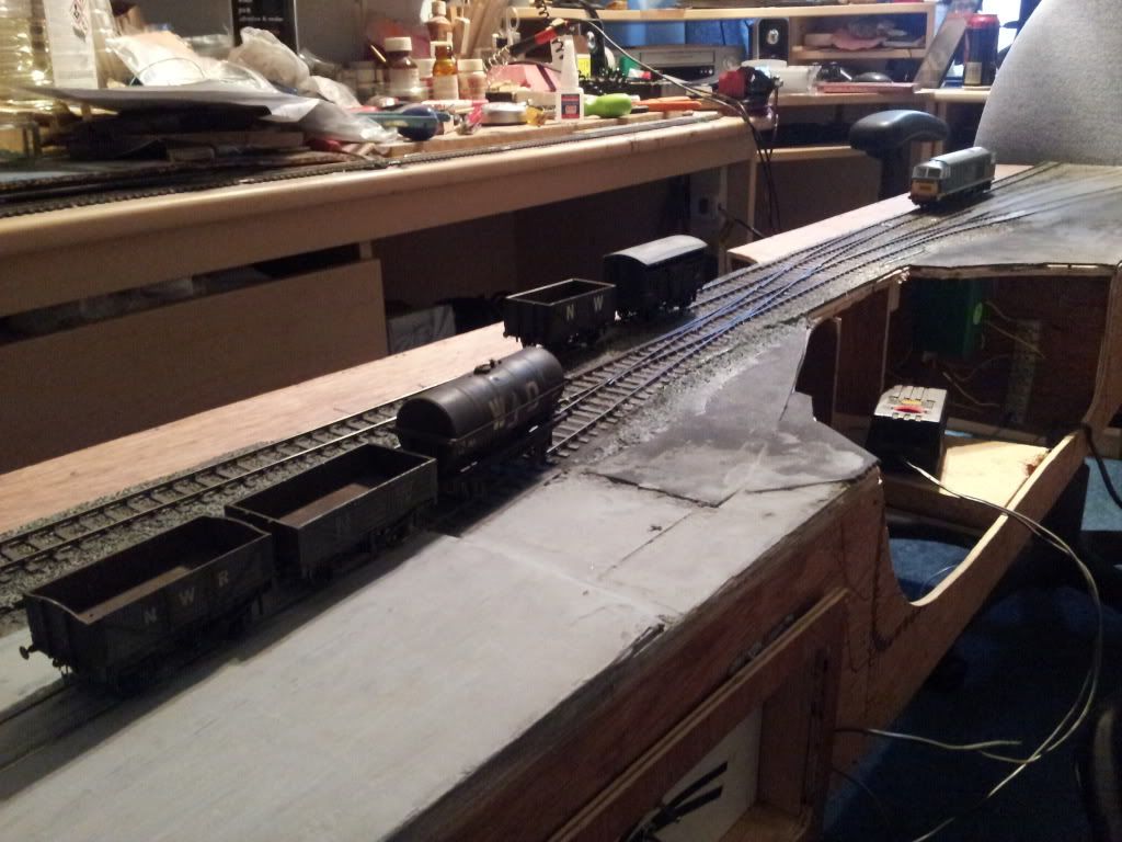
This is just a shot that gives an impression after I was playing testing.
http://i86.photobucket.com/albums/k112/sparkshot/10impression.jpg"]http://i86.photobucket.com/albums/k112/sparkshot/10impression.jpg
Unsure what to say to close this post so I hope you got something out of it, enjoyed it even. I'm happy that apart from couplings I have to some degree a working layout and so it 'might' be safe to recommence some scenic work...or build an engine, or sort the couplings, or...?
I feel I've achieved a lot despite it's humble appearence. I'm happy and supprised I've got this far. Not only have I done this all myself, but electrically it works, I flick a switch and a point changes and that to me is something I've never had the pleasure of save for a few sessions at th emodel railway club. My previous 2 (3 or 4 sortof) layouts didn't work like this does, and to top it off, all in P4.
-
 2
2

6 Comments
Recommended Comments
Create an account or sign in to comment
You need to be a member in order to leave a comment
Create an account
Sign up for a new account in our community. It's easy!
Register a new accountSign in
Already have an account? Sign in here.
Sign In Now